EverHot BL1 Series User manual


A company that proposes sunny solutions, working with
passion and devotion, for three decades now, to always offer
the best.
A philosophy that leads our steps, and makes us, as
professionals, feel the weight of responsibility and obligation
to offer products and services that are in harmony with the
environment and man. So that we hand over a better world to
our children.
We live in times with great ecological problems. Planet
Earth is sounding the alarm of ecological danger. The
thoughtless use of mineral energy sources is resulting in
increased pollution of the atmosphere, above tolerance
levels.
Ecosystems are either being transformed or destroyed. While
mineral energy reserves are continuously decreasing and
prices continuously rising, we look at the sun and consider that
it radiates over 15.000 times the energy needs of our planet.
So why not direct ourselves to the inexhaustible, free, and
above all clean solar energy?
2

Solar System
•Why should we use a solar system. . . . . . . . . . . . . . . . . . . . . . . . . . . . . Page 4
•Packaging . . . . . . . . . . . . . . . . . . . . . . . . . . . . . . . . . . . . . . . . . . . . . . . . Page 5
Hot water consumption / use
•Calculation of needs / Examples . . . . . . . . . . . . . . . . . . . . . . . . . . . . . . . Page 6
•Forced circulation kit –Function . . . . . . . . . . . . . . . . . . . . . . . . . . . . . . . Page 8
What a solar system consists of:
(technical characteristics,
specifications)
•Solar collectors . . . . . . . . . . . . . . . . . . . . . . . . . . . . . . . . . . . . . . . . . . . . Page 9
•Boiler EVERHOT type BL1, with one tube heat exchanger . . . . . . . . . . Page 16
•Boiler EVERHOT type BL2, with two tube heat exchangers . . . . . . . . . Page 16
•Hydraulic kit . . . . . . . . . . . . . . . . . . . . . . . . . . . . . . . . . . . . . . . . . . . . . . . Page 19
•Differential Thermostat. . . . . . . . . . . . . . . . . . . . . . . . . . . . . . . . . . . . . . . Page 22
•Peripheral accessories - Basic Accessories . . . . . . . . . . . . . . . . . . . . . . Page 23
•Peripheral accessories - Optional Accessories. . . . . . . . . . . . . . . . . . . . Page 24
Solar Systems
•Forced circulation systems –Models. . . . . . . . . . . . . . . . . . . . . . . . . . . . Page 25
•Typical installation diagrams . . . . . . . . . . . . . . . . . . . . . . . . . . . . . . . . . . Page 26
Installation Instructions
•Installation Instructions . . . . . . . . . . . . . . . . . . . . . . . . . . . . . . . . . . . . . . Page 27
•Support base of collectors –installation instructions. . . . . . . . . . . . . . . . Page 28
•Connection of collectors and accessories . . . . . . . . . . . . . . . . . . . . . . . . Page 36
•Hydraulic kit and piping . . . . . . . . . . . . . . . . . . . . . . . . . . . . . . . . . . . . . . Page 38
•Electric connections. . . . . . . . . . . . . . . . . . . . . . . . . . . . . . . . . . . . . . . . . Page 40
•Lightning protection . . . . . . . . . . . . . . . . . . . . . . . . . . . . . . . . . . . . . . . . . Page 40
•Overheating . . . . . . . . . . . . . . . . . . . . . . . . . . . . . . . . . . . . . . . . . . . . . . . Page 40
•Snow and Wind loads . . . . . . . . . . . . . . . . . . . . . . . . . . . . . . . . . . . . . . . Page 40
•Inspection Checklist. . . . . . . . . . . . . . . . . . . . . . . . . . . . . . . . . . . . . . . . . Page 42
•Instructions to the end user and Installer. . . . . . . . . . . . . . . . . . . . . . . . . Page 43
•Installation sheet . . . . . . . . . . . . . . . . . . . . . . . . . . . . . . . . . . . . . . . . . . . Page 44
•Instructions for the Installer . . . . . . . . . . . . . . . . . . . . . . . . . . . . . . . . . . . Page 45
3

2
WhyshouldweuseaSolarSystem
a solar system Is Ecologically friendly. Economical, Simple,
aesthetic, Effective and autonomous:
•Ecologically friendly:
With a Everhot 500E system, the emissions of C0 Avoided
Annually are equivalent to the fuel emissions of a car having
run for 10.000 km.
•Economical:
will decrease your cost for energy by 70 -100% because the
burner and electric resistance will not need to operate for at
least 7-12 months of the year, depends on the sun radiation of
each area and the size of the system.
•Simple:
The well-studied selection of materials of Everhot make Its
Installation safe and easy, reducing the time needed for Its
Installation to a minimum.
•Aesthetic:
The excellent exterior design of the Everhot collectors in
combination with their well-studied support base, offer the
possibility of a tangent Installation on tiled roofs matching
aesthetically with every architectural building design.
•Effective and Autonomous:
You have hot water at will 7-12 months per year. During winter
time you secure the pre-heating of the water, and the extra hot
water needed is secured from conventional energy.
4

The forced circulation system EVERHOT consists of
Thank you for choosing to buy a solar system EVERHOT Bl1 or Bl2.
Every system which you acquire consists of:
1. Boiler with one tube heat exchanger (type BL1) or with two tube heat
exchangers (type BL2) on a wooden palette and wrapped with stretch film.
2. One (1), Two (2), or Three (3) collectors which are protected during their
Transport with 4 plastic elbows of hard plastic.
3. Cardboard box with all of the accessories (except pipes and wires) which are
required for the installation of the system like hydraulic kit, expansion vessel,
differential thermostat with plastic case, antifreeze liquid and various
connection accessories in individual plastic packaging. Externally the box
refers to the model of the system for which the accessories are for.
4. Cardboard box with the metal plates of the support base, the screws, moly
plugs, the bolts etc…
5

General Information on needs of hot water
When choosing a solar system for hot water we must first determine our needs for hot
water, in quantity as well as in preferred temperature of consumption. The typical
calculation for the temperature for consumption is 45ºC, but for the calculation of required
quantity you must take into account the daily needs.
Calculation of needs for hot water usage
In family residences, the needs for hot water remain stable during the whole year. An
indication for the needs is given by the number of individuals living in the building (or
apartment). Usually, the per capita daily consumption of hot water at 45ºC is calculated
taking into consideration the following:
Low consumption: 35 liters per capita / day
Medium consumption: 60 liters per capita / day
High consumption: 80 liters per capita / day
In the case where we want to connect to the solar installation the washing machine and the
dishwasher, we would have to increase the calculated daily needs of consumption as
follows:
Washing Machine: 20 liters / day (1 wash per day)
Dishwasher:
20 liters / day (1 wash per day)
Example:
A family of 4 persons needs around 240 liters of hot water daily in order to have a medium
daily consumption. (60 liters per capita x 4 persons). If we include a washing machine and
dishwasher, then we must calculate a consumption of 280 liters per day.
In buildings such as hotels, hostels, etc…, the needs for hot water are related to the amount
of customers. In this case the daily consumption is calculated by the average occupancy
of the rooms, from the period of May up until August. Using this basis, the size of the pro-
posed installation is determined. Here below we indicate the per capita daily need for hot
water at 45ºC
Hostels with rooms with shared bath: 35 liters / person / day
Hostels: 40 liters / person / day
2 Star Hotels: 50 liters / person / day
3 Star Hotels: 80 liters / person / day
4 Star Hotels: 100 liters / person / day
Camping: 60 liters / person / day
6
2)HOTELS-HOSTELS
1) RESIDENCES
General Information

General Information on needs of hot water
Example:
An installation of agro tourism is maintained by a family of 4 persons that live in the
residence. During the period between May and August the average occupancy is 15
clients per day. For the occupants 2 meals are prepared per day and the dishwasher
washes 5 times per day.
Needs of family: 4 x 60 lt = 240 litres / day
Needs of the clients: 15 x 50 lt = 750 litres / day
Kitchen: 30 x 10 lt = 300 litres / day
Dishwasher:
5 x 20 lt = 100 litres / day
Total: 1.390 litres / day
In the next table we present the daily consumption for other applications:
Hospitals and clinics: 80 litres / bed
University residences: 80 litres / bed
Dressing rooms, public showers: 20 litres / person
Schools: 5 litres / student
Restaurants: 8 to 15 litres / meal
Bars: 2 litres / client
Prisons: 30 litres / person
Factories: 20 litres / persona
Offices: 5 litres / employee
Gymnasiums: 30 litres / user
The information of the above table can also be used in combinations so that in every case
the average daily consumption can be properly calculated.
In the case that a recirculation system exists for the hot water usage, you will also have
to take this into account for the needs. The calculation will have to be made every time
individually from the above tables and depends on the dimensions of the circuit and it’s
thermal insulation. Additionally, in the determination of the total needs, the thermal losses
of the total distribution circuit from the point of storage to the points of final consumption
must be taken into consideration.
In every case, the real needs for hot water are related to the personal attitude, the possible
special characteristics and habits of every place and application and also the way each
application functions.
For this reason, a specific calculation can be made by using the information on the gas/
petrol or electric bill. A flow meter installed on the hot water pipes could also be used.
7
REAL NEEDS
FACTORSOFINCREASEDNEEDS
3) OTHER APPLICATIONS
Forced circulation kit
When the difference in temperature between the sensor located in the solar collectors and the
sensor located in the storage tank is greater than the ‘Differential Temperature’, adjusted on the
differential thermostat, the circulator of the closed circuit starts up. This is located in the hydraulic
kit. The circulator functions only for the period of time that the above situation exists and only then
the water in the boiler is being heated from the solar system (BL1 or BL2).
Especially for the system BL2 (with a helping / secondary source of energy - central heating
boiler) in the case where the above mentioned circumstances do not exist, the storage tank can
heat up from secondary source of energy (for example: central heating boiler). This occurs
through the second tube heat exchanger of the boiler. In this case we must use an additional
electric connection / start up order of the burner and the circulator of the central heating boiler.
For both systems - models (BL1 and BL2) an electric resistance as a secondary source of energy
can be used. (upon a special order).
The circulator for recirculation (optional) is used for the re-circulation of the hot water between the
storage tank (boiler) and the usually far off distributors of the hot water.
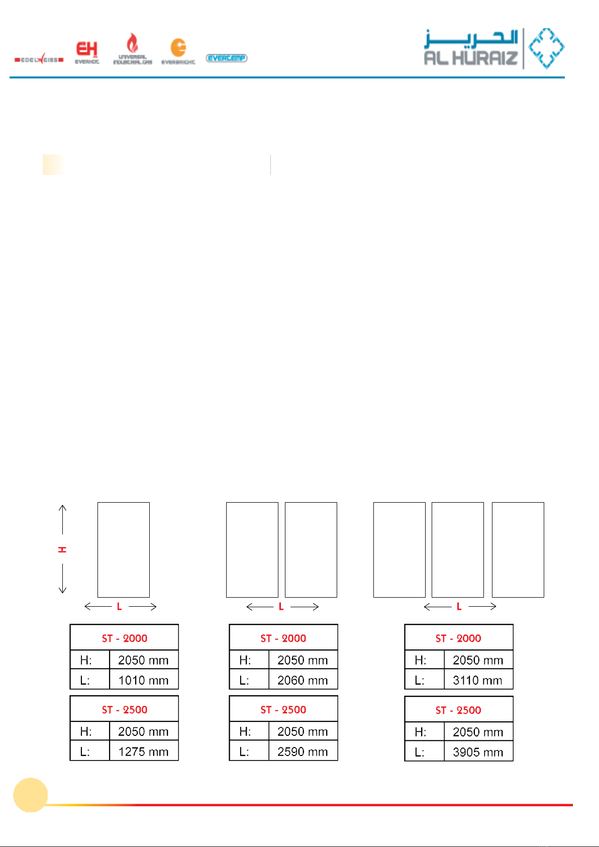
Dimensions of installed collectors
1Collector
2 Collectors
3 Collectors
.
8
Function

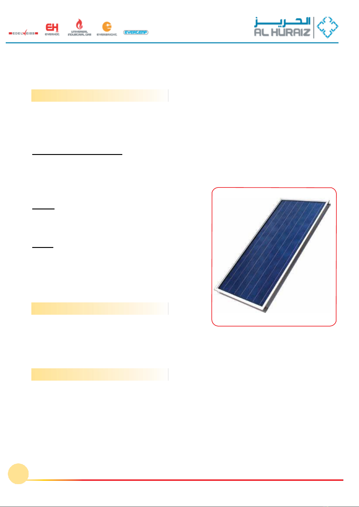
SOLARCOLLECTORSMODELSST-2000ANDST-2500
Collector with
black coating
Description
Flat solar collector, firmly built, of new
technology suitable for all forced circulation
solar systems. The production process and
the raw materials that are used produce a
high thermal energy efficiency even during
periods with insufficient radiation.
Models
The solar collectors EVERHOT are produced
in two types, ST-2000 (2,10 m2) and ST-2500
(2,61 m2), with blue titanium selective absorber
or black selective coating which either in solo
or in combinations cover all of the
requirements of solar systems.
•Frame made from anodized aluminum, which is extremely durable to adverse climatic
conditions (high humidity - coastal areas).
•Strong side and back insulation (20mm glass wool and 40mm rock wool), minimize
Thermal losses in areas with low seasonal temperatures.
•Special prismatic glass, resistant to hale (solar tempered glass).
•Absorber made from one unique sheet absorber with blue colour titanium selective
coating or with black selective coating. The absorber with titanium coating is ideal for
regions with high diffused radiation and low temperatures, absorbing up to 16% more
solar radiation in winter months compared to simple black chrome absorbers. This
method of coating is non toxic and does not pollute the environment, while keeping
stable its mechanical and optical properties during high and low temperatures.
TyPE
SElECTIVE
Dimensions
(m2)
Gross
Surface
(m2)
Net
Surface
(m2)
weight
(kg)
Capacity
(l)
Test
Pressure
(bar)
max. working
Pressure
(bar)
absorber
a
e
ST-2000
2050x1010x90
2,10
1,80
43
1,67
10
7
95%±2%
5%±3%
ST-2500
2050x1275x90
2,61
2,31
51
2,09
10
7
9
DIMENSIONS OF THE SOLAR COLLECTORS
Basic Technical Characteristics
SOLAR COLLECTORS MODELS ST-2000 AND ST-2500 SELECTIVES
Absorber: a unique sheet
Thermal Absorption: 95%
Thermal loss: 5%
Thickness: 0,2mm
Coating: selective titanium
Characteristics of the tubes:
Diameter of the horizontal tubes: (22mm)
Diameter of the vertical tubes: (10mm ou 8mm)
Material: copper
Test Pressure: 10 bars
Maximum functional pressure: 7 bars
Frame:
Material: anodized aluminum profile
Back insulation: 35-40 mm insulation
Side insulation: 20 mm glass wool
Cover:
Material: solar tempered glass
Thickness: 4mm
Water tightness: joint EPDM and transparent silicone
Total thermal efficiency: 95% ± 2%
Total thermal losses: 5% ± 3%
Antifreeze:
glycol
appropriate for
solar systems
The characteristics of the support base for the collector(s) with the ways of installation on the various
types of roofs, are described analytically on page 28 Installation Instructions.
.
10
Support base:
General Characteristics:
Technical C h a r a c t e r i s t i c s :
Collector
with titanium
selective treatment
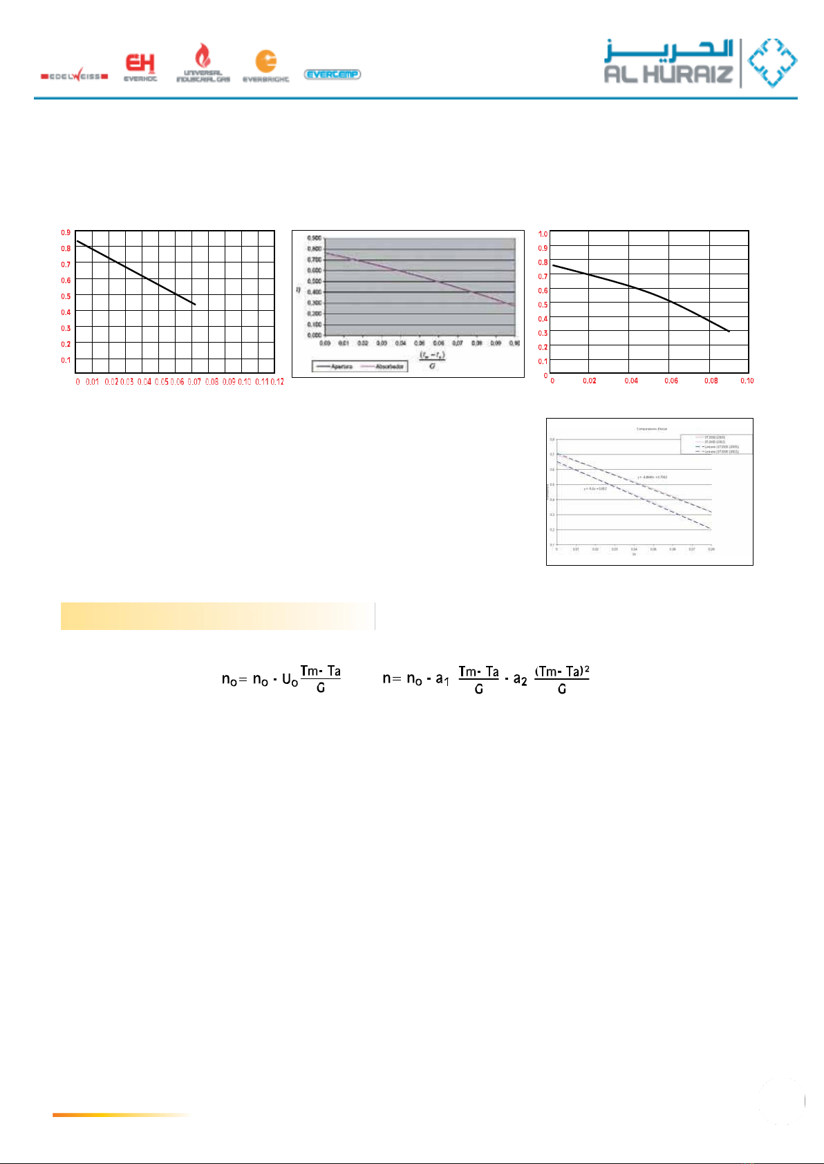
Efficiency curves of MEGASUN solar collectors
ST 2000 Selective (2,10m2
, 24 C)
ST2500Selective
SUN-POWER Selective
a.TestNr:1021 b.TestNr:30.0012.0-3 c.Test Nr28601068
•Curve a:
Test by DEMOKRITOS (Greece) n= 0,85 - 5,44 T*
•Curve b:
Test by CENER (Spain) n= 0,767-0,37 (tm - ta)/G
•Curve c:
Test by TÜV Bayern (Germany) n=0,794-3.907 T*- 0,0157 (m-L)T*
•Curve d:
Calculus CST Bat (France) y = -4,8648x + 0,7063
d.
Avis Technique 14/05-947
Procedure for the calculation of estimated energy output of collector
The collector instantaneous efficiency curve is expressed by the following relation in linear or second-order form:
where n is the collector instantaneous efficiency, Tm is the mean temperature of water inside the collector, in ºC, Ta is the
ambient air temperature, in ºC and G is the total solar radiation that falls in the collector, in W/m2. The parameters of the
above equations of the instantaneous efficiency curve n0 and U0 are determined by testing according to the standards EN
12975-2 and ISO 9806-1.
The estimated energy output of the collector is calculated using the values of parameters n0 and U0, as these have been
Determined by testing from several accredited laboratories of Europe, for a number of cities and under the following conditions:
- solar radiation, ambient air temperature and temperature of cold water (average monthly values as given in the tables of
the following page)
- Temperature of hot water delivered by the collector to the user equal to 45ºC and 40ºC.
For every day of the month the efficiency of the collector is calculated, where the maximum efficiency and the heat losses of
the collector are taken into account depending on the existing climatic conditions of the day and the desired temperature of
hot water delivered by the collector to the user. Also, the latitude of the area of installation and the slope of the collector are
taken into account. Following this, the mean monthly output of the collector is calculated using the climatic data of the month.
Finally, the sum of the mean monthly outputs of the collector gives the total annual output. It is noted that the values of the
estimated energy output of the collector that are calculated and given in the next tables are the maximum estimated and
therefore they are achieved only by the optimum design and installation of the solar collector and the solar system. This
means that that there must not be any shading of the collector during the hours of sunshine and operation of the system, any
water penetration inside the collector from the rain, any accumulation of water in the inside part of the collector cover, any
accumulation of dust or other substances on the outside part of the collector cover, any deformation of any part or area or
material of the collector and system, any leakage in the hydraulic connections in any part of the collector or system, bad or
no insulation of the piping of the solar system, bad operation of the valves of the solar system, non proper maintenance of
the collector and the system and problems caused by deposition of salts within the tubes of the collector by the usage water.
11
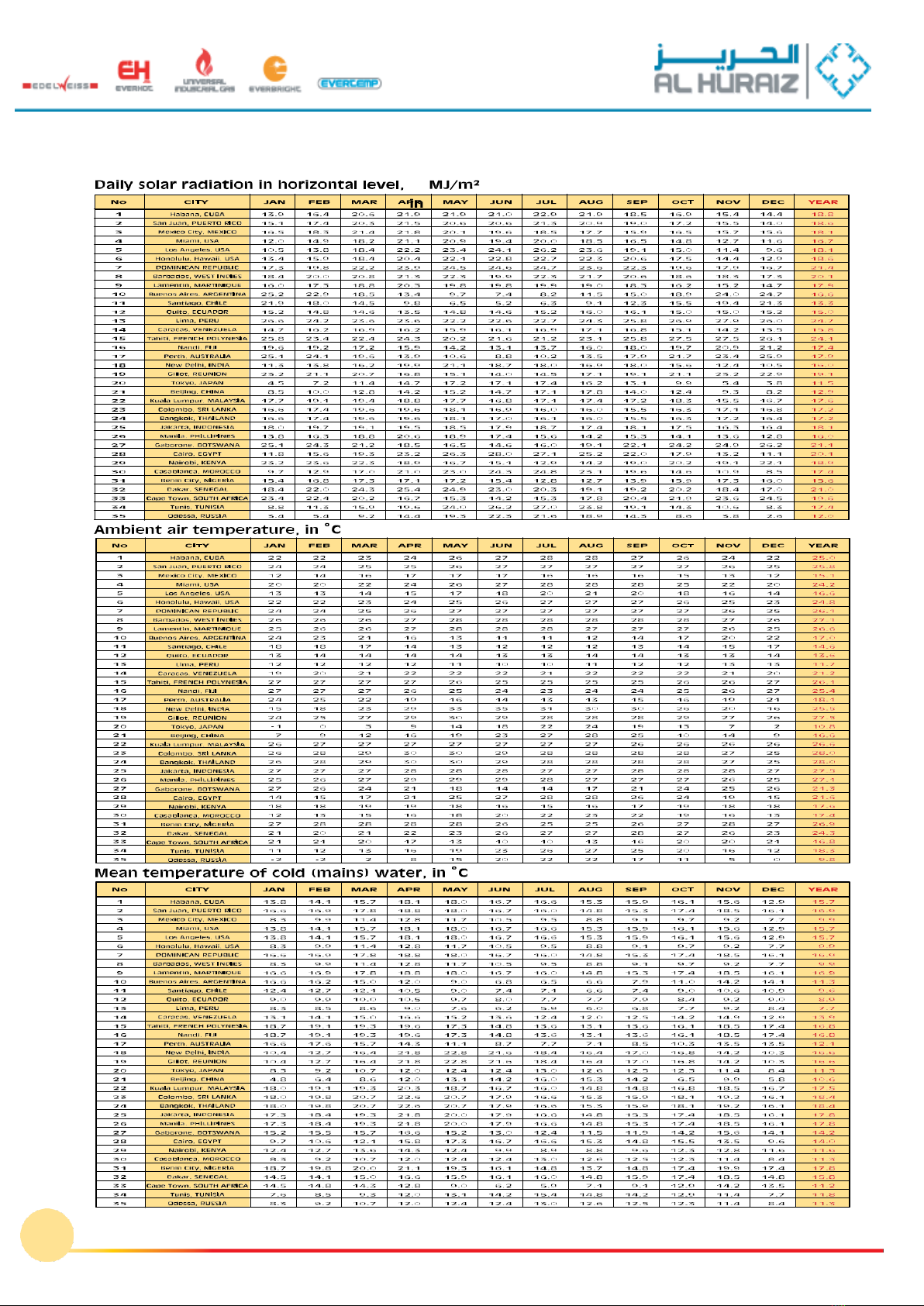
CLIMATIC DATA OF SELECTED WORLD CITIES
12
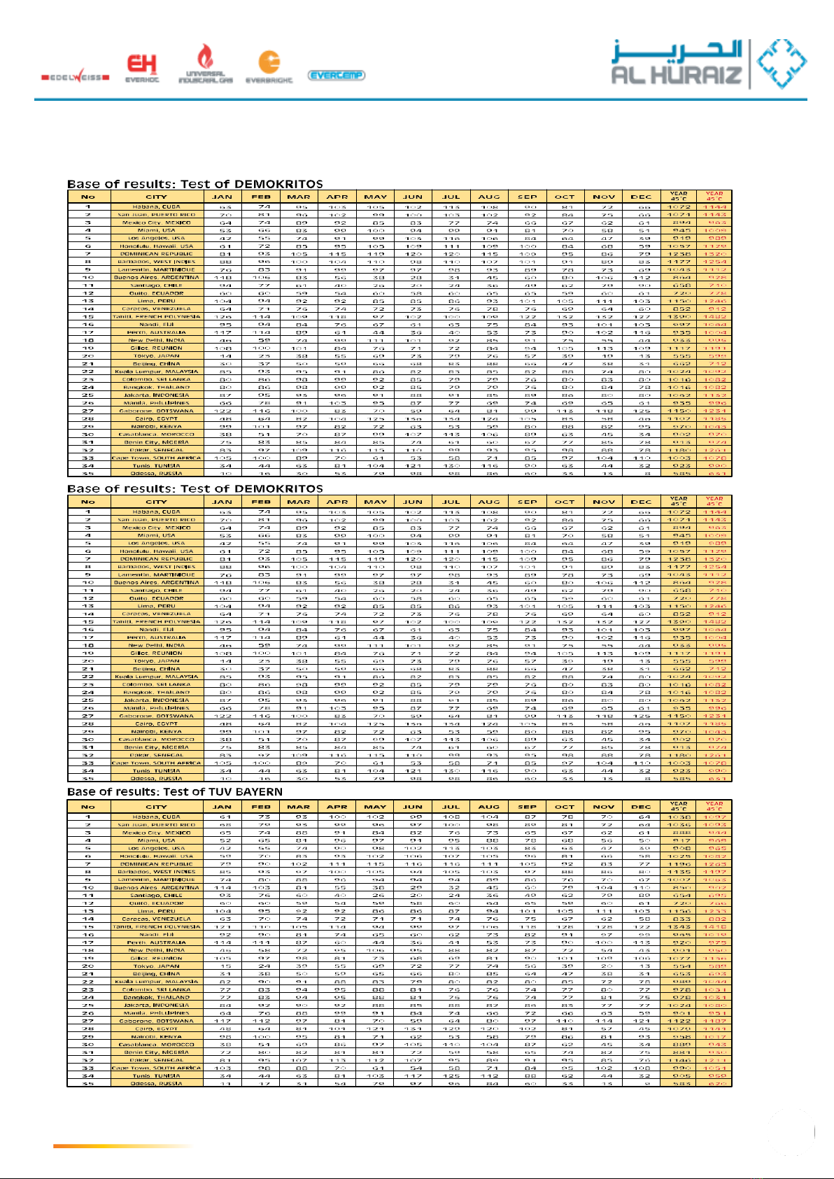
Energyoutputofthecollectorinseveralcitiesoftheworld(inkWh/m2)
13
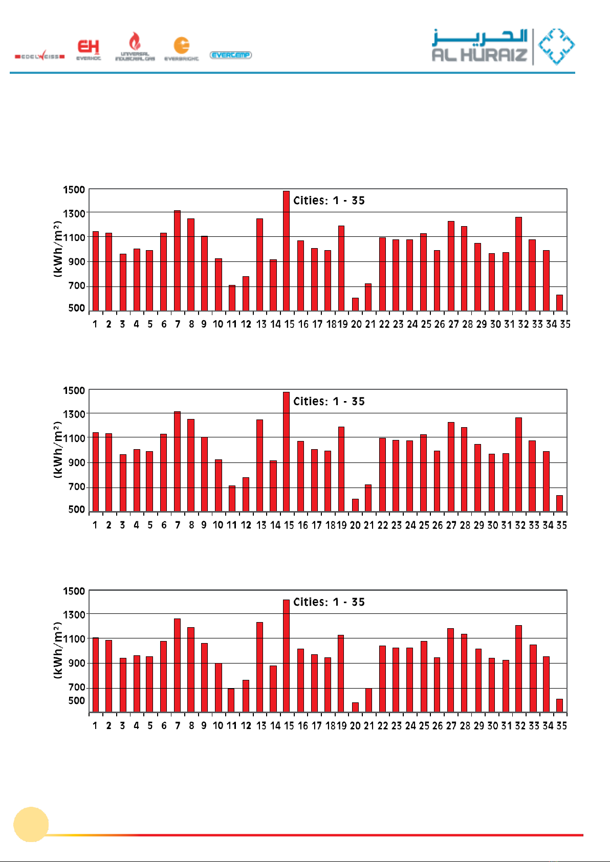
GRAPHICAL REPRESENTATION OF ENERGY OUTPUT OF COLLECTORS IN
SELECTED CITIES OFTHE WORLD (in KWh/m
2
), in temperature 40°C
Collector: ST 2000 selective- Base of results: Test of DEMOKRITOS, GREECE
Collector: ST 2000 selective- Base of results: Test of DEMOKRITOS, GREECE
Collector: ST 2000 selective (SUN-POWER) - Base of results: Test of TÜV BAYERN, GERMANY
14
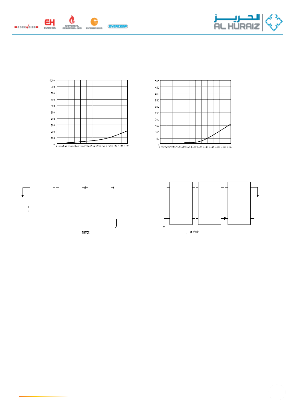
Pressuredropincollectors–Calculationsof DemokritosInstitute
Collector: ST 2000 selective (2,10 m2
,26 C)
Collector: ST 2500 selective (2,61 m2
, 24 C)
For the systems 150 –500, BL1 or BL2, the parallel connection of the solar
Collectors is recommended
In this case the pressure drop in one collector is about equal to the pressure
drop in the whole row of collectors for the supply that is equivalent to the total
of installed square meters.
The required flow of the pump for the forced circulation is approximately 40 - 80
liters / h for each installed square meter and depends on the design of each
installation.
Example:
For one system 300 E/BL1 with 3 collectors ST-2000 in a parallel connection,
total surface area 6,30m2, we can choose a medium flow rate of 60lt/h
per square meter of installed collectors. This means that the necessary flow
rate of the pump must be 60lt/hm2x6,30m2=378lt/h approximately. When
dividing by 3 (number of collectors), we obtain 126lt/h. When transforming to
liters/second (by dividing by 3.600) we will have 0,035 liters/second. From the
above graph of pressure drop of the collector St 2000, we estimate that
the flow rate of 0,035 liters/second corresponds to a pressure drop of
approximately 100 Pa.
15
hot
water
outlet
cold water inlet
or
hot
water
outlet
cold water inlet
Mass flowrate (Kg/s)
Mass flowrate (Kg/s)
Pressore
Drop
(PA)
Pressore
Drop
(PA)

Models
Models Bl1
(With1tubeheatexchanger)
Models Bl2
(With2tubeheatexchangers)
BoilerEVERHOT typeBL1andBL2with oneortwotubeheatexchangers
Technical C ha rac t er is t ic s
The EVERHOT boilers are manufactured according to European and German standards in the new
state of the art solar boilers manufacturing facility and offer absolute safety in operation, great
savings and a long lifespan. These tanks are for indoor use.
•Manufactured from extra thick and high quality USD 37.2 steel plate.
•Double tested for water tightness.
•The internal cleaning of the cylinder is not done chemically but in the most modern sand blasting
facility, resulting in the perfect addiction of the enameling on the steel surface.
•The enameling is made with double ‘direct’ enamel process and it is heated at a temperature of
850ºC.
•Supplied with a big magnesium rod DN 32mm for additional anti-
Corrosive protection.
•Side flange DN 115 mm. for easy cleaning (except for models 150).
•Top flange DN 115 mm for easy replacement of the magnesium rod.
•Optional electric resistance (2 - 9 KW).
•Available with one or two tube heat exchangers, suitable for every
Application
•Upon a special order, buffers can be delivered (150lt -1000lt models BL0) without a tube heat
exchanger.
model Insulation
Capacity
exterior
(litres)
model Insulation
Capacity
exterior
(litres)
150BL1
Yes
150
150BL2
Yes
150
200BL1
Yes
200
200BL2
Yes
200
300BL1
Yes
300
300BL2
Yes
300
420BL1
Yes
420
420BL2
Yes
420
500BL1
Yes
500
500BL2
Yes
500
800BL1
Yes
800
800BL2
Yes
800
1000BL1
Yes
1000
1000BL2
Yes
1000
Material: Steel plate USD37.2 quality
Welding: Robotically welded in inert gas
environment
Cleaning: 6 point metal blasting
Internal treatment: Glass enameling heated at 850°C
Function Pmax: 6 bar
Testing Pmax: 15 bar for 5 minutes
Function Tmax: +95° C
PVC in various colors
Material: Polyurethane CFC & FCKW Free
Density: 40 kg/m3
Thickness: 65 mm
(For storage tanks BL800 –BL1000 for all the models, the
insulation is made from flexible polyurethane 75 mm and is
detachable for easier passage during installation)
2 to 4 KW (230 V) with thermostat or 6KW or 9KW (400
V) without thermostat
Coil heat exchanger made of heavy duty steel tube 33mm
(tube)
.
16
Heat Exchanger Type:
Electrical Backup (upon request):
Insulation:
Tank:
Description
Outer Cover Material:

DESCRIPTION OF STORAGE TANKS
1.
Hotwateroutlet
2. Magnesium rod
3.
TopflangeΦ115
4.Sensorinlet
5. Recirculation connation
6.Electricback-upinlet
7.Collectorinlet
8.Sensorinlet
9.
Side flange Φ115
10. Collector outlet
11.
Coldwaterinlet
BL1
BL2
1.
Toplange Φ115
2. Magnesium rod
3. Hot water outlet
4. Back-up heat exchanger inlet
5. Sensor inlet
6. Recirculation connexion
7. Sensor inlet
8. Back-up heat exchanger outlet
9. Electric back-up inlet
10. Collector inlet
11. Sensor inlet
12. Collector outlet
13. Cold water inlet
14.
Side lange Φ115
Outer Cover material:
Color PVC jacket
Storage tanks weight empty (kg)
/External dimensions (mm):
* DIMENSIONS WITHOUT INSULATION
Thermal Insulation:
Polyurethane Foam CFC & FCKW free
Density: 40 kg/m3
Thickness: 65 mm.
Thermal Conductivity: 0,023 W/mk
Fire Class: Β3, auto extinguishable.
Hydraulic Connections Bl:
Corrosion Protection
Inner cleaning of the tank with automated sand
blasting (not chemically) resulting in a perfect
adherence of the enamel.
Food grade enamel quality applied with a
“double direct” method and baked at 850°C
(BUFFER tanks are excluded).
Extra corrosion protection is offered by
magnesium rods that must be checked and
replaced if necessary every 2 to 5 years,
depending on the quality of the water.
Backup Heating Source Using the Second,
Upper Heat Exchanger
Coil type heat exchanger, from heavy duty
steel (type Tube) integrated in the upper part
of the tank, in order for the secondary heating
source to heat only the upper part of the tank.
Further technical data concerning the upper
heat exchanger refer to the table concerning
BL2 tanks.
Volume
150 l
200 l
300 l
420 l
500 l
800 l
1000 l
Sensor
1/2"
1/2"
1/2"
1/2"
1/2"
1/2"
1/2"
Heat exchangers
1"
1"
1"
1 "
1 "
1 "
1 "
Hot-Cold inlets
1"
1"
1"
1 "
1 "
1 "
1 "
Electric Element
1 ½"
1½"
1½"
1½"
1½"
1½"
1½"
Recirculation
1"
1"
1"
1"
1"
1"
1"
ATTENTION:Tankshaveamaximumservicepressureof6bar.Itishighlyrecommendedtoinstalla6barTPValveandanexpansionvesselinthecoldinlet.
17
litter/
model
Bl1
Bl2
DIamETER
HEIGHT
150
64
69
603
1050
200
85
93
603
1400
300
108
128
603
1930
420
146
156
730
1730
500
165
182
730
1970
800
176
210
805*
945
1735*
1800
1000
201
235
805*
945
1985*
2050
Technical Specifications
model
Bl 150
Bl 200
Heat Exchangers
Solar (lower) Heat Exchanger
(Bl1 models)
Back-up Heat Exchanger
(Bl2 models)
Solar (lower) Heat Exchanger
(Bl1 models)
Back-up Heat Exchanger
(Bl2 models)
Heat Exchanger Capacity
lt
3.45
2.7
5.7
2.7
Heat Exchanger surface area
m2
0.6
0.5
1
0.5
lower Heat Exch. Flow Rate
m3/h
3
3
3
3
Pressure drop
mbar
65
52
120
60
Inlet temperature
° C
55
70
80
90
55
70
80
90
55
70
80
90
55
70
80
90
HeatExchangerPower*
Kw
7.8
15.6
20.4
25.5
4.7
9.4
12.3
15.4
10
20.5
26.5
33.7
4.7
9.4
12.3
15.4
Hot water continuous
supply
lt/h
190
385
500
625
115
232
303
380
250
500
650
830
115
232
303
380
Thermal losses **
Kwh/24H
1.2
1.65
model
Bl 300
Bl 420
Heat Exchangers
Solar (lower) Heat Exchanger
(Bl1 models)
Back-up Heat Exchanger
(Bl2 models)
Solar (lower) Heat Exchanger
(Bl1 models)
Back-up Heat Exchanger
(Bl2 models)
Heat Exchanger Capacity
lt
7.4
5.7
7.6
6
Heat Exchanger surface area
m2
1.4
1.2
1.5
1.3
lower Heat Exch. Flow Rate
m3/h
3
3
3
3
Pressure drop
mbar
150
130
155
140
Inlet temperature
° C
55
70
80
90
55
70
80
90
55
70
80
90
55
70
80
90
HeatExchangerPower*
Kw
12.3
25
32.6
41
11.8
23
30.5
38.3
14.2
27.5
36.6
46.4
12.8
23
34.5
37.5
Hot water continuous
supply
lt/h
300
620
800
1000
290
565
750
940
350
675
900
1150
315
567
850
982
Thermal losses **
Kwh/24H
2.24
2.68
model
Bl 500
Bl 800
Heat Exchangers
Solar (lower) Heat Exchanger
(Bl1 models)
Back-up Heat Exchanger
(Bl2 models)
Solar (lower) Heat Exchanger
(Bl1 models)
Back-upHeatExchanger
(Bl2 models)
Heat Exchanger Capacity
lt
11.5
6
11.5
6.3
Heat Exchanger surface area
m2
2.2
1.3
2.2
1.4
lower Heat Exch. Flow Rate
m3/h
3
3
3
3
Pressure drop
mbar
220
140
220
130
Inlet temperature
° C
55
70
80
90
55
70
80
90
55
70
80
90
55
70
80
90
HeatExchangerPower*
Kw
16.7
32.2
42.8
54.2
12.8
23
34.5
37.5
17
32
43
54
11.4
21
30.5
32.3
Hot water continuous
supply
lt/h
410
790
1050
1330
315
567
850
925
440
820
1100
1390
560
660
950
1010
Thermal losses **
Kwh/24H
2.91
3.22
model
Bl 1000
Heat Exchangers
Solar (lower) Heat Exchanger
(Bl1 models)
Back-up Heat Exchanger
(Bl2 models)
Heat Exchanger Capacity
lt
13.3
7.5
Heat Exchanger surface area
m2
2.5
1.4
lower Heat Exch. Flow Rate
m3/h
3
3
Pressure drop
mbar
250
145
Inlet temperature
° C
55
70
80
90
55
70
80
90
HeatExchangerPower*
Kw
20.5
40
53
65.5
12.3
25
32.6
41
Hot water continuous
supply
lt/h
500
980
1300
1600
415
845
1100
1390
Thermal losses **
Kwh/24H
3.6
*Cold water temperature 10°C. Hot water outlet temperature 45°C. Storage temperature 60°C.
** Water storage temperature 65°C –ambient temperature 20°C.
ATTENTION:Tankshaveamaximumservicepressureof6bar.It ishighlyrecommendedtoinstalla6barTPValveandanexpansionvesselinthecoldinlet.
18

Hydraulic kit
As a pump, regulator and air venting valve in solar heating systems.
With the hydraulic kit, hydraulic balancing, flow measurement and venting can be performed directly in
the station.
The built-in SETTER Inline UN allows the required quantity of fluid in the primary circuit to be exactly
and simply set and checked. The continuous venting system meets the most
demanding requirements and keeps the system free of air.
Systems which are correctly balanced hydraulically and air-free guarantee
optimal energy extraction, and are thus more cost-effective in the sense of the
energy-saving directives laid down by law.
Using the scale, which is pre-calibrated for glycol, the technician can set and
check the exact flow-rate values on-site. Neither training courses nor expen-
sive measuring devices are required. Installation and venting can be carried
out by one person working unaided.
The solar station must be mounted vertically to ensure problem-free function-
ing of the venting unit.
•Rugged
design
•Cost-effective installation and filling
•Multi-functional ball valve, which greatly simplifies the filling and draining of
the system
•Collector and reservoir sections can be separated for installation work
•Straightforward pump replacement (suction and pressure side can be shut off)
•Precise and rapid regulation adjustments, requiring no diagrams, tables or
expensive measuring devices
•Function checking using the direct flow rate indicator in theSETTER Inline UN
•Visual scale in l/min pre-calibrated for glycol mixes u=2.3 mm2/s
•Constant air release while system is running
•Straightforward venting directly in the station
•Can be connected to any readily-available controller
•Reliable operation, and maintenance-free
The flow-rate measurement is based on the proven principle of a baffle float.
The basis for the air venting are special flow technology measures which accumulate the air in the top
of the venting space, from where it can be released from time to time. At the same time, acts as a check
on whether air is building up in the system. There are no
Mechanical parts, so the design ensures a long service life.
19
Operation
Advantages
Installation position
Application
is
the medium flowing in the opp
all
Turning the handle 90º to the
flow and allows the upper sys
and drain cock.
Turning the ha
the me
b
handle the
can be sealed
u
nal closing.
disconnec-
etween the
vessel at
bleeder valve
tank is to
um flowing
to approx.
er valve for Precision adju
quantity to be
routed to the of balancing v
ion which balancing valv
ssed even required for th
is on. The the adjustmen
for easy indicator. The
mm
2
/s. T
The con
quantity of the the 1 1/2
check the
locations
Conne
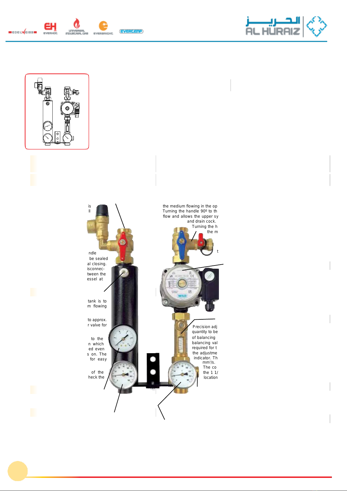
Hydraulic kit
1) Circulation pump
2) SETTER Inline UN
balancing valve
3) Venting tank with
bleeder valve
4) Bleeder valve
5) Pressure gage
6) Thermometer
7) Stop ball valve with
Safety valve
8) Stop ball valve with fill
and drain cock and
integrated check valve
9) Safety valve
10) Connector ADG for the
expansion vessel
11) Wall fixing
12) Packaging box
The ball valve allows the flow circuit line to be divided between the
collector and the heat accumulator. As required by safety
regulations, the connection between
the collector and safety valve
not interrupted in any of the b
valve positions.
The safety valve thus
protects the system
components a g a i n s t
excessive over-pressure in
all operating phases.
Holes are provided in the
of the ball valve so that it
to protect against un intentio
This prevents unintentional
tion of the connecting line b
collector and the expansion
this point.
Venting tank with
The purpose of the venting
remove air from the medi
through the tank.
The venting tank can hold up
2.5 dl of air and has a bleed
releasing the air.
The bleeder valve is
outside through the insulat
means that it can be acce
when the insulating casing
outlet has a suitable fitting
attachment of a hose.
The frequency and
collected air can be used to
leak tightness of the system
Pressuregage
The pressure gage with a range from 0 to
10 bar indicates the system pressure.
Thermometer
The thermometer with a range from 0 to 160ºC constantly indi-
cates the medium temperature in the flow circuit. The temperature
is recorded directly in the medium to minimize the reaction time.
The sensor is inserted in a protective pipe so that it can be
exchanged without having to empty the system.
The ball valve allows the return line to be split between the collector and the heat accu-
mulator. The special ball cock design provides various functions. If the handle is pointing
in the direction of flow the system medium can circulate. An integrated check valve stops
osite direction and also acts as a gravity brake.
right closes the ball cock in the direction of the medium
tem part (collector) to be filled and emptied using the fill
ndle 90º to the left closes the ball cock in the direction of
dium flow and allows the lower system part (reservoir) to
e filled using the fill and drain cock.
A male thread G 3/4” is provided on the fill and drain cock
for connecting a hose. Holes are provided in the handle of
ball valve so that it can be sealed to protect against
nintentional closing.
WILOST25/6-3circulationpump,solarversion
This circulation pump, included as standard in the scope
of delivery and integrated in the hydraulic kit, covers a
large delivery range.
The required operating point can be preselected using
one of the three levels.
A defective pump can be replaced without having to
empty the system using the stop cocks on the suction
side (Setter Inline UN) and the pressure side (ball valve).
SETTERInlineUNbalancingvalve
stment at the balancing valve allows the required delivery
adapted to system requirements. The proven combination
alve and flow indicator in one housing in the hydraulic kit
es means that no additional measuring components are
e SETTER Inline UN. Flow rate indication is constant, i.e.
t can be immediately verified by means via the flow rate
indicator is pre-calibrated for a medium viscosity of 2.3
his does away with the need for correction curves.
nection flange on the outlet side is directly screwed onto
”pump connector fittings which means there are no seal
for further adapter components.
ctorADG
The connector fitting with G 3/4” connecting thread for the expansion
vessel is connected in series with the circulation pump. This arrangement
prevents negative working pressure conditions in even critical systems and avoids reduc-
tions in the working pressure, one of the main causes of early evaporation of the medium.
Thermometer
The thermometer with a range from 0 to 160ºC constantly indicates the medium tempera-
ture of the flow circuit. The temperature is recorded directly in the medium to minimize
the reaction time.
The sensor is inserted in a protective pipe so that it can be exchanged without having to
empty the system.
20
Stopball valvewithfill and draincock
andintegratedcheckvalve
Stopballvalvewithsafetyvalve
(responsepressure 6bar)
Return circuit components
(pump side)
Flow circuit components
(venting side)
HYDRAULICKIT
This manual suits for next models
33
Table of contents
Popular Heating System manuals by other brands


Salda
Salda RIRS 400VE EKO 3.0 Technical manual

NuAire
NuAire XBOXER XBC Series Installation, operating and maintenance instructions

DEVI
DEVI Devifoil Mirror installation instructions

System air
System air VTR 100/B LITE user manual

OSTBERG
OSTBERG HERU 400 Series Installation

Etherma
Etherma 9120054178607 Installation and operating instructions


