EverMore ST-K700 User manual
GM-R700 User’s Manual
EverMore Technology Inc.
2F, No.7, R&D Road 1, Science-Based Industrial Park, Hsinchu, Taiwan, 300, R.O.C.
1
ST-K700/ GM-R700
GPS Receiver User’s Manual
EverMoreTechnologyInc.

GM-R700 User’s Manual
EverMore Technology Inc.
2F, No.7, R&D Road 1, Science-Based Industrial Park, Hsinchu, Taiwan, 300, R.O.C.
2
© EverMore Technology Inc. All rights reserved.
Not to be reproduced in whole or part for any purpose without written permission of EverMore Technology Inc.
Information provided by EverMore Technology Inc. is believed to be accurate and reliable. However, no
responsibility is assumed by EverMore Technology Inc. for its use. EverMore Technology Inc. reserves the right to
change specification at any time without notice.

GM-R700 User’s Manual
EverMore Technology Inc.
2F, No.7, R&D Road 1, Science-Based Industrial Park, Hsinchu, Taiwan, 300, R.O.C.
3
Contents
1. INTRODUCTION............................................................................................... 5
1.1 Overview ............................................................................................................................. 5
1.2 Features ............................................................................................................................... 6
1.3 Applications......................................................................................................................... 6
1.4 Start-up Modes ................................................................................................................... 7
2. TECHNICAL SPECIFICATIONS................................................................... 8
2.1 Electrical Characteristics ..................................................................................................8
2.2 Environmental Characteristics ......................................................................................... 9
2.3 Physical Characteristics..................................................................................................... 9
3. HARDWARE INTERFACE ........................................................................... 10
3.1 ST-K700 PS/2 Female Connector (standard type) ........................................................ 10
3.2 ST-K700 Female PS/2 Connector Interface ................................................................... 11
3.3 ST-K700 Accessories.........................................................................................................12
3.3.1 DB9 9 Pins Female and PS/2 Male Connector .................................................................. 12
3.3.2 USB Connector .............................................................................................................. 13
3.4 ST-K700 Dimensions ........................................................................................................ 14
3.5 ST-K700 Appearance Diagram ....................................................................................... 14
4 ST-K700 USB DRIVER INSTALLATION.................................................... 15
5. OPERATION AND TEST .............................................................................. 16

GM-R700 User’s Manual
EverMore Technology Inc.
2F, No.7, R&D Road 1, Science-Based Industrial Park, Hsinchu, Taiwan, 300, R.O.C.
4
6. SOFTWARE SPECIFICATION .................................................................... 17
6.1 ST-K700 NMEA Protocol................................................................................................. 17
6.2 General NMEA Format ................................................................................................... 17
6.3 $GPGGA ........................................................................................................................... 18
6.4 $GPGLL............................................................................................................................ 19
6.5 $GPGSA ............................................................................................................................ 19
6.6 $GPGSV ............................................................................................................................ 20
6.7 $GPRMC........................................................................................................................... 21
6.8 $GPVTG............................................................................................................................ 21
6.9 $GPZDA............................................................................................................................ 22
7. LIMITED WARRANTY................................................................................... 22
8. ORDERING INFORMATION ........................................................................ 23
8.1 Standard Type Cable (Female PS/2)............................................................................... 23
8.2 Optional Types Cable....................................................................................................... 24
8.2.1 Male PS/2 Cable............................................................................................................. 24
8.2.2 SP6P Cable .................................................................................................................... 25
8.2.3 RS-232 Cable (DB9 9 Pins Female + PS/2 Male).............................................................. 26
8.2.4 USB Cable (With USB Bridge Controller IC) ................................................................... 27
8.3 Car Charger List .............................................................................................................. 28
9. SERIES PRODUCTS INFORMATION....................................................... 29

GM-R700 User’s Manual
EverMore Technology Inc.
2F, No.7, R&D Road 1, Science-Based Industrial Park, Hsinchu, Taiwan, 300, R.O.C.
5
10. APPENDIX ................................... FEHLER! TEXTMARKE NICHT DEFINIERT.
1. Introduction
1.1 Overview
EverMore series GPS module ST-K700 is a high sensitivity ultra low power consumption cost
efficient, compact size; plug & play GPS module board designed for a broad spectrum of OEM system
applications. This product is based on the proven technology found in 16 channel GPS receivers and
NEMERIX chipset solution. The GPS module receiver will track up to 16 satellites at a time while
providing fast time-to-first-fix and 1Hz navigation updates. It is far reaching capability meets the
sensitivity & accuracy requirements of car navigation as well as other location-based applications,
such as AVL system. Handheld navigator, PDA, pocket PC, or any battery operated navigation system.
The ST-K700 design utilizes the latest surface mount technology and high level circuit
integration to achieve superior performance while minimizing dimension and power consumption. This
hardware capability combined with software intelligence makes the board easy to be integrated and
used in all kinds of navigation applications or products. The module communicates with application
system via RS-232 level with NMEA0183 protocol.

GM-R700 User’s Manual
EverMore Technology Inc.
2F, No.7, R&D Road 1, Science-Based Industrial Park, Hsinchu, Taiwan, 300, R.O.C.
6
1.2 Features
The ST-K700 GPS engine board offers following features:
zBuilt-in high performance NEMERIX chipset.
zAverage Cold Start in 50 seconds.
zUltra low power consumption.
z16 channels “All-in-View” tracking.
zSupport standard NMEA-0183 V3.0
zMulti-path mitigation hardware
zOptimum clock drift adjustment
zBuilt-in patch antenna
zOn-board rechargeable battery sustained real-time clock and memory for fast satellite
acquisition during power-up
zCompact board Size ST-K700 51mm x 42.5mm x 17.3mm (2.01”x1.67”x0.68”)
for easy integration into hand-held device.
1.3 Applications
ST-K700 engine board receiver is a high performance, ultra low power consumption, plug &play
product. These applications are as follow.
zCar navigation system for portable device and car device
zWrist watch
zSolar operated device
zMarine Navigation
zFleet management
zAVL and location-based services
zRadar detector with GPS function
zHand-held device for personal positioning and navigation
zIdeal for PDA, pocket PC and other computing devices at GPS application
zAsset tracking
zTiming reference

GM-R700 User’s Manual
EverMore Technology Inc.
2F, No.7, R&D Road 1, Science-Based Industrial Park, Hsinchu, Taiwan, 300, R.O.C.
7
1.4 Start-up Modes
Definitions
DESCRIPTION
Cold Start
The Cold Start takes the longest startup time among EMT GPS receivers. In
this scenario, the receiver has no acknowledgment on the last position, time,
and satellite constellation. The receiver is initiated to search blindly for satellite
signals in the cold start mode.
A
nother situation is that when no backup battery is connected, the GPS
receiver will be in the cold start mode and there is no data stored in SRAM.
Execute cold start of the test tool when first use. By this way can speed up
position fix time.
Warm Start
In this scenario, the receiver was off less than one week but more than 2-hour
time.
The receiver knows its last position, time and almanac because it has a
backup battery to keep current almanac, position and time stored in SRAM.
In the warm start mode, the receiver can quickly acquire satellites and get a
position fix faster than it does in the cold start mode.
Hot Start
In this scenario, the receiver was off less than 2-hour time. With the back up
battery connected and the current almanac, position, time and ephemeris
stored in SRAM, the receiver applies its last ephemeris data to calculate and
get a position fix.
Reacquisition
In the reacquisition mode, the receiver takes time to lock on satellites if
buildings or obstacles are blocking the signals for a short while.
This is very common in urban areas, but please be noted that reacquisition
time has nothing to do with the time-to-first-fix (TTFF).

GM-R700 User’s Manual
EverMore Technology Inc.
2F, No.7, R&D Road 1, Science-Based Industrial Park, Hsinchu, Taiwan, 300, R.O.C.
8
2. Technical Specifications
2.1 Electrical Characteristics
2.1.1 General
Frequency L1, 1575.42 MHz
C/A code 1.023 MHz chip rate
Channels 16
2.1.2 Sensitivity
Tracking -152dBm type
2.1.3 Accuracy
Position 3-25 meters CEP (90%) horizontal, SA off.
Velocity 0.1 meters/second
Time ±100 ns synchronized to GPS time
2.1.4 Datum
Default WGS-84
Other Support different datum by request
2.1.5 Acquisition Rate (Open sky, stationary requirements)
Hot start 7 sec, average
Warm start 38 sec, average
Cold start 50 sec, average
2.1.6 Dynamic Conditions
Altitude 18,000 meters max
Horizontal Velocity 300 kilometers/hour max
Vertical Velocity 36 kilometers/hour max
Acceleration 2g, max
Jerk 4 meters/second3, max

GM-R700 User’s Manual
EverMore Technology Inc.
2F, No.7, R&D Road 1, Science-Based Industrial Park, Hsinchu, Taiwan, 300, R.O.C.
9
2.1.7 Power
Main power input 5V ± 0.5Vp-p DC input.
Supply Current Typical 33 mA
2.1.8 Serial Port
Electrical interface one full duplex serial communication, RS-232 interface
Protocol message NMEA-0183, version 3.0
Default NMEA GGA, GSA, GSV, RMC and VTG. 9600 baud rate,
8 bits data, 1 start, 1 stop, no parity.
(Option baud rate: 4800,19200, 38400)
2.2 Environmental Characteristics
Operating temperature range -40 ℃to +80 ℃
Storage temperature range -50 ℃to +90 ℃
2.3 Physical Characteristics
Dimension: 51mm x 42.5mm x 17.3mm (2.01”x1.67”x0.68”)
Weight: 78g (2.75oz)
Interface connector: PS/2 female connector

GM-R700 User’s Manual
EverMore Technology Inc.
2F, No.7, R&D Road 1, Science-Based Industrial Park, Hsinchu, Taiwan, 300, R.O.C.
10
3. Hardware Interface
3.1 ST-K700 PS/2 Female Connector (standard type)
ST-K700 Real Picture
PS/2 Female Connector Pin Assignment
Pin Function Input/Output Level
1 VCC Power Supply 5V
2 GND
3 RX Input 12V, RS232
4 RXD Input 3.3V, LVTTL
5 TXD Output 3.3V, LVTTL
6 TX Output 12V, RS232
3RX 5
TXD
1VCC
PS/2(Female)
2GND attheST-K700
4RXD 6
TX
PS/2 female connector (standard type)
GM-R700 User’s Manual
EverMore Technology Inc.
2F, No.7, R&D Road 1, Science-Based Industrial Park, Hsinchu, Taiwan, 300, R.O.C.
11
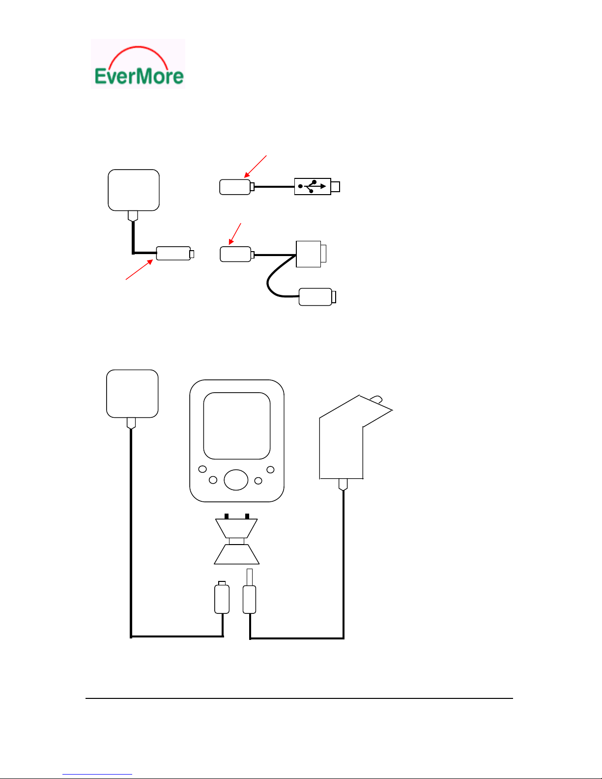
3.2 ST-K700 Female PS/2 Connector Interface
ExtensionMalePS/2Connector
ST-K700 USB, Link to PC or Notebook
GPS 1M
ExtensionMalePS/2Connector
2M 1M
RS232, Link to PC or Notebook
Standard Female PS/2 Connector
MalePS/2
ST-K700 Link to Host Device Diagram
ST-K700
GPS DC12V
PDA
Car
Charger
Transition
Connecter
FemalePS/2
Connecter
ST-K700 Link to PDA Diagram

GM-R700 User’s Manual
EverMore Technology Inc.
2F, No.7, R&D Road 1, Science-Based Industrial Park, Hsinchu, Taiwan, 300, R.O.C.
12
3.3 ST-K700 Accessories
3.3.1 DB9 9 Pins Female and PS/2 Male Connector
DB9 Connector (Female)
Pin Function Input/Output Level
1 NC
2 TX Output RS232
3 RX Input RS232
4 NC
5 GND Ground 0V
6 NC
7 NC
8 NC
9 NC
9 5 3 5
DB9 1
RS232 PS/2 (Male)
(Female) 2
6 1 4 6
Connector Pin Assignment
PS/2 Connector (Male)
Pin Function Pin Function Pin Function
1 NC 3 GND 5 NC
2 NC 4 VCC 6 NC
GM-R700 User’s Manual
EverMore Technology Inc.
2F, No.7, R&D Road 1, Science-Based Industrial Park, Hsinchu, Taiwan, 300, R.O.C.
13
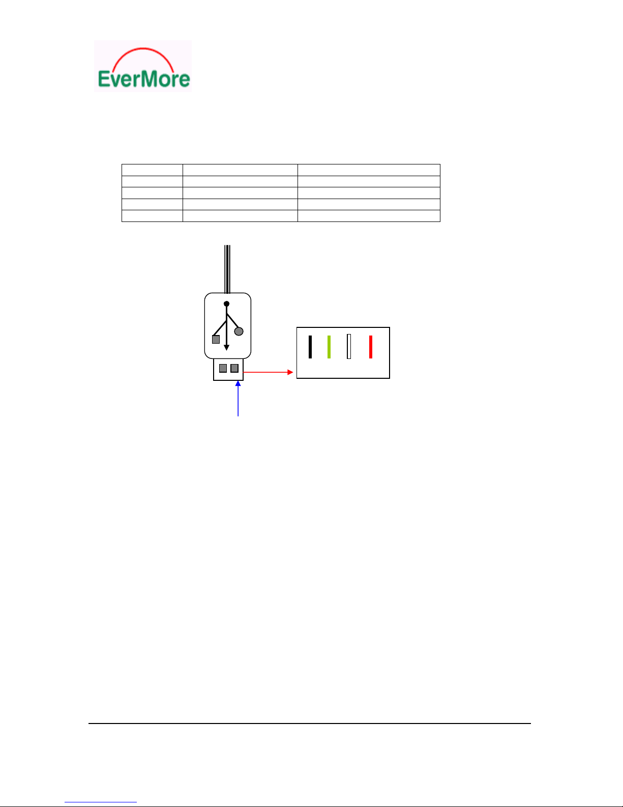
3.3.2 USB Connector
Pin Function Color
1 VCC, 5V Red
2 D- White
3 D+ Green
4 GND Black
GND D+ D- VCC
USBConnector Pin 4 3 2 1
Pin1
Connector Pin Assignment
GM-R700 User’s Manual
EverMore Technology Inc.
2F, No.7, R&D Road 1, Science-Based Industrial Park, Hsinchu, Taiwan, 300, R.O.C.
14
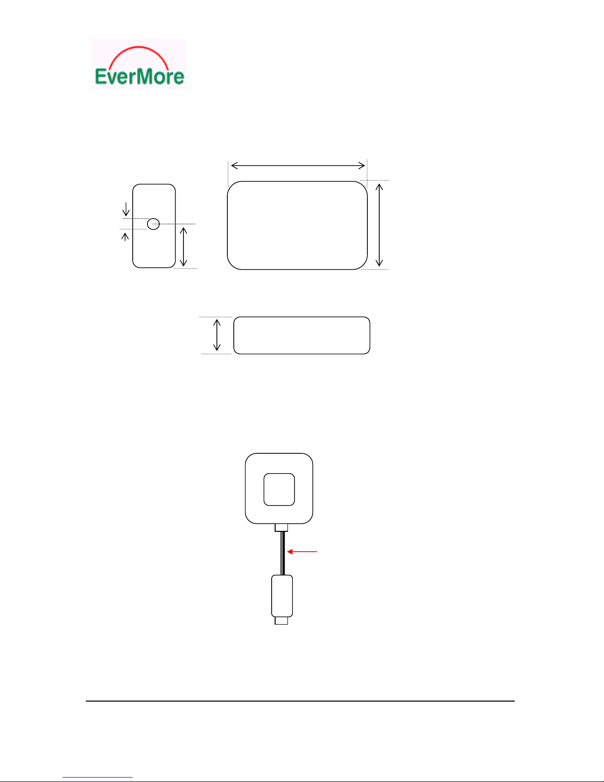
3.4 ST-K700 Dimensions
Length 51
Unit:mm
Diameter Wide
5.8 42.5
41.25
TopView
17.3
Height
LateralView
3.5 ST-K700 Appearance Diagram
GPSReceiver Patch
Ant
Length: 2M
PS/2(Female)
ST-K700
GM-R700 User’s Manual
EverMore Technology Inc.
2F, No.7, R&D Road 1, Science-Based Industrial Park, Hsinchu, Taiwan, 300, R.O.C.
15
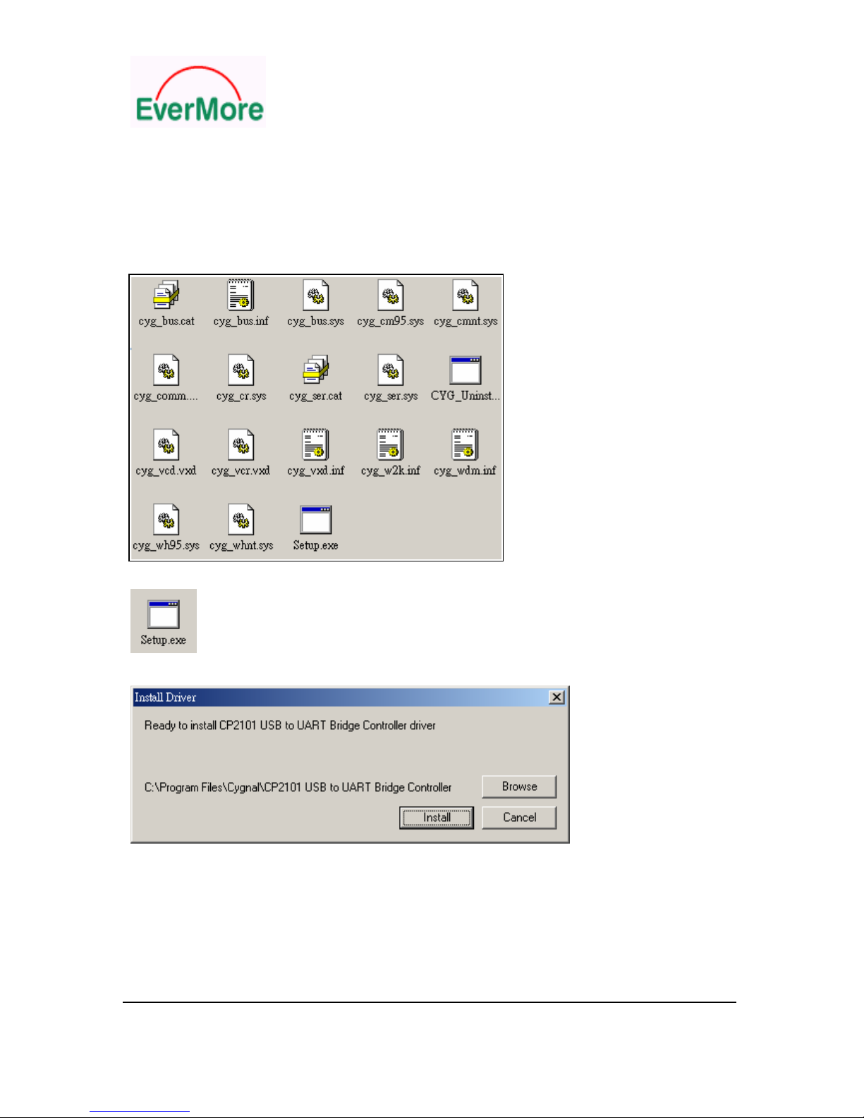
4 ST-K700 USB Driver Installation
Following is the brief indication of USB driver installation. We enclose a CD for detailed USB driver
installation “GPS USB Driver Setup.pdf ” with products.
Step 1: Copy entire USB driver folder from CD to hard disk
Step 2: Double click the “ Setup.exe ” icon
Step 3: Press “Install” button
Step 4: Press “OK” button
Step 5: Restart PC system
Step 6: Plug-in GPS to PC USB port
Step 7 Check enable COM port number
GM-R700 User’s Manual
EverMore Technology Inc.
2F, No.7, R&D Road 1, Science-Based Industrial Park, Hsinchu, Taiwan, 300, R.O.C.
16
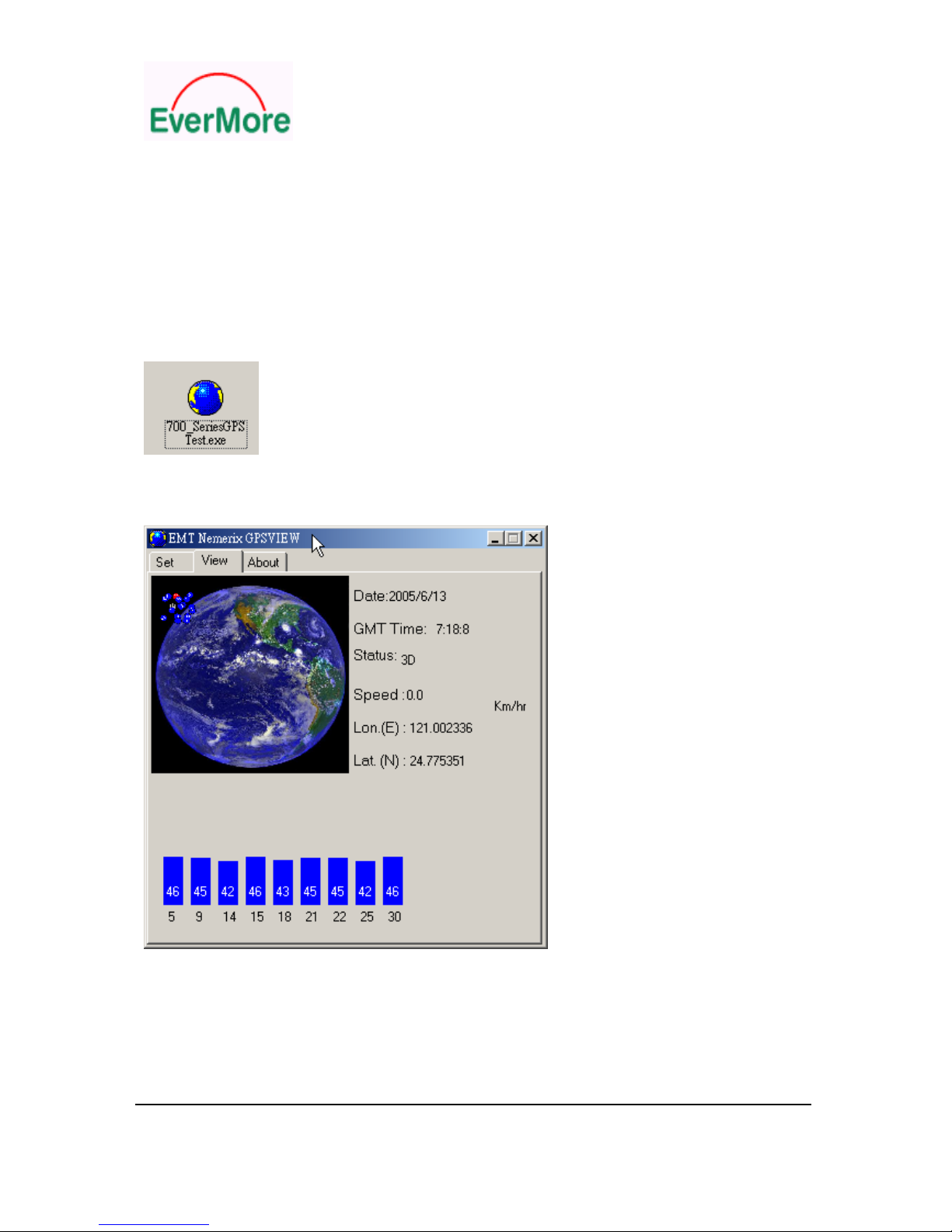
5. Operation and Test
The customers can change the data protocol and communication data baud rate for your application
using these tools. The software and manual are available for download from website.
Below list ST-K700 software tools
For example double click 700_SeriesGPSTest.exe to test ST-K700

GM-R700 User’s Manual
EverMore Technology Inc.
2F, No.7, R&D Road 1, Science-Based Industrial Park, Hsinchu, Taiwan, 300, R.O.C.
17
6. Software Specification
6.1 ST-K700 NMEA Protocol
The ST-K700 software is capable of supporting the following NMEA message formats
NMEA Message
Prefix
Format Direction
$GPGGA(1)*GPS fix data. Out
$GPGLL Geographic position Latitude / Longitude. Out
$GPGSA(3)*GNSS DOP and actives satellites Out
$GPGSV(3)*Satellites in view. Out
$GPRMC(1)*Recommended minimum specific GNSS data. Out
$GPVTG(1)*Velocity and track over ground. Out
$GPZDA Date and time. Out
*: (1): 1sec output 1msg , (3): 3sec output 1msg , 9600 baud rate (Standard output)
6.2 General NMEA Format
The general NMEA format consists of an ASCII string commencing with a ‘$’ character and
terminating with a <CR><LF> sequence. NMEA standard messages commence with ‘GP’ then a
3-letter message identifier. The message header is followed by a comma delimited list of fields
optionally terminated with a checksum consisting of an asterix ‘*’ and a 2 digit hex value representing
the checksum. There is no comma preceding the checksum field. When present, the checksum is
calculated as a bitwise exclusive of the characters between the ‘$’ and ‘*’. As an ASCII representation,
the number of digits in each number will vary depending on the number and precision, hence the
record length will vary. Certain fields may be omitted if they are not used, in which case the field
position is reserved using commas to ensure correct interpretation of subsequent fields.
The tables below indicate the maximum and minimum widths of the fields to allow for buffer size
allocation.

GM-R700 User’s Manual
EverMore Technology Inc.
2F, No.7, R&D Road 1, Science-Based Industrial Park, Hsinchu, Taiwan, 300, R.O.C.
18
6.3 $GPGGA
This message transfers global positioning system fix data. The $GPGGA message structure is shown
below:
Field Format Min
chars
Max
chars
Notes
Message
ID
$GPGGA 6 6 GGA protocol header.
UTC Time hhmmss.sss 2,2,2.3 2,2,2.3 Fix time to 1ms accuracy.
Latitude float 3,2.4 3,2.4 Degrees * 100 + minutes.
N/S
Indicator
char 1 1 N=north or S=south
Longitude float 3,2.4 3,2.4 Degree * 100 + minutes.
E/W
indicator
Char 1 1 E=east or W=west
Position Fix
Indictor
Int 1 1 0: Fix not available or invalid.
1: GPS SPS mode. Fix available.
Satellites
Used
Int 2 2 Number of satellites used to calculate fix.
HDOP Float 1.1 3.1 Horizontal Dilution of Precision.
MSL
Altitude
Float 1.1 5.1 Altitude above mean seal level
Units Char 1 1 M Stands for “meters”.
Geoid
Separation
Int (0) 1 4 Separation from Geoids can be blank.
Units Char 1 1 M Stands for “meters”.
Age of
Differential
Corrections
int (0) 1 5 Age in seconds Blank (Null) fields when DGPS
is not used.
Diff
Reference
Corrections
int 4 4 0000.
Checksum *xx (0) 3 3 2 digits.
Message
terminator
<CR> <LF> 2 2 ASCII 13, ASCII 10.

GM-R700 User’s Manual
EverMore Technology Inc.
2F, No.7, R&D Road 1, Science-Based Industrial Park, Hsinchu, Taiwan, 300, R.O.C.
19
6.4 $GPGLL
This message transfers Geographic position, Latitude, Longitude, and time. The $GPGLL message
structure is shown below:
Field Format Min
chars
Max
chars
Notes
Message ID $GPGLL 6 6 GLL protocol header.
Latitude Float 1,2.1 3,2.4 Degree * 100 + minutes.
N/S Indicator Char 1 1 N=north or S=south.
Longitude Float 1,2.1 3,2.4 Degree * 100 + minutes.
E/W indicator Character 1 1 E=east or W=west.
UTC Time hhmmss.sss 1,2,2.1 2,2,2.3 Fix time to 1ms accuracy.
Status Char 1 1 A Data Valid.
V Data invalid.
Mode Indicator Char 1 1 A Autonomous
Checksum *xx (0) 3 3 2 digits.
Message terminator <CR><LF> 2 2 ASCII 13, ASCII 10.
6.5 $GPGSA
This message transfers DOP and active satellites information. The $GPGSA message structure is
shown below:
Field Format Min
chars
Max
chars
Notes
Message ID $GPGSA 6 6 GSA protocol header.
Mode Char 1 1 MÎManual, forced to operate in
selected mode.
AÎAutomatic switching between
modes.
Mode Int 1 1 1Î.Fix not available.
2Î2D position fix.
3Î3D position fix.
Satellites Used Int 2 2 SV on channel 1.
Satellites Used Int 2 2 SV on channel 2.
… . .. .. ..
Satellites Used Int 2 2 SV on channel 12.
PDOP Float 1.1 3.1
HDOP Float 1.1 3.1
VDOP Float 1.1 3.1
Checksum *xx 0 3 2 digits
Message
terminator
<CR> <LF> 2 2 ASCII 13, ASCII 10

GM-R700 User’s Manual
EverMore Technology Inc.
2F, No.7, R&D Road 1, Science-Based Industrial Park, Hsinchu, Taiwan, 300, R.O.C.
20
6.6 $GPGSV
This message transfers information about satellites in view. The $GPGSV message structure is shown
below. Each record contains the information for up to 4 channels, allowing up to 12 satellites in view. In
the final record of the sequence the unused channel fields are left blank with commas to indicate that a
field has been omitted.
Field Format Min
chars
Max
chars
Notes
Message ID $GPGSV 6 6 GSA protocol header.
Number of
messages
Int 1 1 Number of messages in the message
sequence from 1 to 3.
Message number Int 1 1 Sequence number of this message in
current sequence, form 1 to 3.
Satellites in view Int 1 2 Number of satellites currently in view.
Satellite Id Int 2 2 Satellite vehicle 1.
Elevation Int 1 3 Elevation of satellite in degrees.
Azimuth Int 1 3 Azimuth of satellite in degrees.
SNR Int (0) 1 2 Signal to noise ration in dBHz, null if the sv
is not in tracking.
Satellite Id Int 2 2 Satellite vehicle 2.
Elevation Int 1 3 Elevation of satellite in degrees.
Azimuth Int 1 3 Azimuth of satellite in degrees.
SNR Int (0) 1 2 Signal to noise ration in dBHz, null if the sv
is not in tracking.
Satellite Id Int 2 2 Satellite vehicle 3.
Elevation Int 1 3 Elevation of satellite in degrees.
Azimuth Int 1 3 Azimuth of satellite in degrees.
SNR Int (0) 1 2 Signal to noise ration in dBHz, null if the sv
is not in tracking.
Satellite Id Int 2 2 Satellite vehicle 4.
Elevation Int 1 3 Elevation of satellite in degrees.
Azimuth Int 1 3 Azimuth of satellite in degrees.
SNR Int (0) 1 2 Signal to noise ration in dBHz, null if the sv
is not in tracking.
Checksum *xx (0) 3 3 2 digits.
Message
terminator
<CR> <LF> 2 2 ASCII 13, ASCII 10.
This manual suits for next models
1
Table of contents
Other EverMore GPS manuals

EverMore
EverMore E-trace User manual

EverMore
EverMore SA-320 User manual

EverMore
EverMore GM-R900 User manual

EverMore
EverMore GM-307 User manual

EverMore
EverMore GM-X205 User manual

EverMore
EverMore EB-X315 User manual

EverMore
EverMore SA-320 User manual

EverMore
EverMore SA-320 User manual

EverMore
EverMore BT-R900 User manual

EverMore
EverMore EB-N701 User manual


