Eversolar Eversol-TL2100 User manual

Installation Instructions 1
Table of Contents
Table of Contents.........................................................................................................1
1 About this manual.....................................................................................................3
1.1 Validity ................................................................................................... 3
1.2 Target group .......................................................................................... 3
1.3 Retention of the manuals ...................................................................... 3
1.4 CE marking............................................................................................ 3
2 Safety instructions and regulations .........................................................................4
2.1 Technical rules....................................................................................... 4
2.2 Accident prevention regulations .......................................................... 4
3 Unpacking..................................................................................................................5
3.1 Scope of delivery.................................................................................... 5
3.2 Check for transport damage ................................................................ 5
4 Technical data ...........................................................................................................6
4.1 DC input data......................................................................................... 6
4.2 Output data............................................................................................ 6
4.3 Efficiency and safety equipment .......................................................... 7
4.4 General data........................................................................................... 7
5 Installation and startup ............................................................................................8
5.1 Selecting an appropriate place for installation ................................... 8
5.1.1 Dimensions and weight ................................................................................8
5.1.2 Ambient conditions ......................................................................................9
5.1.3 Position.......................................................................................................10

2 Installation Instructions
5.2 Installing the inverter.......................................................................... 10
5.3 Electrical connection ........................................................................... 13
5.3.1 Connection to the public grid (AC) ............................................................14
5.3.2 Connection to the PV generator (DC) ........................................................20
5.4 Startup.................................................................................................. 23
5.5 Communication ................................................................................... 23
5.5.1 Communication through RS232 .................................................................23
5.5.2 Communication through RS485 .................................................................25
5.6 Safety protection.................................................................................. 28
5.6.1 Grid voltage and frequency protection .......................................................28
5.6.2 Over temperature monitoring .....................................................................28
5.6.3 Ground fault current interruption (GFCI)...................................................29
5.6.4 Isolation fault detection ..............................................................................29
5.6.5 Earthing fault monitoring ...........................................................................29
5.6.6 Active anti-islanding protection .................................................................29
5.6.7 DC current injection monitoring.................................................................29
5.6.8 DC reverse polarity protection ...................................................................29
6 Contact.....................................................................................................................30

Installation Instructions 3
1 About this manual
1.1 Validity
This installation instructions describes the installation and startup of Eversolar New
Energy inverters of the type Eversol-TL2100, Eversol-TL3200, Eversol-TL4600,
Eversol-TL5400.
1.2 Target group
Only an authorized skilled electrician who is approved by the supply grid operator
may install and startup the inverter. This documentation contains important
information regarding installation of the system. Be sure to read this manual carefully
before installing.
1.3 Retention of the manuals
All documents for the Eversol and the installed components must be kept with the
system and available at all times.
1.4 CE marking
Type Normative reference
Eversol-TL2100/3200 EN50178, EN61000-6-1, EN61000-6-3, EN61000-6-2,
EN61000-6-4, EN61000-3-2, EN61000-3-3
Eversol-TL4600/5400 EN50178, EN61000-6-1, EN61000-6-3, EN61000-6-2,
EN61000-6-4, EN61000-3-12, EN61000-3-11

4 Installation Instructions
2 Safety instructions and regulations
2.1 Technical rules
Installation must be suited to the on-site conditions and comply with local regulations
and technical rules.
2.2 Accident prevention regulations
1. Only skilled electricians who have read and fully understood all safety
information contained in these operating and installation instructions, may install
the inverter.
2. The Eversol may only be operated with PV generators. Do not connect any other
source of energy to the Eversol.
3. All covers on the unit must remain closed during operation and all screws must be
tightened.
4. Be sure that the PV generator and inverter connect to the ground in order to
protect property and persons.
5. Before opening the cabinet, the solar inverter must be disconnected from the grid
and PV generator. You must wait at least five
minutes in order that the energy storage
capacitors are fully discharged during this
period after disconnecting the inverter from the
grid and PV generator.
Installation Instructions 5
3 Unpacking
3.1 Scope of delivery
Object Description Quantity
A Eversol inverter 1 pcs
B Ornamental plate 1 pcs
C MC IV-connectors including male
connector and female connector
2 pairs (for TL4600 and TL5400)
1 pair (for TL2100 and TL3200)
D AC connector 1 pcs
E Installation and operating
instructions 2 pcs
Please check all of the components carefully in the box. If something missing, contact
your dealer at once.
3.2 Check for transport damage
Thoroughly inspect the inverter upon delivery, if you discover any damage to the
packaging which indicates that the inverter may be damaged, inform the responsible
transport company immediately. We will be glad to assist you if required.
6 Installation Instructions
4 Technical data
4.1 DC input data
Type TL 2100 TL 3200 TL 4600 TL 5400
Max. PV-generator power [W] 2100 3200 4600 5400
Max. DC Voltage [V] 580 580 680 680
MPPT voltage range [V] 125 - 530 125 - 530 125 - 550 125 - 550
Turn off DC Voltage [V] 125 125 125 125
Max. DC current [A] 18 20 20 25
Nominal DC current [A] 16.2 18 18 22.5
Number of DC connection 1 1 2 2
Number of MPP trackers 1 1 1 2
DC-connection MC IV-connector
Turn on power [W] 10
4.2 Output data
Type TL 2100 TL 3200 TL 4600 TL 5400
AC connector Spring-clamp tech
Power connection Single phase
Rated AC power [W] 1800 2800 4000 4600
Max. AC Power [W] 1980 3080 4400 5060
Grid voltage range 187-264 V / 207-264
Grid frequency range 47.5-50.2 Hz / 47-50.5Hz
Rated current [A] 7.8 12.2 17.4 20.0
Max. current [A] 9.9 / 9.57 15.4 / 14.9 22 / 21.3 25.3 / 24.4
Power factor 0.99 0.99 0.99 0.99
Harmonic distortion (THD) at
rated output <2% <2% <2% <2%
Power consumption at night [W] <0.2 <0.2 <0.2 <0.2
Power consumption at standby [W] 6 6 6 6

Installation Instructions 7
4.3 Efficiency and safety equipment
Type TL 2100 TL 3200 TL 4600 TL 5400
Efficiency
Max. efficiency 97.1% 97.3% 97.5% 97.5%
Euro efficiency (at 360VDC) 96.5% 96.5% 97.0% 97.0%
MPPT adaptation efficiency 99.5% 99.5% 99.5% 99.5%
Safety equipment
Internal overvoltage protection Integrated
DC Insulation monitoring Integrated
Earth fault protection Integrated
Mains monitoring According to VDE 0126-1-1, GB, G83/1
Earth fault current monitoring According to VDE 0126-1-1, GB, G83/1
DC current monitoring According to VDE 0126-1-1, GB, G83/1
4.4 General data
Type TL 2100 TL 3200 TL 4600 TL 5400
Housing Aluminium housing for inside and outside installation
Operating temperature range -20°C to +60°C(up 40°C derating)
Relative humidity 0% to 98%, no condensation
Site altitude Up to 2000m without derating above sea level
IP protection type IP 65 according to IEC 60529
Isolation type Transformerless
Cooling concept Convection Regulated cooling
Noise level < 40 dBA
LED display 3
LCD display Backlight, 16×2 Character LCD
Data logger
Data communication interfaces RS232 and RS485
Standard warranty (option) 5 years

8 Installation Instructions
5 Installation and startup
5.1 Selecting an appropriate place for installation
Danger!
Danger of lethal injury due to fire or explosion!
The Eversol may become hot in normal operation.
Do not install the Eversol on flammable construction materials and
where flammable materials are stored.
Do not install the Eversol in areas where there is a risk of explosion.
Caution!
Danger of burns from hot housing components!
Install the Eversol so that it cannot be touched unintentional.
5.1.1 Dimensions and weight

Installation Instructions 9
Type Eversol-TL2100 Eversol-TL3200 Eversol-TL4600 Eversol-TL5400
Weight 19.9 kg 20.7 kg 21.4 kg 23.5 kg
5.1.2 Ambient conditions
1. The area where the units installed is as dry as possible in order to extend their
service life.
2. Ensure good access to the unit for installation or any service work that may later
be required.
3. Maintain the following minimum clearances around the unit:
4. If the wall is wooden, please add a thermal insulating layer between Eversol
inverter and the wooden wall.
5. Do not expose the Eversol to direct sunlight, in order to avoid power reduction
due to excessive heating. That the ambient temperature keeps below 40 oC will
guarantee the Eversol working in optimal status.
6. Provide better ventilation for Eversol to ensure that heat is dissipated adequately.
7. Install Eversol on a solid surface. Because of the noises made by the Eversol
when in operating, do not install the unit on plasterboard walls in order to avoid
audible vibrations.
Direction Minimum clearance
above 30 cm
below 30 cm
sides 30 cm
10 Installation Instructions
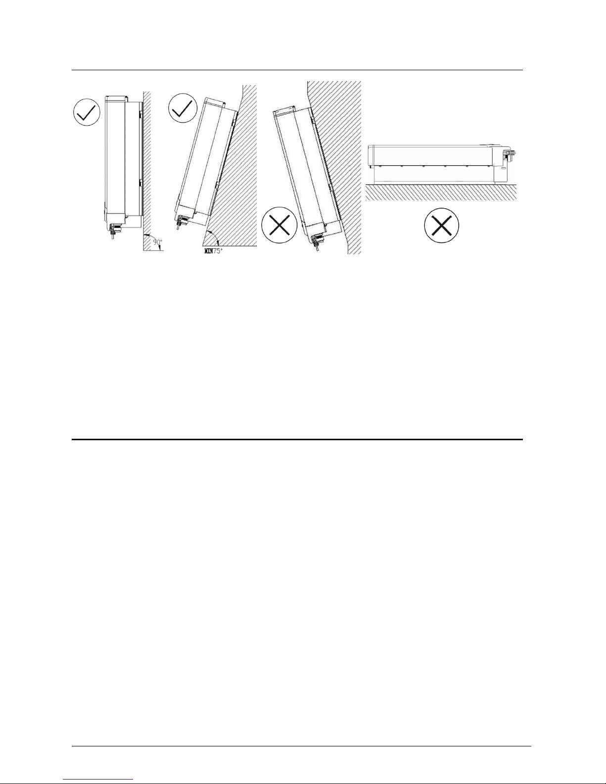
5.1.3 Position
1. The unit has been designed for vertical or tilted backwards by max. 15°
installation.
2. Do not install the Eversol forwards.
3. Never install it horizontally.
4. Installing at eye level makes it easier to operate and read the display.
5.2 Installing the inverter
Installing procedure:
a) Drilling holes
Drill four holes for the screws at the selected installation position. The space between
every two holes is shown in the figure below. Keep drilling vertical to the wall, and
don’t shake the drill to avoid holes tilting. The depth of the holes must be the same
and in the range of 55 mm ~ 60 mm. After removing the dust in the four holes,
measure the net depth of the holes. If the depth is deeper than 60 mm or less than 55
mm, the expansion tubes wouldn’t be installed and tightened.

Installation Instructions 11
b) Wring the screws
After drilling holes in the wall, place four expansion tubes (object 2 shown in the left
drawing below) in the holes using a rubber hammer. Then, wring two screws (object
1) into the top expansion tubes. The other two screws must wring into the two
expansion tubes below with two washers.
Attention!
Before inserting expansion tubes, measure the depth of every hole
and the distance between every two holes. If the measure values do
not meet the installing requirements, re-drill holes in the wall.

12 Installation Instructions
c) Attach the Eversol to the screws slightly downwards.

Installation Instructions 13
d) Check both sides for correct positioning and then tighten the four screws.
5.3 Electrical connection
123
14 Installation Instructions
After remove the ornamental plate and connection cover, the plug connectors show
above.
Object Description
1 DC input: Plug connectors for connecting the PV modules. Their polarity
is positive, negative, negative and positive terminals, respectively, which
are signed in the front of the inverter.
2 Communication connecting area. Eversol inverters are configured with
RS485 interface as standard, and users can change it to RS232 interface.
3 Terminal for grid connection (AC output). They are signed by A, B and C,
respectively. When wiring please note that, A is corresponding to N wire,
B is corresponding to L wire, and C is to PE wire.
Notes:
1. After the inverter has been installed in its fixed position, the
electrical connection to the unit can be established.
2. Make sure Max. Open Voltage and short-circuit current of the
PV string accord with the Spec.
3. Choose the appropriate cable width for AC / DC wire (AWG12, 2.5 mm2).
4. To connect the inverter, the AC and DC side must be disconnected from all
power sources and secured against being inadvertently switched back on.
5. Before connecting inverter to PV modules and public grid, please make sure the
polarity is correct.
5.3.1 Connection to the public grid (AC)
!Attention
You must safeguard each inverter with an individual breaker in
order that the inverter can be safely disconnected under load.
There are two different AC connectors. Whatever which one you get, please connect
AC wires with the inverter via it obey the procedures below:

Installation Instructions 15
Connection Procedure by the connector 1:
1. Switch off the breaker and secure against being inadvertently switched back on.
2. Prepare the cable and bare the ends of each wire as shown in the figure (in mm).
3. Screw off every component of AC connector and pull the cable (three wires
including L, N and PE) through those components as shown in the figure below.
Insert the bared wires ends including L, N and PE into the corresponding three
holes of the connector terminal and then fully tighten all screws. The polarity of
each hole is signed around the holes. Please note that wire L must be connected
to hole L, wire N to hole N and wire PE to hole PE.
Connect the wires:

16 Installation Instructions
Disconnect the wires:
4. After fasten the three wires with the terminal, combine every component
together.
Close the connector:
Open the connector:
Wire L Hole L
Wire N Hole N
Wire PE Hole

Installation Instructions 17
5. Finally, connect the AC connector to the AC terminal on the inverter. Pay
attention to the polarity of the terminals avoid wrong connecting.
Lock the housing:
Unlock the housing:

18 Installation Instructions
Connection procedure by the connector 2:
1. Switch off the breaker and secure against being inadvertently switched back on.
2. Prepare the cable and bare the wire ends 7mm.
3. Screw off every component of AC connector as shown in the figure below.
Straight Plug Grommet Adapter Assy Gland Body Screw Cap
4. Pull the cable through the components below from right to left.
5. Loosen the three screws on the back of the straight plug in order to insert the
bared N L and PE wire ends into the corresponding A, B and C terminals, and
then fully tighten the screws by a 2 mm internal hexagonal wrench.
Attention!
Don’t confuse the polarity of the terminals. On every terminal of the
straight plug is signed A, B and C, and the same signs appear close
to the AC terminal on inverter. Which reminds the users how to
make the connection, A is corresponding to N wire, B is corresponding to L wire, and
C is to PE wire.
A ↔A →N wire
B ↔B →L wire
C ↔C →PE wire

Installation Instructions 19
6. Aim the terminals on the straight plug to the holes of the grommet, and then
compress them together. After that tighten the adapter assy, gland body and
screw cap in turn with a wrench.
7. Finally, connect the straight plug to the AC terminal on inverter. Pay attention to
the polarity of the terminals avoid wrong connecting. Terminal A is
corresponding to hole A, B to B and C to C.
Attention!
Do not switch on the AC breaker until the PV generator has been
connected and all of the devices have been fixed.
20 Installation Instructions
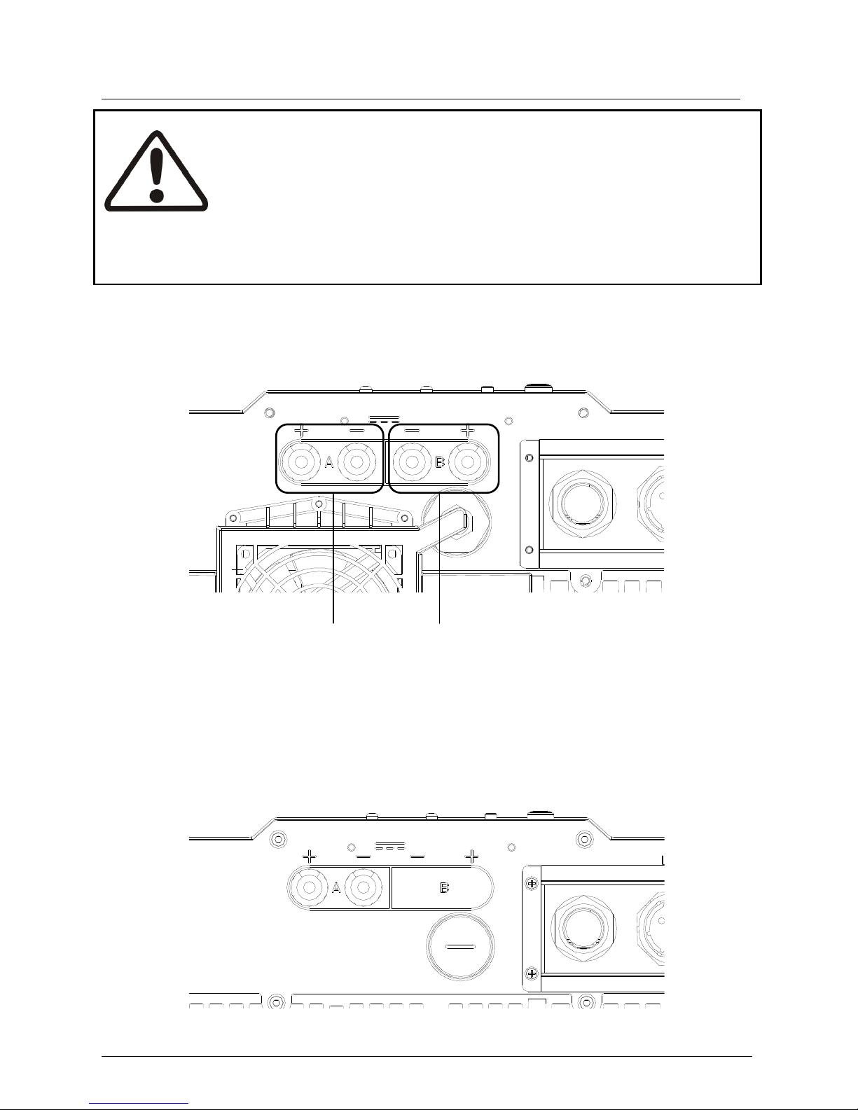
5.3.2 Connection to the PV generator (DC)
Attention!
In order to safeguard the installation and startup of the device, a
manual circuit breaker must be configured on the DC side out of the
inverter. The breaker should have certain capacity of over current and
overvoltage. In addition, before cutting off the connection of DC side, please cut off
the AC side connection first.
The PV generator strings are connected directly to the terminal in the connection box.
Two strings can be connected to the Eversol TL4600 and TL5400
A+and A-B
+and B-
Please connect A+and A-, B+and B-. Like A+and B-, B+and A-is wrong, which will
cause the inverter out of work, for A and B, they work under different conditions.
Only one string can be connected to the Eversol TL2100 and TL3200
This manual suits for next models
3
Table of contents
Popular Inverter manuals by other brands

SOLINTEG
SOLINTEG MHS-3K-30 user manual

Western Co
Western Co Leonardo Off-Grid 8kW-8000-48 MG user manual

Steca
Steca coolcept StecaGrid 1500 Installation and operating instruction

Voltec
Voltec TARKA 126 VSBD Installation and maintenance manual

Midian Electronics
Midian Electronics MOT-TVS-2-PRO instructions

PROLiNK
PROLiNK IPS Series user manual

AirMan
AirMan SG Series instruction manual

Siemens
Siemens MICROMASTER 411 operating instructions

Champion
Champion ParaLink 100468 Operator's manual

Huawei
Huawei SUN2000-175KTL-H0 quick guide

Samlexpower
Samlexpower PST-12S-12A owner's manual

Analytic Systems
Analytic Systems IPS600 SERIES Installation & operation manual


