PROLiNK IPS Series User manual

OFF-GRID SOLAR INVERTER
User Manual
IPS SERIES – TOWER/DESKTOP/WALL MOUNT
IPS3003-P/M & IPS5003-P/M
3KVA/5KVA
Version 1.00
(English)

1
Table of Contents
SAFETY INSTRUCTIONS ............................................................................................................... 2
PRODUCT OVERVIEW ................................................................................................................... 3
PRODUCT OUTLOOK ..................................................................................................................... 3
INSTALLATION ................................................................................................................................ 5
OPERATION .................................................................................................................................... 8
TROUBLE SHOOTING .................................................................................................................. 16
SPECIFICATION ............................................................................................................................ 17
DIPOSAL ....................................................................................................................................... 18

2
SAFETY INSTRUCTIONS
Before using the product, please read carefully the warning messages and instructions on labels and user manual of this
product and other components connected to the product.
This product is designed to be connected with lead-acid battery only. Do not connect the product with other types of battery.
To reduce risk of damage and injury, please use batteries with good quality.
In the event flooded batteries are used, regular maintenance on the battery shall be performed.
The product is design for indoor installation. Please do not expose the product to direct sunlight, rainfall, or snow.
Before performing any maintenance on the product, please disconnect all power sources (AC mains, batteries, solar panel) to
avoid the risk of electrical shock.
Do not attempt to disassemble or repair the product. Only authorized personal are allowed to perform repair.
While performing maintenance or cleaning (especially on the batteries where hazardous liquid might be touched), it’s
recommended to wear necessary personal protections (e.g. gloves and goggle).
The product and external batteries shall not be installed anywhere near smoke, spark, and flame.
In the event a generator with auto-start function is connected with the product, before performing maintenance or cleaning
should disconnect it.

3
PRODUCT OVERVIEW
This is a DC-to-AC inverter, which can be used as a long run-time UPS (Uninterruptible Power Supply), an energy-saving solution or
an automotive inverter (hereinafter referred to as “inverter”).
The inverter accepts input power source from AC mains (utility), battery and PV (solar) string and switches between various
operation modes automatically depending on the operational conditions.
When used as an UPS, battery or PV (solar) string acts as back-up power source to supply loads during the outage of AC mains.
When used as an energy-saving device, the PV (solar) string can be set as priority to supply the loads without consuming the power
from AC mains, as long as sufficient sunlight is present.
The battery can be charged by both AC mains and PV (solar) string with intelligent charging control.
Key features:
Automatic line-to battery switchover
Built-in enhanced AC charger
Built-in solar charger controller up to 60A
Selectable input voltage ranges/charging priority setting/AC or solar power priority setting.
High efficiency DC-to-AC conversion with minimized energy loss
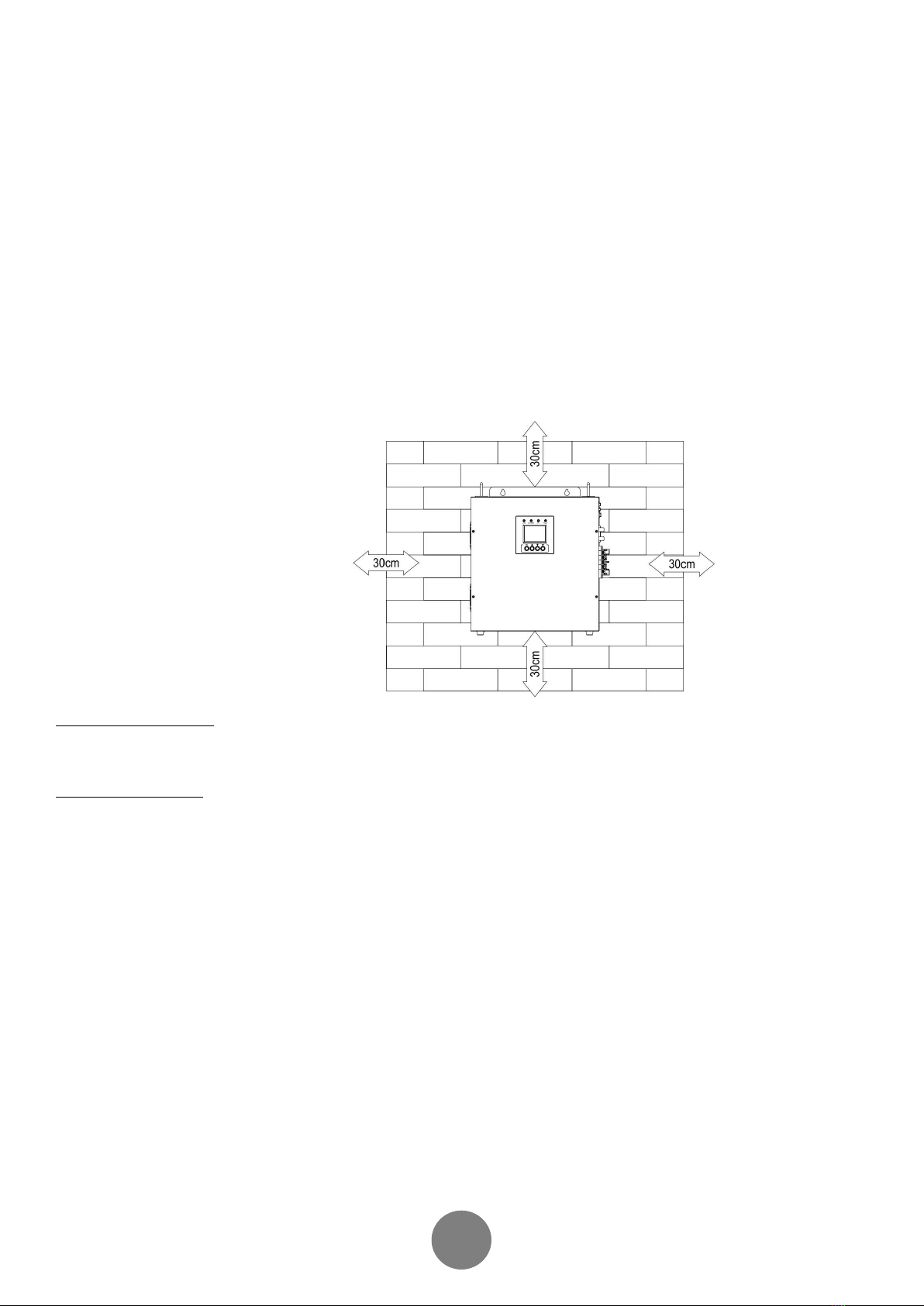
Rack design & wall-mounted design for flexible installation
Intelligent 3-stage charger control for efficient charging and preventing overcharge
Auto restart upon AC recovery
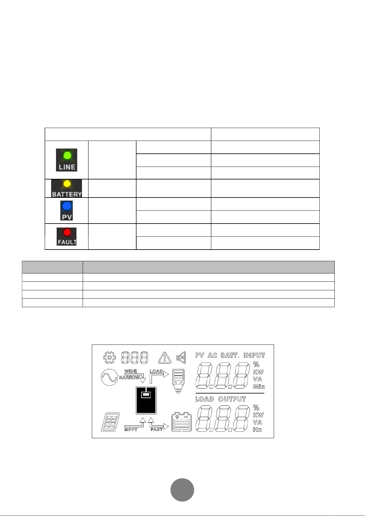
User-friendly LCD and LED indications with setting function
With the environmental temperature control charge management
Multiple protections: low battery alarm, low battery shutdown, over charger protection, overload protection, over temperature
protection, short circuit protection
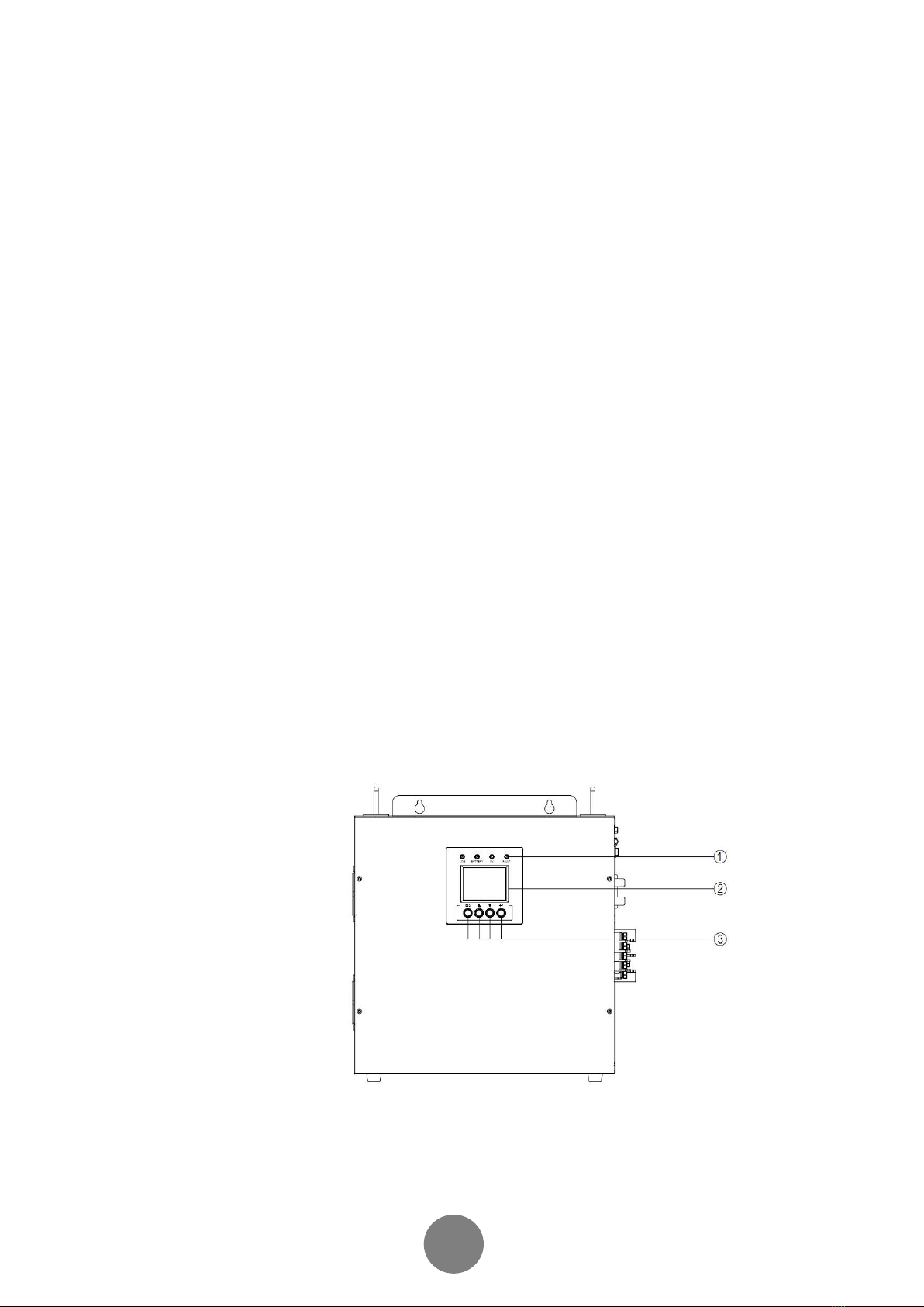
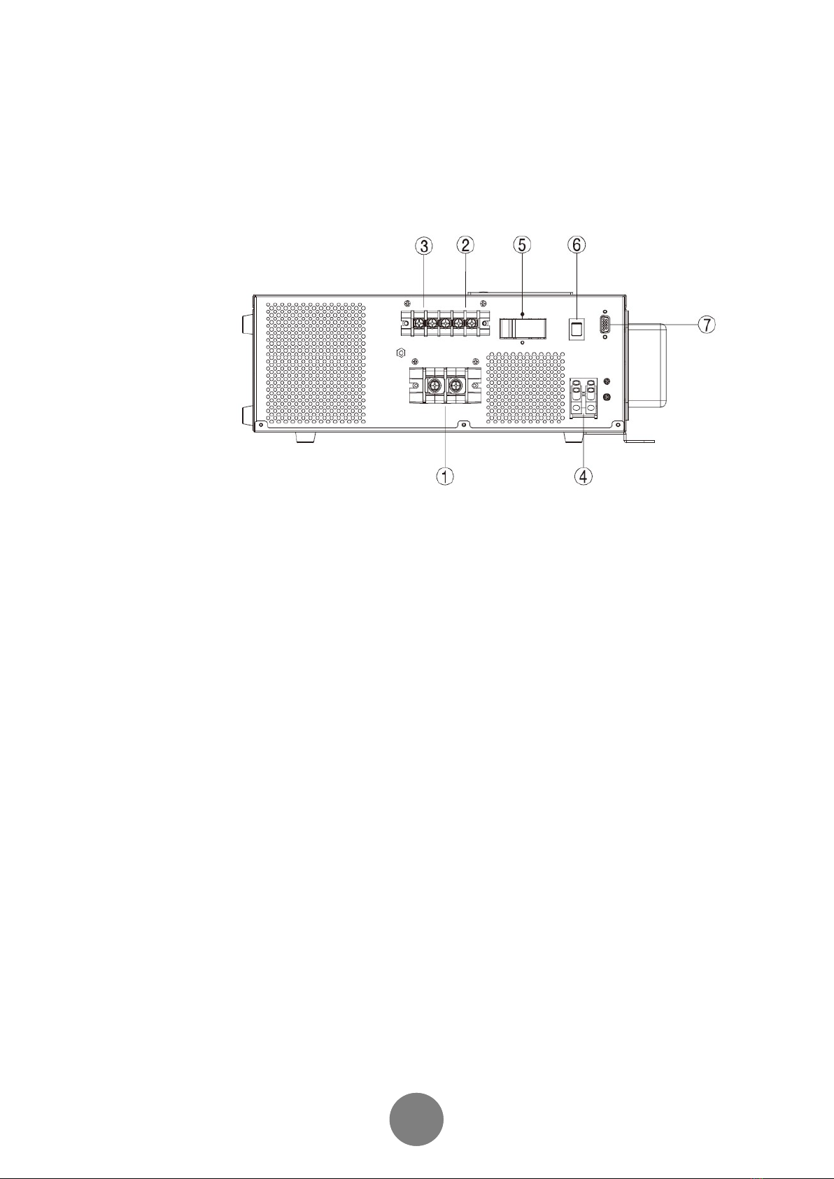
PRODUCT OUTLOOK
Top panel
1. LED indicators
2. LCD
3. Function buttons

8 4
Rear Panel
1. DC input terminals
2. AC input terminals
3. AC output terminals
4. PV input terminals
5. AC input breaker
6. Power on/off button
7. RS-232 communication port

8 5
INSTALLATION
Unpacking and Inspection
This product package include following items. Please call your supplier or dealer if any items are missing.
1 X Inverter
1 X User’s manual
2 X Setting screws
Safety Clearance
The minimum clearance to the wall shall be larger than 30cm in order to ensure proper ventilation.
In the event the ambient temperature is high, it’s recommended to increase the distance of safety clearance to improve the heat dissipation.
Mounting Inverter on the wall
The inverter is designed to either be placed on horizontal surface or be mounted on the wall with various ways (as shown below). When mounting the
inverter on the wall,
The wall shall be solid and strong enough to carry the inverter;
The location of installation shall allow the user to read the LCD easily;
Two screws shall be firstly fixed on the wall (distance as shown below) so that the inverter can be hung on the screws, recommended screw size is
M4*50~65mm.
After mounting the inverter, make sure it’s firmly mounted and won’t easily fall off in the event of unexpected earthquake or vibration.
Batteries
Determine the size of battery
The inverter is designed with pre-set charging current and voltage. Given a fixed charging current, under-sized batteries may shorten the battery life
while over-sized batteries may result in unreasonable recharging time.
It’s recommended the batteries capacity shall be no less than 200AH.
Connect the battery cables
The gauge of battery cables shall be no less than 6 AWG with 105℃ rating.
No matter how the batteries are connected (in series or in parallel), make sure the cables’ terminal voltage is consistent with the inverter’s
specification (24V for 3000VA model and 48V for 5000VA model).
It’s recommended to cover the battery terminals during the connection.
Check the polarity the cables before connecting to the inverter.
Connect the Inverter DC cables with battery terminals as shown below

8 6
While connecting multiple batteries, use the same brand/type for all batteries. Do not mix the battery bank with different brand/type of
batteries.
The user may connect the batteries in series in order to double the voltage connected to inverter. The diagram below illustrate how to connect two
12V batteries in series to make up 24V (for 3000VA model) and four 12V batteries in series to make up 48V (for 5000VA model)
PV (solar) string
Selection of PV Panel
PV string is a connection of PV panels whose output voltage and current vary under different illumination. And just like battery, the PV panel can be
connected in either series or parallel as per needed. Please consult the supplier or PV panel so that the operational voltage and current fall within the
allowed range of the inverter as set out in the specification.
Please do not use PV panel which requires one terminal connected to ground (e.g. thin-film panel)

8 7
Connect the PV strings
As the PV string generates power as long as illumination exists, a circuit breaker shall be installed between the PV string and inverter so that
the power from PV string can be switched off when needed (e.g. regular maintenance)
Connect the cables from PV string to PV input terminals as shown below. Please check the polarity before connection.
Connect to Utility and charge Connect AC input Cables and loads
Connect the AC input cables and loads to the receptacles as shown below.
Plug in the AC input power cord to the wall outlet. The unit will automatically charge the connected external battery even though the unit is off.
AC input voltage range selector
“NARROW “setting:
Configure LCD to “NARROW” when connected with loads which are more sensitive on voltage range. With this setting, the inverter is more sensitive
to the voltage disturbance on the AC input and input voltage range is set at 170~280VAC while output voltage follows input voltage.
“WIDE “setting:
Configure LCD to “WIDE” when connected with loads which are less sensitive on voltage range (e. g. light bulb, fan, fluorescent tube, or TV). With
this setting, the input voltage range is set at 90~280VAC while output voltage follows input voltage.
Please note that the inverter’s transfer time switching from Line Mode to Backup Mode gets longer as the input voltage gets low. Under the
circumstance, connecting the inverter with loads which are sensitive to transfer time (e.g. computer) might result in power interruption.

8 8
OPERATION
After connecting batteries, AC input cables, and loads, the inverter is now ready to work.
Power on/off
Once the inverter has been properly installed, press the power switch to turn on the unit. The unit will work automatically in line mode or inverter
mode according to input utility power’s status. When press the power switch again, the unit will be turned off.
LED Indicators
The operation mode of the inverter can be easily understood by LED indicators. Please see the table below for details.
LED indicators Information
GREEN
Line mode 1
(Battery is empty) Green flashing every 2 seconds
Line mode 1
(Battery is full) Green solid lighting
Off-charge mode with AC Green flashing as cycle:
0.5s On→0.5s Off→0.5s On→3.5s Off
YELLOW Battery mode
Bat low
Yellow solid lighting
Flashing every 2 second
BLUE
PV mode Blue solid lighting
Off-charge mode with PV Blue flashing as cycle:
0.5s On→0.5s Off→0.5s On→3.5s Off
RED
Overload Red flashing every 0.5 second
Fault Red lighting
Function Keys
Function key Description
ESC To exit setting mode
UP To go to previous selection
DOWN To go to next selection
ENTER To confirm the selection in setting mode or enter setting mode
LCD Display
LCD displays the power flow and input/output readings in a visualized graphic design which allows the user to understand the operation status easily.
The backlight of LCD remains on whenever the inverter is working (including Standby Charging Mode and Fault Mode).

8 9
Icon Function
Input source information
Indicates utility power
Indicates the PV power
Configuration Program and Fault Information
Indicates the setting programs
Indicates the warning and fault codes
Indicates mute
Indicates standby mode
Indicates power on mode
Other Information
Indicates input, output, PV and battery information
Battery Level
Indicates battery level in battery mode and charging status.
Load level
Indicates the load level.
LCD Setting
When the power switch is turned on, pressing and holding “ENTER” button immediately for 3 seconds, the unit will into
the setting mode. Press “UP” or “DOWN” button to select setting programs. And then, press “ENTER” button to
confirm the selection or “ESC” button to exit. The unit will exit setting mode if no operating for 30s.

8 10
Function
LCD Display
Options
Default
Description
Buzzer enable
ON
OFF
ESC
Buzzer on Buzzer is enable default, you can set it
disable to turn off alarm sounding.
AC input voltage
range
Hi(wide)
Lo(narrow)
ESC
Hi
If select Hi, AC input voltage will be within
90-280VAC.
If select Lo, AC input voltage will be within
170-280VAC.
AC output
voltage select
220V
230V
ESC
230V
Output Source
Priority
SOL
UTI
SBU
ESC
SOL
If setting “Utility” priority, utility will provide
power to loads as first priority. Solar and
battery energy will provide power to loads
only when utility power is not
available.(default)
If setting “SOL” priority, solar energy will
provide power to loads as first priority. If
solar energy is not sufficient to power all
connected loads, battery energy will
supply power to the loads at the same
time.
Utility provides power to the loads only
when any one condition happens:
-Solar energy is not available
-Battery voltage drops to the low-level
warning voltage or the setting voltage
point in program 006
If setting “SBU priority”, solar provides
power to the loads as first priority.
If solar energy is not sufficient to power all
connected loads, battery energy will
provide power to the loads at the same
time. Utility provides power to the loads
only when battery voltage drops to either
low-level warning voltage or the setting
point.

8 11
Charger Source
priority
All
UTI
PV
OSO
ESC
All
If setting “Both”, the solar power
and utility power charging the
battery together.(default)
If setting “Utility”, the utility
power charging the battery first.
Solar energy will charge battery
only when utility power is not
available.
If setting “PV”, the solar power
charging the battery first. Utility
energy will charge battery only
when solar power is not
available.
If setting ”OSO”, only solar
power charging the battery no
matter utility is available or not.
Setting DC
voltage point
back to utility
when selecting PV
priority
Note: This setting
voltage cannot be
higher than that in
P07 program
Available options in
3000VA model :
22.0/22.5/23.0/23.5
/24.0/24.5/25.0/25.5V .
ESC
Available options in
5000VA
model :44.0/45/46/47/
48/49
/50/51V .ESC
23V for
3000VA
46V for
5000VA
Unit works in PV mode, if solar
power is not sufficient to supply
loads, the battery will power
loads at the same time. When
battery voltage drops to the
setting voltage point, unit will
transfer to utility mode.
Setting voltage
point back to
battery mode
when selecting
“SBU” or “SOLAR
FIRST”
Note: This setting
voltage cannot be
lower than that in
P06 program
Available options in
3000VA model :
FUL/24.0/24.5/25.0/25
.5/26.0/
26.5/27.0V/ESC
Available options in
5000VA model :
FUL/48.0/49.0/50.0/51
.0/52.0/
53.0/54.0V/
ESC
27.0V
for
3000VA
54.0V
for
5000VA
When selecting “SOL” priority
for load, if solar power is not
sufficient to supply loads, and
battery voltage drops to the
setting voltage point in P06, unit
will transfer to utility mode.
When battery voltage is
charging up to the setting
voltage point in 006, unit will
transfer back to PV mode.

8 12
Max charging
current: To
configure total
charging current
for solar and utility
chargers:(Max
charging
current=utility
charging current +
solar charging
current)
10/20/30/40/50/60/70/
80/90 /100A
ESC
NA
Max. charging current=utility
charging current + solar
charging current
Maximum AC
charging current
10/20/30/40A
ESC NA
If setting value in 008 is smaller
than that in 009, the inverter will
apply charging current from 008
for utility charger.
Auto restart
voltage
For 24V model:
Any/21.0/22.0/23.0/24.
0/25.0 /26.0/FUL .ESC
For 48V model:
Any/42.0/44.0/46.0/48.
0/50.0
/52.0/FUL .ESC
Any
Utility power come back after
inverter shut down at battery low
condition, the inverter will auto
restart if battery voltage is
charging up to setting point.
Battery shutdown
voltage setting
Available options in
3000VA model :
20.0/20.4/20.8/21.2/
21.6/22.0V .ESC
Available options in
5000VA model :
40.0/40.8/41.6/42.4/
43.2/44.0V .ESC
21.2V
for
3000VA
42.4V
for
5000VA
Setting range is from
20.0V to 22.0V for 24V model
and 40.0V to 44.0V for 48V
model. Low cut-off voltage will
be fixed to setting value no
matter what percentage of load
is connected.
Battery model
Energy-Saving
setting
No
Yes No
User can set Energy-Saving
model in this program to reduce
the consumption in battery
mode.
Initialize
No
Yes No If necessary, user can restore
factory settings in this program.

8 13
Operating Mode Description
Operating mode LCD Display
Standby charging mode
Battery can be charged without
switching on the unit.
Utility input bypass to output, and charge the battery.
Battery is charging by PV energy only, no AC output.
Utility input bypass to output, and charging by both utility and PV.

8 14
Line mode Utility input bypass to output, and battery can be charged when
switching on the unit.
Utility input bypass to output, and battery can be charged by both
utility and PV when switching on the unit.
Battery mode The backup power to load comes only from battery.
The backup power to load comes from battery and PV energy.

8 15
Fault and warning code
Fault Code Event Audible Alarm
A64 Overload Rapid beeping every 1/2 second
A68 High Temperature Beep every second
A88 PV Voltage High Beep every second
A89 PV Current High Beep every second
A91 PV Charger NTC Disconnect Beep every second
E07 Output Voltage High Constant tone
E09 Output Short Constant tone
E14 Overload Fault Constant tone
E18 Fan Fail Constant tone
E13 Over Charge Constant tone
E25 Output Voltage Unbalance Constant tone

8 16
TROUBLE SHOOTING
Problem
Possible Cause
Remedial Action
No LCD display
Battery voltage is low Re-charge the battery and check if the
battery cables are well-connected
Battery is defective Replace the batteries
Power button is not pressed Press and hold the power button
Mains are normal but works in backup
mode AC input is absent Check the connection of AC input
Backup time is short
Overloading Disconnect non-critical loads
Battery voltage is too low Re-charge battery for at least 8 hours
Battery is bad Replace good quality batteries
Alarm buzzer beeps continuously Inverter entered into fault mode
Refer to the fault code to identify the fault
and report to service representative for
further assistance
Solar are normal but Solar charger
doesn’t work
PV reverse polarity protection Re-connect the PV terminals
Some parts wrong Refer the fault and warning code

17
SPECIFICATION
Model 3K 5K
CAPACITY VA/W 3000VA/2400W 5000VA/4000W
NOMINAL BATTERY VOLTAGE 24Vdc 48Vdc
LINE MODE
INPUT Nominal Voltage 220/230/240Vac
Voltage Range Wide mode: 90VAC-280VAC(default)
Narrow mode: 170VAC-280VAC
Normal Frequency 50/60Hz
OUTPUT Voltage 220/230/240Vac
Frequency Follow the Utility
Output Waveform Follow the Utility
EFFICIENCY >96%(full R load, battery full charged)
TRANSFER TIME Wide mode: 40ms max, Narrow mode: 8ms max
BATTERY MODE
OUTPUT Voltage 220/230/240Vac
Frequency 50/60Hz(Auto detection)
Output Waveform Pure sine-wave
EFFICIENCY >80%
OVERLOAD PROTECTION 1min@ >110%,0s@>120%
PROTECTION Discharge, over-charged, over-load, short-circuit protection
BATTERY CHARGER(powered by AC)
CHARGING ALGORITHM 3-stage charging
AC CHARGE CURRENT 10/20/30/40A (selectable)
FLOATING CHARGING VOLTAGE 27V 54V
OVER CHARGING VOLTAGE 32V 64V
MPPT SOLAR CHARGER
Solar power to support load 1600W 3200W
CHARGING CURRENT 60A Max.
NOMINAL BATTERY VOLTAGE 24V 48V
MPPT operating voltage range 30~80V 60~150V
Max. PV Array Open Circuit Voltage 80V 150V
MAX. PV INPUT CURRENT 50A
PWM SOLAR CHARGER
Solar power to support load 1350W 2700W
CHARGING CURRENT 60A Max.
NOMINAL BATTERY VOLTAGE 24V 48V
PWM operating voltage range 30-36V 60-72V
Max. PV Array Open Circuit Voltage 60V 90V
MAX. PV INPUT CURRENT 60A
Physical
Total # of INVERTER Receptacles (1) Terminal Block
Maximum Dimensions 378mm(W)*263mm(H) *140mm(D)
Weight 30kg 30.3kg
Warning Diagnostics
Indicators INVERTER Status Display,
Audible Alarms Low Battery, Overload, Fault
Environmental
Operating Temperature 0C to 50C
Operating Relative Humidity 0 to 90% NON-CONDENSING
Management
Auto-Charger Yes
Auto-Restart Yes

18
DIPOSAL
In the event the product reaches the end of its service life, please contact the local dealer for disposal
instructions.
The product must not be disposed of with the household waste.
Disposal of the product at the end of its service life shall be done in accordance with applicable regulations
for electronic waste.

Register Online For Your Product Warranty @ www.prolink2u.com/register
PROLiNK® is a trademark of FIDA INTERNATIONAL (S) PTE LTD and is manufactured under its authority. All other
brands, products, services, logos and company names mentioned herein are trademarks of their respective owners.
All specifications, designs and contents are subject to changes without prior notice. © Copyright 2019. PROLiNK®
all rights reserved.
WORLDWIDE CUSTOMER CARE CENTERS
INDONESIA Office
PT PROLiNK INTIDATA NUSANTARA
Walk-In : Jl. Cideng Barat No. 79, Jakarta Pusat 10150, Indonesia.
Email Support : support.id@prolink2u.com
MALAYSIA Office
FIDA SYSTEMS (M) SDN BHD
Walk-In : 29 Jalan USJ 1/31, 47600 Subang Jaya, Selangor Darul Ehsan, Malaysia.
Email Support : support.my@prolink2u.com
SINGAPORE Office
FIDA INTERNATIONAL (S) PTE LTD
Walk-In : Block 16 Kallang Place #06-02, Kallang Basin Industrial Estate, Singapore 339156.
Email Support : suppor[email protected]
Technical Support Hotline
INDONESIA : +62 21 3483 1717
MALAYSIA : +60 3 8023 9151
SINGAPORE : +65 6357 0666
Note: Closed on Saturdays, Sundays and local/regional Public Holidays.
This manual suits for next models
6
Table of contents
Other PROLiNK Inverter manuals
Popular Inverter manuals by other brands

ECO-WORTHY
ECO-WORTHY ECO3000W user manual

socomec
socomec SUNSYS P33TR Installation and operating manual

Mitsubishi Electric
Mitsubishi Electric FREQROL-K Series instruction manual

Daikin
Daikin 3MKD75BVMA8 Service manual

Agilent Technologies
Agilent Technologies 33120A quick guide

Omron
Omron 3G3MX2-AB001-V1 instruction manual