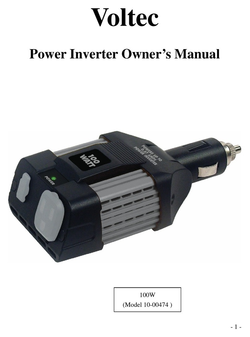
Voltec TARKA 126 VSBD Manual

1 2020installation _Manuel and maintenance TARKA 120 VSBD_VSMD_v1.0
Installation and maintenance manual for photovoltaic
modules
TARKA 126 - 138 in VSBD or VSMD
I. INTRODUCTION......................................................................................................................... 2
II. GENERAL SAFETY INSTRUCTIONS .............................................................................................. 2
2.1) FIRE SAFETY.................................................................................................................................. 2
2.2) PRECAUTIONS INSTALLATION ...................................................................................................... 3
2.3) PREPARATION OF THE INSTALLATION ......................................................................................... 4
2.4) STORAGE ...................................................................................................................................... 4
2.5) HANDLING.................................................................................................................................... 4
III. MECHANICAL INSTALLATION.................................................................................................... 5
3.2) CHOICE OF ASSEMBLY STRUCTURE AND INTEGRATION SYSTEM ................................................ 5
3.3) FASTENING OF TARKA 126 & 138 VSBD OR VSMD FRAME PANELS TO THE STRUCTURE.......... 5
(IV) ELECTRICAL INSTALLATION..................................................................................................... 8
4.1) GROUNDING OF PANELS.............................................................................................................. 8
4.2) CONNECTION MODULES TOGETHER............................................................................................ 9
4.3) CONNECTION OF MODULE CHAINS ............................................................................................ 9
V. MAINTENANCE...................................................................................................................... 10

2 2020installation _Manuel and maintenance TARKA 120 VSBD_VSMD_v1.0
I. INTRODUCTION
The installation and maintenance manual contain in formation on the handling and installation of
VOLTEC Solar's photovoltaic modules. All instructions must be read and understood before proceeding
with the installation. If you have any questions, please contact VOLTEC Solar. The installer must comply
with the safety instructions listed in the manual when installing the modules. Before installing a solar
photovoltaic system, the installer must familiarize himself with the mechanical and electrical
requirements of photovoltaic systems in general. Keep this manual in a safe and accessible place so
that you can consult it later.
In the rest of the text, unless specified, the terms: "module", "PV module" and "panel" are used
interchangeably for the TARKA 126 & 138 VSBD and VSMD framed panels.
II. GENERAL SAFETY INSTRUCTIONS
Do not use a PV module in a situation or place where a failure could result in fatal accidents, injuries
or material damage. Ensure that pv modules conform to the specifications of the overall system
implemented.
DISCLAIMER
Failure to carry out the minimum checks and maintenance operations defined in this manual may
result in the withdrawal of all voltec solar warranties for all consequences a rising from this failure.
2.1) FIRE SAFETY
Refer to local requirements and standards for fire safety guidelines and specific requirements. A roof
installation can affect the fire safety of a building ; inadequate installation can increase the risk in the
event of a fire.
The panels shall be mounted above a fire-resistant coating. Do not use signs near equipment or places
where flammable gases can be generated or collected.

3 2020installation _Manuel and maintenance TARKA 120 VSBD_VSMD_v1.0
2.2) PRECAUTIONS INSTALLATION
Installers must be qualified, and have experience in electrical work and the installation of photovoltaic
systems.
The installation must be carried out in accordance with the documents in circulation, for example,
electrical standard NF C 15-100,guide UTE C 15-712-1 and "Practical guide for use by design offices and
installers for the installation of photovoltaic generators connected to the network" published by
ADEME and ser.
Carefully insert the modules by applying safety rules to avoid injury and property damage. Handling
precautions apply and must be scrupulously observed during the installation of modules.
Do not plug water drain holes.
Do not use a damaged PV module. A damaged module can cause a fire or electric shock with
injuriesor even death. Do not expose the PV module to artificially concentrated solar radiation. A PV
module exposed to the sun generates voltage and current. Contact with the output wiring can cause
a short circuit, fire or electric arc.
Never open electrical connections or disconnect connectors when the circuit is charging (PV in the
sun).
On site, control the unladen voltage of the modules using a multimeter; the voltage measured shall be
substantially equal to the voltage indicated on the module data sheet.
The maximum number of panels in series depends on the design of the plant, the type of inverter
chosen, the environmental conditions and the maximum working voltage of the modules (refer to the
product data sheet).
We recommend that you limit the number of modules connected in series to the maximum values
shown in the following table:
Panel reference
Maximum number of panels in series
TARKA 126 VSBD or VSMD
46
TARKA 138 VSBD or VSMD
43
Connect in parallel only modules or series of modules of the same voltage. If modules or series of
modules are connected in parallel, the total current is equal to the sum of the currents of the individual
modules or series of modules.
Do not connect PV modules or chains in parallel without a properly sized current limiting device. In
parallel configuration, be sure to use only modules of the same type.
If more than two strings are configured in parallel, then a group join box must be used. The maximum
reverse current of voltec solar modules is 30A. The junction box must therefore be equipped with a
protective device whose size is less than or equal to the specified reverse current value.
The maximum number of modules or chains in parallel per protective equipment is therefore 1.
The safety factor of 1.25 for the minimum voltage characteristics of the components can be modified
during the design of a system, depending on the minimum temperature at the installation location and
the temperature coefficient for Voc, Isc can be corrected from the maximum temperature, illuminance
and orientation of the module. For this purpose, a complete simulation of the specific environment
using long-term meteorological data is required.

4 2020installation _Manuel and maintenance TARKA 120 VSBD_VSMD_v1.0
Cables connected to VOLTEC Solar modules must have a minimum section of 4mm². VOLTEC SOLAR
photovoltaic panels are certified EN IEC 61730-1 and -2 and 61215. They meet the electrical criteria of
class A: generally accessible hazardous electrical installations (according to IEC 61730 for systems
operating at more than 120 VDC). VOLTEC SOLAR photovoltaic modules meet the requirements of
protection class II defined in NF EN 61140 and are capable of operating under environmental
conditions described according to IEC 60364-5-51.
2.3) PREPARATION OF THE INSTALLATION
For on-site assembly operations, provide all safety measures to prevent the slipping or fall of a panel,
mounting accessories or tools and thus avoid any injury or damage to persons or property.
Mark on the ground the risk area to prevent access to persons from outside the site.
Delimit the area of work, to prevent the risks related to falling objects.
Implement the appropriate safety, in accordance with the regulations in force, for workers working
atheights.
Use of appropriate equipment(sliding scale, scaffolding,etc.).
Access development allowing the movement of people without direct support on photovoltaic
modules (roofer ladders, nacelle ...).
Use of collective safety equipment(railings, net, scaffolding...) and individual (safety harness,laath,
helmet...).
2.4) STORAGE
The modules are delivered vertically on pallet with cardboard packaging and strapping. They mustbe
stored in this way. As soon as the cerclages are removed, the modules must be supported or laid
horizontally with the plastic bumpersor cardboard corners as separators.
Attention: pallets must be stored on flat ground protected from the elements.
2.5) HANDLING
Handle the photovoltaic module with care. Wear clean and soft gloves to avoid direct hand contact
with the glass. When using suction cups or handling straps, ensure that they are clean and free of any
fat or abrasive. Prohibit any contact of the glass with a fatty substance or containing silicone. Do not
put or drop any object whatsoever on the glass.
Do not unmount the module. Do not modify or delete any component. Do not exert pressure on the
PV module leading to bending of the surface. This could cause micro crassures of the cells.
Do not stand or walk on a module: risk of breaking cells (microcracks) or damaging the surface of
the glass (scratches, fouling).
Do not hit the front or back of the PV module with a hard or sharp object.
Do not knock or drop the PV module. Do not touch components that can be powered on: wires,
cables, connectors, or junction boxes.
Ensure that the intended shut-off device, disconnector or circuit breaker, is opened before any
intervention.
Always use appropriate safety equipment (insulated tools, insulating gloves, insulating shoes, etc.)
Do not use cables or connectors as a means of handling.

5 2020installation _Manuel and maintenance TARKA 120 VSBD_VSMD_v1.0
III. MECHANICAL INSTALLATION
3.1) CHOICE OF LOCATION
Choose an appropriate location for installing the modules.
The maximum allowable load applies to the uniformly distributed load of wind or snow. Avoid installing
signs in areas exposed to gusts of wind, snow, ice cubes or ice build-up. The maximum altitude of use
of modules of all ranges is 800 meter.
3.2) CHOICE OF ASSEMBLY STRUCTURE AND INTEGRATION SYSTEM
Load and strength calculations are the responsibilityof the project owner or installer.
Ensure that panels are not subjected to wind or snow loads in excess of the maximum allowable loads
and are not subjected to excessive forces due to the thermal expansion of the support structure.
The mounting structure that will receive the panels must be able to withstand the forces created by
the panels, the wind, the snow. These efforts vary according to geographical location. The mounting
structure and fastening material must be made of durable materials that are resistant to corrosion and
UV.
Read the local settings before making the choice.
For roof-mounted systems, provide adequate rear ventilation under the panel to ensure good cooling
(> 5 cm). The panels must be securely fixed using support frames or mounting accessories specially
designed for PV applications. Always keep the rear surface of the panel free of any foreign objects or
structural elements that may come into contact with the panel, especially when the panel is subjected
to a mechanical load.
3.3) FASTENING OF TARKA 126 & 138 VSBD OR VSMD FRAME PANELS TO THE STRUCTURE
Comply with all safety instructions and precautions for the implementation of the integration system.
The modules shall be securely attached to the mounting structure using a minimum of four attachment
points for normal installation. If high winds or snow loads are foreseeable, provide additional
attachment points. Refer to the recommendations of the supplier of the assembly system.

6 2020installation _Manuel and maintenance TARKA 120 VSBD_VSMD_v1.0
Fixing diagram of TARKA 126 & 138 VSBD or VSMD panels:
*Loads of 2400 Pa (Snow and Wind) are given according to IEC conditions.
Charge 2400 Pa * Charge 5400 Pa *
Fixation par l'arrière des panneaux
Attache sur le retour du long cadre par
clipsage
Fixation par étriers
Attache sur la longueur du cadre
Fixation par étriers **
Attache sur la largeur du cadre

7 2020installation _Manuel and maintenance TARKA 120 VSBD_VSMD_v1.0
Module dimensions:
Glass
thickness
Module
dimensions (mm)
Junction box
(mm)
Dimensions of the Alu frame profile (mm)
Long.
cable
(mm)
model
-
Long.
wide.
Long.
wide.
Return of the frame
Long Side /Small Side
-
WISE 126
VSBD to
VSMD
3.2mm /
4.0mm
1835
1042
100
30
25 / 14,5
1200
Yes
1500
WISE 138
VSBD to
VSMD
3.2mm /
4.0mm
2005
1042
100
30
25 / 14,5
1200
Yes
1500
Mounting with flanges or calipers or pliers:
Respect the locations of the flanges indicated in the diagram belowus. Therefore, depending on the
portrait or landscape orientation of the modules, the mounting structure will have to have profiles
supporting the modules in the vertical or horizontal direction.
The flanges and fixing screws must be of cross-section and length in relation to the forces to be
supported (winds, snow) depending on the location.
Example of mounting with calipers:
NOTE: When mounting, the contact surface of the clamps with the panel frame shall be at least 70 per
cent. The clamping torque specified by the supplier of the fastening system shall be respected.
In case of non-compliance with this condition, no claim will be accepted and the product will no longer
be under warranty.

8 2020installation _Manuel and maintenance TARKA 120 VSBD_VSMD_v1.0
(IV) ELECTRICAL INSTALLATION
Only authorized and trained personnel should have access to PV modules. The system generates
electricity, and can be dangerous if the staff is not familiar with these products and with the
appropriate safety procedures.
The installation must be carried out in accordance with the electrical standard documents NF C 15-
100, guide UTE C 15-712-1 and "Practical guide for use by design offices and installers for the
installation of photovoltaic generators connected to the electricity grid " published by ADEME and ser.
Provide in the circuit a circuit breaker or equipment to detect leakage currents.
Do not use PV modules of different electrical characteristics and properties in the same system.
Connect in series only modules of the same nominal output current.
If the modules are connected in series, the total voltage is equal to the sum of the voltages of each
module. The open circuit voltage exceeds the nominal voltage. The solar cable used must have: a
minimum section of 4mm², a maximum permissible voltage of 1500 Vdc. The temperature of use of it
must be between -40 °C and +80 °C.
Ensure that the open circuit voltage of a module at the lowest temperature of the site multiplied by
the number of modules in series is not higher than the maximum voltage of the intended system and
all DC electrical components (DC protection and inverter in particular). Under normal conditions
(temperature, sunshine), a photovoltaic panel is likely to produce more current and/or voltage than
under standard test conditions. Consequently, the values of Isc and Voc indicated on the back of the
panel shall be multiplied by a factor of 1.25 for the determination of the sizes of the components,
sections of cables, sizes of fuse, calibration of the cut-off components and protection connected to the
exit of the panels.
Tables of characteristics: see the technical data sheets produced
Tolerances to be considered on electrical characteristics: ± 3% on Voc and ± 3% on Isc
4.1) GROUNDING OF PANELS
The frames of the modules must be grounded using the grounding holes of diameter 4 mm present on
the frame (large side) and yellow green cables of section 10 mm2with lugs or ground braids.
In order to ensure an optimal level of safety, the installation's terrestrial connection diagram must be
of type TT (neutral of the transformer connected to the ground, all masses are connected to the
ground).
Comply with all applicable local requirements and regulations.
Use approved accessories and components for electrical connections: washers with ressort or fan
(notched),bimetallic or stainless steel washers, screws, stainless steel lug - if necessary- to avoid
galvanic corrosion. Ensure good electrical continuity between the frames of the modules and between
frames and mounting structure.
Connect the entire metal structure to the earth after verification of its conformity.
During a maintenance operation that requires the disassembly of a module, ensure the ground
continuity of the installation.
Specific parts for grounding can advantageously replace cables or braids, saving time in
implementation and providing a very good contact such as Terragrif claws, patented and approved by
mobasolar. The compatibility of the terragrif chosen with the profile of the module frames must be
validated by VOLTEC Solar.

9 2020installation _Manuel and maintenance TARKA 120 VSBD_VSMD_v1.0
4.2) CONNECTION MODULES TOGETHER
Do not cut or damage cables coming out of the junction box.
The PV module has a pair of waterproof male and female connectors. For a serial electrical connection,
connect the positive connector of the first PV module to the negative connector of the next module.
Ensure that the cables do not exert tension on the junction box of the PV module.
Connect the panels to each other by means of the connectors with which they are equipped. Do not
replace them. The replacement may result in the nullity of the warranty.
At each connection between panels, ensure that the connectors are fully engaged and locked.
Improper contact can cause an electric arc or a warm-upresultingin a short circuit that can lead to a
fire.
4.3) CONNECTION OF MODULE CHAINS
Connect the output cable to other equipment in the system using a connector of the same type and
making sure to use a well-sized section cable.
Connect the required number of photovoltaic modules corresponding to the voltage and current
specifications of the equipment of the photovoltaic system(DC protection, inverter...).
Attach the cables to the mounting chassis using approved fasteners.
Connectors should be placed behind the mounting frame so that they are not directly exposed to
sunlight, wind and rain.
To extend the connecting cables and make the connections to electrical equipment, use solar cables
and quality connectors that are specifically designed for use in UV exposure and for long periods of
time. Set the appropriate cable section based on current intensity and cable length to avoid voltage
drops.
A cross-connection or "leapfrog" of photovoltaic modules is allowed.
When the wiring of photovoltaic modules is carried out after they are attached to the mounting
brackets, the non-coupled connectors must be protected from moisture and dirt by means of a sealing
cap.
For more information consult the UTE guide "Guide for cables used in photovoltaic systems", UTE 32-
502 (Nov. 2008).

10 2020installation _Manuel and maintenance TARKA 120 VSBD_VSMD_v1.0
V. MAINTENANCE
Before any intervention, make sure that the direct current electrical circuit is open (circuit breaker or
DC disconnector open).
Do not touch the energized parts, cables, connectors and junction boxes.
Always use appropriate safety equipment (insulated tools, insulating gloves, etc.)
In case of intervention or repair on the DC part, cover the front of the module with an opaque fabric
or any other material to prevent the module from producing electricity.
VOLTEC Solar recommends the following maintenance operations to ensure optimal module
performance:
Active surface of modules: glass
•Clean the glass surface of the modules as needed.
Depending on the geographical location of the installation, the presence of vegetation,
sources of dust, air pollution or any other type of dirt can be detected. Thus a cleaning
may be necessary. The examination of the signs and the possible finding of fouling will
dictate the action to be taken. To clean the glazed surface use demineralized water,
possibly mixed with a maximum of 20% of conventional windshield washer product or
alcohol, and a sponge or a soft cloth.
•Do not use dishwasher detergent. Do not exceed the proportion of 20% windshield washer
product or alcohol.
•Do not use brushes or any other abrasive or sharp equipment
Fastening structures and electrical connections
•Check if the nuts and bolts of the mounting structure are not loosen. Tighten all fasteners
that require it.
•Electrical and mechanical connections must be checked periodically by qualified personnel
to ensure that they are clean, tight or connected and in good condition.
•Check connection connections for connecting cables, ground cables and connectors.
•During a maintenance operation that requires the disassembly of a module, ensure the
ground continuity of the installation.
•Check the state of electrical and mechanical connections from the point of view of
corrosion.
•Check the mass resistance of metal parts such as the module frame and the mounting
structure.

11 2020installation _Manuel and maintenance TARKA 120 VSBD_VSMD_v1.0
VI. RECYCLING
VOLTEC SOLAR is a partner of the PV Cycle organization and contributes to the
establishment of a recycling sector.
This is why any defective or end-of-life product can be brought to one of the
many PVCYCLE collection points. Cf: www.pvcycle.org
For private households
Disposal information for WEEE users. This symbol(Figure 1) on the product and/or
accompanying documents means that used electrical and electronic equipment(WEEE) must
not be mixed with house hold waste for treatment, recovery and recycling, please bring this
product(s) to designated collection points, where it will be admitted free of charge.
Alternatively, in some countries,you mightbeable to return your products to your local reseller
when purchasing an equivalent product.
The proper disposal of this product will help to safeguard valuable resources and prevent all
potential negative effects on human health and the environment; otherwise, improper
handling of these products could increase these risks. Please contact the local authorities for
more details regarding the nearest collection point. Penalties may be imposed in the event of
incorrect disposal of such waste, in accordance with national legislation.
For professional users in theEuropean Union:
If you wish to dispose of electrical and electronic equipment(EEE), please contact your
dealer or supplier for more information.
For disposal in countries outside the European Union:
This symbol is only valid in the European Union(EU).
If you wish to dispose of this product, please contact the local authorities or your reseller to
find out the appropriate method of treatment.
VOLTEC Solar SAS
R.C.S. Saverne B 518 706 965
N°TVA FR56518706965
1, rue des Prés
67190 Dinsheim-sur-Bruche
France
www.voltec-solar.com
Disposal instructions: Please dispose of used electrical and electronic equipment
(WEEE) at designated collection points for recycling such equipment
FIGURE 1
This manual suits for next models
3
Table of contents
Other Voltec Inverter manuals