EVERWATCH 8620 User manual

Model 8620
EVERWATCH
Room
Pressure
Monitor
User's Guide

Model 8620
EVERWATCH
Room
Pressure
Monitor
User's Guide
July 1994
P/N 1980105
Rev. B
U.S. AND CANADA OTHER COUNTRIES
Sales & Customer Service: Sales & Customer Service:
(800) 777-8356/(651) 490-2711 (001 651) 490-2711
Fax: Fax:
(651) 490-2874 (001 651) 490-2874
SHIP TO: MAIL TO:
TSI Incorporated TSI Incorporated
ATTN: Customer Service P.O. Box 64394
500 Cardigan Road St. Paul, MN 55164
Shoreview, MN 55126 USA
USA
E-MAIL
WEB SITE
www.tsi.com

Copyright TSI Incorporated/July 1994/All rights reserved.
Part number1980105 Rev. B
LIMITATION OF WARRANTY AND LIABILITY
Seller warrants that this product, under normal use and service as described in the operator's manual, shall
be free from defects in workmanship and material for a period of twenty-four (24) months, or the length of
time specified in operator's manual, from the date of shipment to the customer. This limited warranty is
subject to the following exclusions:
1. Batteries, hot wire or hot film sensors and certain other components when indicated in
specifications are warranted for a period of 90 days from the date of shipment to the customer.
2. With respect to any repair services rendered, seller warrants that the parts repaired or replaced will
be free from defects in workmanship and material, under normal use, for a period of 90 days from
the date of shipment to the customer.
3. Seller does not provide any warranty on finished goods manufactured by others. Only the original
manufacturer's warranty applies.
4. Unless specifically authorized in a separate writing by seller, seller makes no warranty with
respect to, and shall have no liability in connection with, any goods which are incorporated into
other products or equipment by the Buyer.
The foregoing is IN LIEU OF all other warranties and is subject to the conditions and LIMITATIONS
stated herein. NO OTHER EXPRESS OR IMPLIED WARRANTY OF FITNESS FOR
PARTICULAR PURPOSE OR MERCHANTABILITY IS MADE.
THE EXCLUSIVE REMEDY OF THE USER OR PURCHASER, AND THE LIMIT OF THE
LIABILITY OF SELLER FOR ANY AND ALL LOSSES, INJURIES, OR DAMAGES IN
CONNECTION WITH THIS PRODUCT (INCLUDING CLAIMS BASED ON CONTRACT,
NEGLIGENCE, STRICT LIABILITY, OTHER TORT, OR OTHERWISE) SHALL BE THE
RETURN OF THE PRODUCT TO THE FACTORY OR DESIGNATED LOCATION AND THE
REFUND OF THE PURCHASE PRICE, OR, AT THE OPTION OF SELLER, THE REPAIR OR
REPLACEMENT OF THE PRODUCT. IN NO EVENT SHALL SELLER BE LIABLE FOR ANY
SPECIAL INCIDENTAL OR CONSEQUENTIAL DAMAGES. NO ACTION, REGARDLESS OF
FORM, MAY BE BROUGHT AGAINST THE SELLER MORE THAN ONE YEAR AFTER THE
CAUSE OF ACTION HAS ACCRUED.
The purchaser and all users are deemed to have accepted the terms of this LIMITATION OF
WARRANTY AND LIABILITY, which contains the complete and exclusive limited warranty of seller.
This LIMITATION OF WARRANTY AND LIABILITY may not be amended or modified nor may any of
its terms be waived except by a writing signed by an authorized representative of seller.
SERVICE POLICY
Knowing that inoperative or defective instruments are as detrimental to TSI as they are to our customers,
our service policy is designed to give prompt attention to any problems. If any malfunction is discovered,
please contact your nearest sales office or representative, or call TSI's Customer Service department at
(800) 777-8356.


i
CONTENTS
Introduction 1
Chapters 1 Getting Started 3
Configuration 3
Calibration 3
2 Operation 5
Front Panel Display 6
Front Panel Controls 7
3 Configuration 9
Description of Configuration Menu Functions 11
Configuration Procedure 14
4 Calibration 19
Calibration Procedure 20
5 Maintenance 23
Velocity Sensor Cleaning 23
Replacement Parts 23
6 Troubleshooting 25
Appendix A Specifications 27
B Theory of Operation 29
C Typical Wiring Diagram 35
D Configuration Menu Flow Chart 37
Figures 1. EVERWATCH Front Panel Display and Controls 5
2. EVERWATCH Bridge Circuit 30
3. EVERWATCH Wiring Diagram 35
Tables 1. EVERWATCH Configuration worksheet 9
2. Troubleshooting 25
3. Display Averaging Period Example 31

ii
CONTENTS

1
INTRODUCTION
The EVERWATCH User's Guide describes how to operate, configure, calibrate,
maintain and troubleshoot the Model 8620 EVERWATCH
Room Pressure
Monitor. Please read this guide thoroughly before using the EVERWATCH.
This guide assumes that the EVERWATCH has been properly installed. Refer to
the Installation and Checkout Instructions if there is any question as to whether
the EVERWATCH has been installed properly.
The User's Guide has been divided into the following chapters to simplify its
use.
Chapter 1 describes how to program the EVERWATCH.
Chapter 2 describes how to operate the EVERWATCH.
Chapter 3 describes how to configure the EVERWATCH.
Chapter 4 describes how to calibrate the EVERWATCH.
Chapter 5 describes how to maintain the EVERWATCH.
Chapter 6 describes how to troubleshoot the EVERWATCH.
Appendix A lists the EVERWATCH specifications.
Appendix B describes the EVERWATCH theory of operation.
Appendix C describes how the EVERWATCH is wired.
Appendix D contains a flow chart of the configuration menus.
References to the EVERWATCH keypad and digital display are highlighted in this
guide as follows:
Example: Press the LOW ALARM key to display the low alarm set point.
A black four-pointed star is used throughout this guide to call attention to
important notes or comments.
Step-by-step instructions are denoted by numbered circles .
HELP!
Technical assistance and customer service:
Contact TSI Industrial Test Instruments Group at 1-800-777-8356.

2
INTRODUCTION

3
CHAPTER ONE
GETTING STARTED
Configuration The rooms and the environment in which the EVERWATCH operates vary
from facility to facility. There are a variety of ways to display and use
the information gathered by the EVERWATCH. The configuration
procedure is used to program the EVERWATCH to present the
information in the manner desired.
The EVERWATCH has the versatility required to operate in a variety of
configurations. The EVERWATCH comes from the factory configured for
typical operating requirements.
Before beginning to reconfigure the EVERWATCH, take a few minutes to
review the configuration procedures found in Chapter Three. Use the
configuration worksheet to determine how to configure the EVERWATCH
to suit your requirements.
Calibration The EVERWATCH Room Pressure Monitor is a very versatile device
which will work with a variety of rooms. The EVERWATCH is calibrated
at the factory to each sensor. It is imperative that the sensor and
monitor be kept as a matched set. Insure that the serial number on the
monitor matches the number on the sensor.
If the room configuration is unique, "such as 8 ft long tube" the system
should be calibrated to the new setup. The calibration procedure is quite
simple and can be accomplished in a matter of minutes with a little
preparation and practice.
Before beginning to calibrate the EVERWATCH, take a few minutes to
review the calibration procedures found in Chapter Four. A portable air
velocity meter and the calibration instructions are all that are needed to
get started.

4
CHAPTER 1
5
CHAPTER TWO
OPERATION
The EVERWATCH Room Pressure Monitor is easy to use. Its operation is simple
and straightforward. All the information you need to know about the room
pressure is displayed on the monitor's front panel. All calibration and
configuration programming is accessible through the keypad.
From an operations standpoint, the EVERWATCH functions on two levels:
1. The EVERWATCH has a front panel display which provides indication of
the room pressure and alarm conditions via a digital display, indicator
lights and an audible alarm.
2. The EVERWATCH has front panel controls for checking alarm set points,
testing the unit for proper operation, resetting alarms, silencing alarms,
and programming calibration and configuration data.
Specific details about the EVERWATCH front panel display and controls are
described on the following pages.
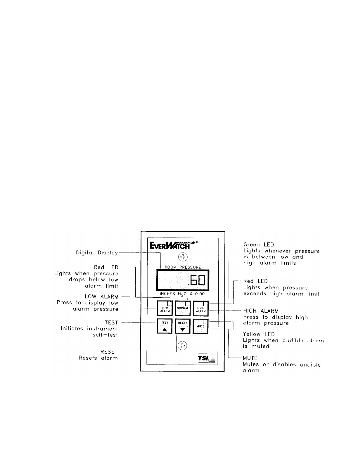
Figure 1. EVERWATCH Front Panel Display and Controls.

6
CHAPTER 2
Front Panel Digital Display
Display The digital display indicates the room pressure with respect to REFERENCED
CORRIDOR, calibration and configuration menus, and error messages. The
display indicates the room pressure continuously, the error messages when
they occur, and the calibration and configuration menu items when either of
these programming modes is selected.
Low Alarm Light
The red LOW ALARM light indicates low room pressure. The LOW ALARM light
turns on when the magnitude of the room pressure drops below, or is in the
opposite direction of the low room pressure alarm set point. When the lights
are configured for alarm follow operation, the LOW ALARM light remains on until
the room pressure returns to normal. When the lights are configured for alarm
latch operation, the LOW ALARM light remains on until the room pressure returns
to normal and the RESET key has been pressed.
Normal Light
The green NORMAL light indicates that the room pressure is in the normal range.
The NORMAL light is on when the room pressure is between the low room
pressure alarm set point and the high room pressure alarm set point.
High Alarm Light
The red HIGH ALARM light indicates high room pressure. The HIGH ALARM light
turns on when the magnitude of the room pressure exceeds in the same
direction as the high room pressure alarm set point. When the lights are
configured for alarm follow operation, the HIGH ALARM light remains on until
the room pressure returns to normal. When the lights are configured for alarm
latch operation, the HIGH ALARM light remains on until the room pressure returns
to normal and the RESET key has been pressed.
Mute Light
The yellow MUTE light indicates that the audible alarm is disabled. The MUTE
light turns on when the audible alarm has been disabled. The audible alarm
will not sound as long as the MUTE light is on.
Audible Alarm
The audible alarm indicates alarm conditions. The audible alarm sounds when
the room pressure is in an alarm condition. When the audible alarm is
configured for alarm follow operation, the alarm continues to sound until the
MUTE key is pressed or the room pressure returns to normal. When the audible
alarm is configured for alarm latch operation, the audible alarm remains on
until the MUTE key has been pressed, or the room pressure returns to normal
and the RESET key is pressed.
The audible alarm can also be muted by closing the contact closure input (pins
9-10 on back connector). With the contact closure input closed, the mute light
turns on and the audible alarm will not sound.

OPERATION
7
There is a 10 second delay between when the pressure triggers an alarm
and when the monitor shows the alarm condition. This is used so the
alarms don't trigger when someone opens a door to enter or leave the
room.
Front Panel The front panel controls operate as follows when configured
Controls using the standard factory installed default parameters:
LOW ALARM Key
The LOW ALARM key is used to display the low room pressure alarm set point on
the digital display. The low room pressure set point is displayed when the LOW
ALARM key is pressed.
NORMAL Key
The NORMAL key is used to gain access to the calibration and configuration
menus. Refer to Chapters 3 and 4 for configuration and calibration instructions.
HIGH ALARM Key
The HIGH ALARM key is used to display the high room pressure alarm set point on
the digital display. The high room pressure alarm set point is displayed when
the HIGH ALARM key is pressed.
TEST Key
The TEST key is used to initiate an instrument self-test. The monitor display,
indicator lights, audible alarm, and internal electronics are tested when the TEST
key is pressed.
RESET Key
The RESET key is used to reset the low and high room pressure alarm lights and
alarm contacts. Alarm lights and contacts are reset when the room pressure has
returned to normal and the RESET key is pressed. The RESET key is also used to
reset error messages. See the troubleshooting guide in Chapter 6 for details.
MUTE Key
The MUTE key is used to silence and/or disable the audible alarm. An audible
alarm can be silenced at anytime by pressing the MUTE key. The audible alarm
can be disabled by pressing the MUTE key when the audible alarm is not
sounding and the yellow MUTE light is off. The yellow MUTE light turns on when
the audible alarm has been disabled.
The mute light will turn on when the contact closure input is closed.
Pressing the MUTE key has no affect in this configuration.

8
CHAPTER 2

9
CHAPTER THREE
CONFIGURATION
The EVERWATCH is a very versatile device which may be set to operate in a
variety of configurations. This chapter is a guide for configuring the
EVERWATCH.
The configuration menu is used to select the low alarm set point, high alarm set
point, display period, alarm light response, alarm relay response, audible alarm
response, elevation correction and analog output resolution. The items to be
configured are arranged sequentially in the configuration menu. The
configuration data is stored in memory when the configuration menu is exited
and the EVERWATCH is returned to normal operation. A flow chart diagraming
the configuration procedure is included in Appendix D.
The EVERWATCH is shipped with a set of default values already programmed in
memory. These default values are listed on the Configuration Worksheet in
Table 1. Use the Configuration Worksheet to select the desired configuration
parameters for the intended application.
Table 1. EVERWATCH Configuration Worksheet.
Default User
Function Display Range/Options Value Value
Low Alarm L AL OFF, -195.00 to 195.00 OFF
inches H20 X 0.001 in 0.05,
0.50, 5.00 increments
depending on the magnitude of
the alarm.
High Alarm H AL OFF, -195.00 to 195.00 OFF
inches H2O X 0.001 in 0.05,
0.50, 5.00 increments
depending on the magnitude
of the alarm.
Display dSPL 2 to 10 seconds 5
Averaging Period (in 1 second increments)
Alarm light LEdS Latch (LA) or Follow (UnLA) LA
Alarm Relay rLYS Latch (LA) or Follow (UnLA) LA
Audible Alarm AUD Latch (LA) or Follow (UnLA) LA
Alarm Disable dSbL On or OFF On
Elevation ELEV 0 - 10,000 feet in 1000 0
feet increments
Analog Output AOUT 1, 10 and 100. 1 is maximum, 1
100 is minimum range
Access Code PASS On or OFF OFF

10
CHAPTER 3
The magnitude of the alarm increments changes with the
magnitude of the set point. ①When the magnitude of the
setpoint is less than 10.00 inches H20 X 0.001, the increments
equal 0.05 inches H20 X 0.001. ②When the magnitude of the
setpoint is between 10.00 and 100.00 inches H20 X 0.001, the
increments equal 0.50 inches H20 X 0.001. ③When the
magnitude of the setpoint is greater than 100.00 inches H20 X
0.001, the increments equal 5.00 inches H20 X 0.001.
Description of Display Function Description
Configuration
Menu
Functions COnF Configuration Menu The configuration menu
function indicates the
configuration menu is about to
be entered.
COdE Access Code The access code function
prevents unauthorized access to
the configuration menu. This
function is not enabled and is
not indicated on the display on
initial start-up. The access code
function is enabled by turning
the access code enable function
on (See PASS Below).
L AL Low Alarm The low alarm function is used
to set the low alarm set point.
The low alarm set point may be
set to OFF, or it may be set
between -195.00 and 195.00
inches H2O X 0.001. A low
room pressure alarm condition
is initiated when the magnitude
of the room pressure falls
below, or is in the opposite
direction of, the low alarm set
point.
H AL High Alarm The high alarm function is used
to set the high alarm set point.
The high alarm set point may
be set to OFF, or it may be set
between -195.00 and 195.00
inches H2O x 0.001. A high
room pressure alarm condition
is initiated when the magnitude
of the room pressure rises above
the high alarm set point.
There is a 0.50 inches H2O x 0.001 dead band between the low
alarm set point and high alarm set point which prevents the
alarm set points from overlapping. For example, when the low
alarm set point is set at .50 inches H2O x 0.001 the lowest the

CONFIGURATION
11
high alarm set point can be set is 1.00 inches H2O x 0.001. If the
magnitude of the alarms is greater than 100.00, the deadband
increases to 5.00 inches H20 x 0.001.
The alarm set points must have the same sign. Normal room
pressure should lie between the high and low alarm set points.
For example, if the low alarm is -0.50 inches H20 X 0.001, the
lowest high alarm set point is -1.00 inches H20 X 0.001.
dSPL Display Averaging The display averaging period
Period function is used to set the
display averaging period. The
display averaging period may
be set between 2 and 10
seconds. The display averaging
period is the period of time over
which the room pressure
readings are averaged before
being displayed. The longer the
display averaging period, the
more stable the display.
See Appendix B for an in-depth
description.
LEdS Alarm Light The alarm light function is used
to select whether the low and
high alarm lights latch in an
alarm condition(LA) or follow
an alarm condition(UnLA).
When alarm latch is selected,
the alarm light turns on in an
alarm condition and remains on
until the room pressure returns
to normal and the RESET key is
pressed. When alarm follow is
selected, the alarm light turns
on in an alarm condition and off
when the room pressure returns
to normal.
rLYS Alarm Relay The alarm relay function is used
to select whether the low and
high alarm relay latch in an
alarm condition(LA) or follow
an alarm condition(UnLA).
When alarm latch is selected,
the alarm relay contacts close in
an alarm condition and remain
closed until the room pressure
returns to normal and the RESET
key is pressed. When alarm
follow is selected, the alarm

12
CHAPTER 3
relay contacts close in an alarm
condition and open when the
room pressure returns to
normal.
Aud Audible Alarm The audible alarm function is
used to select whether the
audible alarm latches in an
alarm condition(LA) or follows
an alarm condition(UnLA).
When alarm latch is selected the
audible alarm turns on in an
alarm condition and remains on
until the room pressure returns
to normal and the RESET key is
pressed. When alarm follow is
selected the audible alarm turns
on in an alarm condition and off
when the room pressure returns
to normal.
dSbL Alarm Disable The alarm disable function is
used to select whether the
audible alarm can (On) or
cannot (OFF) be disabled from
the keypad.
ELEV Elevation Correction The elevation correction
function is used to correct
the pressure readings to
changes in air density that
occur at different elevations.
AOUt Analog Output This enables the user to select
Resolution the range of the analog output.
This value can be set to 1, 10, or
100. 1 represents a range from
-0.1 to 0.1 inches H20. 10
represents a range of -0.01 to
0.01 inches H20 and 100
represents a range from -0.001
to 0.001 inches H20.
PASS Access Code The access code enable function
is used to select whether an
access code is required (ON) or
not required (OFF) to enter the
configuration menu.
End End Configuration Identifies the end of the
configuration menu.

CONFIGURATION
13
SAVE Save The save function confirms that
any new values entered have
been saved to memory. Save is
displayed only when new
values have been entered.
Configuration The EVERWATCH is configured as follows:
Procedure
Enter the Configuration Menu
Press and hold the NORMAL key until CONF is indicated on the
display, then release the NORMAL key.
Press and release the NORMAL key to select the configuration
menu.
If L AL is indicated on the display, the access code enable
function is set to off and an access code is not required to enter
the configuration menu. Skip to the next page for instructions
descriping how to set the low alarm set point.
If COdE is indicated on the display, the password enable function
is set to on and an access code is required to gain access to the
configuration menu. Enter the configuration menu access code
as follows:.
Enter Configuration Menu Access Code
Press and release the LOW ALARM key.
Press and release the TEST key.
Press and release the RESET ALARM key.
Press and release the HIGH ALARM key.
Press and release the LOW ALARM key.
If the access code is entered correctly, the configuration menu is entered
and L AL is indicated on the display.
The configuration and the calibration access codes are not the
same. The configuration access code allows access to the
configuration menu only.
The access code must be entered within 40 seconds
(approximately eight seconds per keystroke). COdE flashes on
and off five times between keystrokes. If the next access code
key is not pressed within this time period, the configuration
menu is exited. The audible alarm sounds briefly each time a
keystroke has been entered. If an incorrect code is entered, an
error message (ERR) flashes on the display, the audible alarm
sounds and the configuration menu is exited.

14
CHAPTER 3
Set the Low Alarm Set Point
Confirm that L AL is indicated on the display.
Press and release the NORMAL key to display the current low
alarm set point.
Use the or keys to change the low alarm set point value.
Press and release the NORMAL key to save the displayed value.
L AL is indicated on the display.
Press and release the key to step to the next menu item.
Set the High Alarm Set Point
Confirm that H AL is indicated on the display.
Press and release the NORMAL key to display the current high
alarm set point.
Use the or keys to change the high alarm set point.
Press and release the NORMAL key to save the displayed value.
H AL is indicated on the display.
Press and release the key to step to the next menu item, or the
key to return to the previous menu item.
Set the Display Averaging Period
Confirm that dSPL is indicated on the display.
Press and release the NORMAL key to display the current display
averaging period.
Use the or keys to change the value of the display
averaging period.
Press and release the NORMAL key to save the displayed value.
dSPL is indicated on the display.
Press and release the key to step to the next menu item, or the
key to return to the previous menu item.
Table of contents


