CyClone DV160 User manual

SINGLE ROOM AIR HANDLING
UNITS WITH HEAT RECOVERY
Installation and Operation Instructions
Please read all instructions before installing and operating.
All wiring and installation must be in accordance with CEC, NEC and local electrical codes.
READ AND SAVE THESE INSTRUCTIONS
DV160

2DV160 Installation - English

3DV160 Installation - English
IMPORTANT SAFETY INSTRUCTIONS
UNIT MOUNTING SAFETY PRECAUTIONS
The unit must be disconnected from the
power supply prior to every installation or
repair operation.
The unit must be grounded!
The unit must not be operated outside the
temperature range stated in the user’s
manual or in aggressive or explosive
environments.
While installing the unit follow the safety
regulations specic to the use of electric
tools.
Do not change the power cord length at your
own discretion. Do not bend the power cord.
Avoid damaging the power cord.
Do not position any heating devices or
other equipment in close proximity to the
unit power cord.
Do not wash the unit with water. Protect the
unit electric parts from water ingress.
Use the unit only as intended by the
manufacturer. Do not connect clothes
dryers or similar equipment to the unit or
the ventilation system!
Disconnect the unit from power supply prior
to maintenance.
Do not damage the power cable while
operating the unit. Do not put any objects
on the power cable.
Do not open the operating unit. In case of unusual sounds, smoke
disconnect the unit from power supply and
contact the service centre.
In case of long lasting operation of the unit
check the mounting reliability periodically.
Do not block the air duct when the unit is
on.
• Read the user’s manual carefully prior to the operation and installation of the single-room heat recovery unit, hereinaer the unit.
• Installation and operation of the unit shall be performed in accordance with the present user’s manual as well as the provisions of
all the applicable local and national construction, electrical and technical codes and standards.
• e warnings contained in the present user’s manual must be considered most seriously since they contain vital personal safety
information.
• Failure to follow the safety regulations may result in an injury or unit damage.
• Read the manual carefully and keep it as long as you use the unit.
• While transferring the unit control the user’s manual must be turned over to the receiving operator.
WARNING
Symbol legend used in the manual:
WARNING!
DO NOT!
OFF
ON

4DV160 Installation - English
CONTENTS
Important Safety Instructions 3
About the product 5
Introduction 5
Use 5
Delivery set 5
Main technical parameters 5
Design and operating logic 7
Mounting and set-up 8
Connection to power mains 12
Unit control 13
Maintenance 13
Troubleshooting 14
Manufacturer’s warranty 15

5DV160 Installation - English
INTRODUCTION
is user’s manual includes technical description, operation, installation and mounting guidelines, technical data for the single-room
heat recovery air handling unit Cyclone DV160, hereinaer the unit.
USE
e single-room heat recovery air handling unit is an energy saving appliance based on heat recovery technology. It is one of the energy
saving components used in buildings and premises. e unit is a component part of a ventilation system and is not designed for stand-
alone operation.
e unit is designed to arrange permanent controllable air exchange in ats, cottages, hotels, cafes and other domestic and public premises.
e ltered air is warmed up by means of the recovered extract air heat energy.
e unit is designed for wall surface mounting.
e unit is rated for continuous operation.
Transported air must not contain any ammable or explosive mixtures, evaporation of chemicals, coarse dust, soot and oil particles,
sticky substances, brous materials, pathogens or any other harmful substances.
DELIVERY SET
a) DV160 unit - 1 item
b) Fastening set - 1 item
c) User’s manual - 1 item
d) Master plate - 1 item
e) Packing box - 1 item
f) Sensor or mechanical speed switch - 1 item
MAIN TECHNICAL PARAMETERS
The unit is designed for indoor application with the ambient temperature ranging from +1 °C (+34 °F) up to +40 °C (+104 °F) and relative humidity up to
80%.
The transported air temperature must be from -20 °C (-4 °F) up to +50° C (+122° F).
The unit is classied as a class I electric appliance.
Ingress Protection (IP) rating from solid objects and liquids:
• IP 44 for the unit motors;
• IP 22 for the assembled unit integrated into air ductworks.
The unit design is regularly improved, so some models may slightly differ from those ones described in this manual.
Imagine you could breathe fresh air all day while at the same time staying nice and warm, without unpleasant dras or open windows.
e Cyclone DIY air exchanger designed to continuously remove stale air from any space while simultaneously bringing in fresh air from
outside. Cyclone DIY air exchanger is a simple and ecient air recovery ventilator perfect for large rooms, such as los, condos or smaller
commercial spaces. Matches any style oce or home and saves lots of energy. Easy to install & plug in, simply drill two 5” diameter holes
through an exterior wall connect the damper to the unit and plug in. Any handy person can install this unit. No professionals required.
Get an HRV for an individual room without the cost and hassle of doing your entire home. Save money and target only the rooms that
need it most. Cyclone, breath better, live better.
ABOUT THE PRODUCT

6DV160 Installation - English
187 (7 3/8")
393 (15 1/2")
159 (6 1/4")
124
(4 7/8")
121
(4 3/4")
526 (20 11/16")
Speed 1 2 3
Supply Voltage, 50-60 Hz [V] 1 ~ 100-240
Power [W] 4.2 9.6 15.4
Total unit current [A] 0.02 0.04 0.07
Air capacity [m3 /h] (CFM) 30 (17.7) 45(26.5) 60(35.3)
RPM [min-1] 1165 1720 2685
Noise level [dB(A)] (Sones) 22(0.38) 25(0.42) 29(1.0)
Max. transported air temperature [°C] (°F) From -20 (-4) up to +50 (+122)
Ingress Protection IP22
Casing material Painted steel
Insulation PE foam
Filter: Extract G4
Supply G4
Connected air duct diameter [mm] Ø125 (5”)
Weight [kg] 10.3 (22.7)
Heat recovery efciency 79% 74% 70%
Heat exchanger type Counterow
Heat exchanger material Plastic
UNIT TECHNICAL DATA
UNIT OVERALL DIMENSIONS, MM

7DV160 Installation - English
DESIGN AND OPERATING LOGIC
Front panel - NV05
Supply fan - NV01S
Control unit - NV06
Extract fan - NV01E
Heat exchanger - NV04
Supply lter - NV03S
Extracr Filter - NV03E
• The unit casing is made of painted steel, internally lled with a layer of heat- and sound-insulating material.
• The unit casing incorporates a plate heat exchanger, a supply and an extract fan.
• The front panel is installed on the rotating sleeves to enable quick access for the unit servicing.
• The casing bottom is equipped with a protecting service panel to enable service access to the automation unit.
• The G4 supply lter is installed between the fan and the heat exchanger to provide supply of ltered air to the room. The G4 extract lter is installed in
the upper part of the front panel.
• The temperature sensor downstream of the heat exchanger in the exhaust air duct provides the heat exchanger freezing protection. If the exhaust air
temperature drops down below +3 ºC (+37.4 ºF) the heat exchanger freezing danger is registered. In this case the supply fan is turned off and the unit
operates in the extract mode only. After the heat exchanger is warmed up and the freezing danger is no longer imminent the unit reverts to the standard
operation mode.
Intake air
Exhaust air
Extract air
Supply air Unit operation logic.
Warm stale extract air from the room ows through the air ducts to the unit,
is puried in the extract lter, then it is moved to the heat exchanger and
exhausted outside by the extract fan. Clean cold air from outside is moved
by supply fans to the unit where it is puried through the supply lter. Then
clean air ows through the heat exchanger and is supplied to the room.
Heat energy contained in the warm extract air is transferred to the fresh
intake inside of the heat exchanger. Heat recovery minimizes heat energy
losses and operating heating costs

8DV160 Installation - English
MOUNTING AND SET-UP
The unit mounting is carried out with the master plate from the delivery set and two air ducts of required length or any of the mounting kits, MK1 DV160 or
MK2 DV160 (special accessories).
The mounting set MK1 DV160 is specially designed for mounting of the unit at general construction stage. It includes two plastic air ducts, 500 mm (19
11/16”) long and two master plates for marking holes on inner and outer wall sides.
The mounting set MK2 DV160 is specially designed for mounting of the unit in a ready-built premise. It includes two plastic air ducts, 500 mm (19 11/16”)
long, a master plate for marking holes and an outer ventilation hood NB DV160 that prevents ingress of foreign objects inside the unit. If the building’s wall
thickness is above 500 mm (19 11/16”) prepare two extra Ø 125 mm (Ø 5”) air ducts of required length.
PAPER MASTER PLATE FOR HOLE MARKING [MM] (INCHES)
drill 2 holes in the wall, 60 mm (2 3/8”)
deep, with a Ø 8 mm (Ø 5/16”) tool.
2 holes for the round Ø 125 mm (Ø 5”)
duct. Fill the gaps between the wall and
the air duct with a mounting foam.
239 (9 7/16")
160 (6 5/16")
503 (19 13/16")
89,5 (3 1/2")160 (6 5/16")
UNIT MOUNTING
Drill 2 holes in the wall,
60 mm (2 3/8”) deep,
with a Ø 8 mm (Ø 5/16”)
tool.
2 holes for the round Ø
125 mm (Ø 5”) duct. Fill
the gaps between the
wall and the air duct
with a mounting foam.
The unit is mounted as follows:
1. Fix the master plate from the delivery set on the wall with a sealing
tape on a required level.

9DV160 Installation - English
10 mm (3/8")
slope 3˚
Ø130 mm (5 1/8")
slope 3˚
60 mm (2 3/8")
2 holes
Ø 8 mm (5/16’’)
2 holes
2. Use a master plate to mark two Ø 130 mm (5 1/8”) holes for the air ducts and two Ø 8 mm (5/16”) holes for the dowels.
3. Remove the master plate and drill through holes for the air ducts and the 60 mm (2 3/8”) deep holes for the dowels. Drill the holes for the air ducts sloped
down by 2-3°. Then insert the dowels (included into delivery set) into respective holes.
4. Re-install the master plate with a sealing tape back. Fix the master plate
from the MK1 DV160 or MK2 DV160 mounting kit on outer wall side to align the
air ducts with respect to each other. Fix the master plate from the mounting kit
somewhat lower to ensure the minimum required slope 3°. Before mounting the
master plate press the perforated holes to remove the master plate fragments
and prepare holes for the air ducts.
5. Insert the air ducts inside the holes in the master plate designed for the air
ducts and seal those with a mounting foam through the holes in the master plate.
Install the air ducts sloped down by 2-3° to ensure the condensate drainage
from the unit.
6. After the mounting foam gets hard (see the solidication time in the product
specication) remove the master plate and cut off the protruding parts of the
air ducts to be ush with the inner wall. On outer wall side, the air ducts must
protrude for 10 mm (3/8’’) to prevent condensate dropping on the wall.
7. Unit installation sequence:
• Open the front panel and remove the heat exchanger.
• Connect the unit spigots to the plastic air ducts.
• Fix the unit to the wall with the screws 5,0x50 from the delivery set by inserting those to the Ø8 mm (5/16”) holes.
• Install the heat exchanger and close the front panel.
• Install the NB DV160 outer ventilation hood on outer side of the building to prevent ingress of large foreign objects into the air ducts
Attention! The round plastic air ducts and the outer ventilation hood are not included into the delivery set and are available on separate order.
You may use other ventilation grilles and hoods of the matching size.

10 DV160 Installation - English
MOUNTING WITH THE MK1 DV160 MOUNTING SET
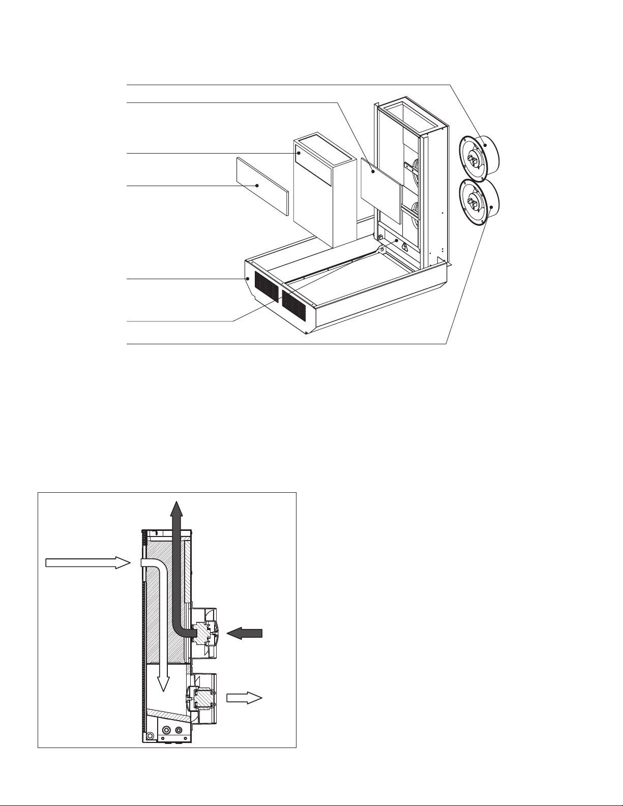
Wall
Outer ventilation hood
Round air duct
sloped down by 2-3°
Fasteners
DV160 unit
Round air duct sloped
down by 2-3°
The MK1 DV160 mounting set is designed to prepare a mounting
site for installation of the DV160 unit at general construction
stage. The set is not included into the delivery and is available
on separate order. The MK1 DV160 mounting set includes:
• Plastic air duct Ø 125 mm (Ø 5’’), 500 mm (19 11/16’’) long
- 2 items;
• Paper master plate - 2 items. Mounting sequence of the
MK1 DV160
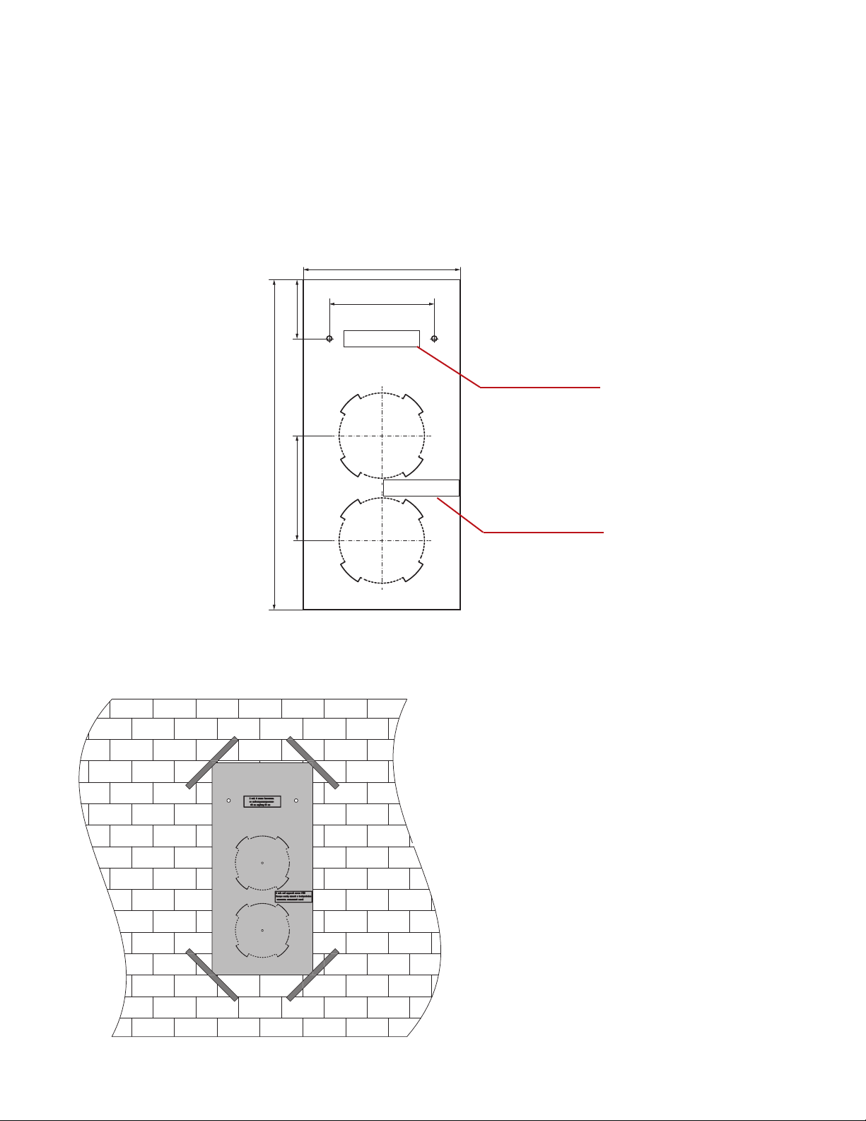
Mounting sequence of the MK1 DV160 set:
1. Fix the rst master plate on the inner wall side with a sealing
tape at a required height.
2. Use the master plate to mark two Ø 130 (5 1/8”) mm holes for
the air ducts and two Ø 8 mm (5/16”) holes for the xing dowels
of the unit.
3. Remove the master plate and drill through holes for the air
ducts and the holes, 60 mm (2 3/8”) deep for the dowels.
4. Re-install the rst master plate with a sealing tape back. Fix
the second master plate on the outer wall side to align the air
ducts with respect to each other. Fix the second master plate
somewhat lower to ensure the minimum slope 3° for the air
ducts. Before installation of the master plate press the marked
perforated opening on the master plate and remove the master plate cut-outs.
5. Install the air ducts into the master plate holes and seal those with a mounting foam through the openings in the master plate. Install the air ducts sloped
down by 2-3° to enable the condensate drainage.
6. After the mounting foam gets hard (see the solidication time in the product specication) remove the master plate and cut the protruding parts of the
air ducts to be ush with the inner wall. On the outer wall side, the air ducts must protrude by 10 mm (3/8’’) to prevent condensate dropping on the wall.
MOUNTING WITH THE MK2 DV160 MOUNTING SET
The MK2 DV160 mounting set is designed for the DV160 unit mounting and is available upon separate order. The MK2 DV160 mounting set includes:
• Plastic air duct Ø 125 mm (Ø 5’’), 500 mm (19 11/16’’) long - 2 items;
• Paper master plate - 1 item;
• NB DV160 outer ventilation hood - 1 item;
• 8x40 screw and dowel - 4 items.
Mounting sequence of the MK2 DV160 set:
1. Fix the master plate from the delivery set on the inner wall side with a sealing tape at the required height.
2. Use a master plate to mark two Ø 130 (5 1/8”) mm holes for the air ducts and two Ø 8 mm (5/16”) holes for the xing dowels of the unit.
3. Remove the master plate and drill through holes for the air ducts and the holes, 60 mm (2 3/8”) deep for the dowels.
4. Re-install the master plate with a sealing tape back. Fix the master plate from the mounting set on the outer wall side to align the air ducts with respect
to each other. Before installation of the master plate press the marked perforated opening on the master plate and remove the master plate cut-out.
5. Install the air ducts into the master plate holes and seal those with a mounting foam through the openings in the master plate. Install the air ducts sloped
down by 2-3° to enable the condensate drainage.
6. After the mounting foam gets hard (see the solidication time in the product specication) remove the master plate and cut off the protruding parts of the
air ducts to be ush with the inner wall. On the outer wall side, the air ducts must protrude by 10 mm (3/8’’) to prevent condensate dropping on the wall.
7. Install the outer ventilation hood NB DV160 on the outer wall side to prevent ingress of large foreign objects into the air ducts. Installation of the NB
DV160 outer hood is carried out with four 8x40 screws and dowels and is carries out as follows:
• Lean the NB DV160 outer ventilation hood against the wall;
• Mark fastening holes;
• Drill four Ø 8 mm (Ø 5/16”) holes, 40 mm (1 9/16’’) deep;
• Install 8x40 dowels;
• Install the NB DV160 ventilation outer hood;
• Fix the NB DV160 outer hood with screws.

11DV160 Installation - English
SPEED SWITCH MOUNTING
MAKE SURE THAT THE SPEED SWITCH IS NOT DAMAGED. DO NOT OPERATE A DAMAGED SPEED SWITCH! DO NOT
INSTALL THE SPEED SWITCH ON AN UNEVEN SURFACE! DO NOT APPLY EXCESSIVE FORCES WHILE TIGHTENING
THE SCREWS TO AVOID THE SPEED SWITCH CASING DEFORMATION.
WARNING
• Route all the required cables and wires to the speed switch installation place.
• Insert the junction box from the delivery set inside the wall.
P3-1-300 mechanical speed switch mounting:
• Connect the executive element according to the wiring diagram in page 12 and
insert it into the junction box.
• Fasten the executive element with two screws from the delivery set.
• Cover the executive element of the speed switch with a decorative panel and
press the latches to x the panel.
SP3-1 sensor speed switch mounting:
• Undo gently the switch front panel latches.
• Remove the back panel.
• Fix the back panel to the wall through the fastening openings.
• Connect the control cable to the sensor speed switch following the wiring
diagram, page 12.
• Install the front panel of the speed switch on the latches.

12 DV160 Installation - English
CONNECTION TO POWER MAINS
WIRING DIAGRAM FOR THE UNIT WITH P3-1-300 MECHANICAL SPEED SWITCH
1
1
2
3
4
5
PE
L
N
+12V
GND
+12V
+12V GNDD IR PWM+ 12VG ND DIRP WM
GND
PE
L
N
+
-
Cont .Circ. Stick.
Cont.Circ.
INFLOW_PWM
OUTFLOW_PWM
INFLOW_DIR
Stick.
5
4
3
2
1
2
2
1
1GND
NTC
M2
(supply)
M1
(extract)
RT1
t˚ NTC_10K
5
4
3
2
1
+
-
iD
iP
0P
NN
LL
L3
L2
L1
speed
3
speed
2
speed
1
2
3
N
L
PE
N
L
PE
N
L
PE
yellow-green
red
blue
yellow
white
red
blue
yellow
white
Cont .Circ. Stick.
Cont.Circ.Stick.
brown
yellow
green
white
High
Middle
Low
3 21
CONTROLLER
WIRING DIAGRAM FOR THE UNIT WITH SP3-1 SENSOR SPEED SWITCH
5
4
3
2
1
NN
LL
L3
L2
L1
speed
3
speed
2
speed
1
brown
yellow
green
white
OUTOUT OUTOUTI N
LL1L2L3L4
High
Middle
Low
DISCONNECT THE UNIT FROM POWER MAINS PRIOR TO ANY ELECTRIC INSTALLATION OPERATIONS. CONNECT
THE UNIT TO A CORRECT INSTALLED SOCKET WITH A GROUNDED TERMINAL.
ANY INTERNAL CONNECTION MODIFICATIONS ARE NOT ALLOWED AND RESULT IN WARRANTY LOSS.
WARNING
• The unit is rated for connection to single-phase ac 1~100-240 V/ 50-60 Hz power mains.
• The control unit is installed under the unit protecting panel.
• The unit is connected to the control unit via a 3 m long four-wire cable from the delivery set.
• Each wire cross section is min. 0.25 mm2.
• The maximum length of the cable from the unit to the control unit is 30 m

13DV160 Installation - English
SP3-1 SENSOR SPEED SWITCH
• To activate a required unit speed touch a respective speed button on the sensor panel.
— Low speed — Middle speed — High speed
• For speed changeover, touch a respective speed button. e active speed button glows blue.
• To turn the unit o touch a respective current speed button again. e sensor switch panel is not lighted when the
unit is o.
• e speed switch generates a sound signal each time the sensor panel is touched.
P3-1-300 MECHANICAL SPEED SWITCH
• To activate a required unit speed rotate the speed knob clockwise and select one of three
speed settings:
1 - low speed
2 - middle speed
3 - high speed
• To turn the unit o rotate the speed knob counter clockwise and set it to OFF position
UNIT CONTROL
3
O
12
3OFF
MAINTENANCE
DISCONNECT THE UNIT FROM POWER SUPPLY BEFORE ANY MAINTENANCE OPERATION WITH THE UNIT.
WARNING
The recommended unit maintenance periodicity is 3-4 times per year.
Maintenance of the unit means regular cleaning of the surfaces of dust and cleaning or replacement of the lters.
To remove dust use a soft brush, cloth or a vacuum cleaner. Do not use water, abrasive detergents, solvents, sharp objects. The impeller blades must be
cleaned once in year.
Clogged lters increase air resistance and impair the unit air capacity. Clean the lters with a vacuum cleaner or ush under running water. The lters must
be cleaned at least 3-4 times per year.
Casing
Heat exchanger
Front panel
Clean the heat exchanger regularly to maintain its high heat recovery efciency. Remove the heat exchanger of the unit prior to the cleaning operation.
Clean the heat exchanger with a vacuum cleaner or ush it under running water.

14 DV160 Installation - English
TROUBLESHOOTING
Issue Cause Solution
The fan does not start up. No power supply • Make sure that the unit is properly connected to the
power mains and make any corrections, if required.
The motor is jammed, the impeller blades are clogged. • Turn the unit off. Troubleshoot the motor jam.
• Clean the blades.
• Restart the unit.
Automatic switch tripping. Overcurrent resulted from short circuit in the electric
circuit
• Turn the unit off.
• Contact the service centre.
Low supply air temperature. The extract lter is clogged. Clean or replace the extract lter.
The heat exchanger is frozen • Check the heat exchanger for icing.
• Turn the unit off and let ice melt.
Low air ow. Low set fan speed. Set higher speed.
The lters, the fans or the heat exchanger is (are)
soiled.
• Clean or replace the lters.
• Clean the fan and the heat exchanger.
High noise, vibration. The impeller is soiled. Clean the impeller(s).
Loose screw connection. Tighten the screws.
No anti-vibration connectors are installed. Install the anti-vibration connectors (not included into
the delivery set).

15DV160 Installation - English
CYCLONE LIMITED WARRANTY
North America Range Hoods Inc. (hereunder called “e Company”) provides a warranty that its products are free from defects in
workmanship and materials for a period of ve (5) years from the date of purchase for the following models: DV160 and SV130, and for a
period of three (3) years for the following models: CG180, CG110. During that time period, e Company will, at the Company’s option,
repair or replace without charge any parts or complete unit found to be defective. is warranty is not transferable from the original
purchaser. e company reserves the right to use functionally equivalent reconditioned parts or products as warranty replacement or as
part of warranty service. Warranty does not cover the costs of removal, installation and/or transportation of defective products.
THE COMPANY WILL NOT BE HELD RESPONSIBLE FOR ANY CLAIMS OVER THE ORIGINAL PURCHASE PRICE OF
THE PRODUCTS NOR BE LIABLE FOR INCIDENTAL, CONSEQUENTIAL OR SPECIAL DAMAGES ARISING OUT OF OR IN
CONNECTION WITH PRODUCT USE OR PERFORMANCE.
Some provinces do not allow the exclusion or limitation of incidental or consequential damages, so the above limitation or exclusion may
not apply to you.
e unit removal and re-installation works are under the customer responsibility.
is warranty does not cover any costs related to the products including but not limited to:
a) Normal maintenance service required for the products; b) lters, roof caps, wall caps and other accessories for ducting; c) natural
wear of the nish of the products or wear caused by improper maintenance, use of corrosive and abrasive cleaning products; d) products
or parts which have been subject to freight damage, misuse, negligence, accident or any other circumstances beyond the control of e
Company.
e warranty will be automatically void if any of the following apply:
• Commercial use of the products or use otherwise inconsistent with its intended purpose;
• e function of part or the complete assembly has been modied or repaired by unauthorized person;
• Faulty installation or installation contrary to recommended installation instructions:
• Ventilation system has not been vented to the outside or ventilation system stuck;
• Less than 5” round or equivalent ductwork has been used anywhere in the venting system;
• e venting duct blocked anywhere in the venting system;
• Wrong electrical wire connection for the fan.
To qualify for warranty service you must: (a) notify us at the address telephone number stated below within 2 days of the discovery of the
defect; (b) provide the model number and serial number; and (c) describe the nature of any defect in the product or part.
At the time of requesting for service, you must present evidence of your proof of purchase and proof of the original purchase date. If
we determine that the warranty exclusions listed above apply or if you fail to provide the necessary documentation to obtain service,
customer will be responsible for all shipping, travel, labor and other costs related to the service
For warranty services or repair, please contact the dealer from whom you purchased the product or the address shown below.
North America Range Hoods Inc.
1361 Huntingwood Drive, Unit 16
Scarborough, ON M1S 3J1
Tel: 1-888-293-5662 or (416) 293-0933 Fax (416) 293-4793
Email: Info@CycloneRangeHoods.com
Website: www.CycloneRangeHoods.com

Centrale de traitement d’air à récupération
de chaleur pour pièce unique
Instructions d’Installation et d’Utilisation
Veuillez lire toutes les instructions avant d’installer et d’utiliser la hotte.
Les travaux d’installation et les branchements électriques doivent satisfaire aux exigences du Code
canadien de l’électricité (CCE) et du National Electric Code (NEC) ainsi que des codes municipaux.
LISEZ ET CONSERVEZ CES INSTRUCTIONS.
DV160
3166456

2Installation d’une DV160 - Français

3Installation d’une DV160 - Français
INSTRUCTIONS DE SÉCURITÉ IMPORTANTES
MESURES DE SÉCURITÉ POUR LE MONTAGE DE L’UNITÉ
Débranchez l’unité de la source
d’alimentation avant l’installation ou avant
d’effectuer une réparation.
L’unité doit être mise à la terre!
Utilisez l’unité dans un endroit dont la
température se situe dans la fourchette
indiquée dans le manuel de l’utilisateur.
Ne l’utilisez pas dans des endroits au
climat difcile ou en présence d’explosifs.
Lors de l’installation, respectez les
mesures de sécurité portant sur l’utilisation
d’outils électriques.
Ne changez pas la longueur du cordon
d’alimentation à votre discrétion. Ne pliez
pas le cordon d’alimentation et évitez de
l’endommager.
Ne placez aucun appareil de chauffage ou
autre équipement à proximité du cordon
d’alimentation de l’unité.
Ne nettoyez pas l’unité avec de l’eau.
Évitez les inltrations d’eau dans les
composants électriques de l’unité.
N’utilisez l’unité qu’aux ns prévues par le
fabricant. Ne branchez pas de sécheuses
ou d’équipement similaire à l’unité ou au
système de ventilation!
Débranchez l’unité de la source
d’alimentation avant l’entretien.
Évitez d’endommager le câble
d’alimentation alors que l’unité est en
marche. Ne placez aucun objet sur le câble
d’alimentation.
N’ouvrez pas l’unité opérationnelle. Si vous entendez un bruit inhabituel, ou
si vous détectez de la fumée, débranchez
l’unité de la source d’alimentation et
communiquez avec le centre de service à
la clientèle.
Si l’unité sert pour une période prolongée,
procédez à une vérication périodique du
montage pour détecter tout problème.
Ne bloquez pas la conduite d’air lorsque
l’unité est en marche.
• Lisez le manuel de l’utilisateur attentivement avant d’installer et d’utiliser la centrale de traitement d’air à récupération de
chaleur pour pièce unique (ci-après « l’unité »).
• Lors de l’installation et de l’utilisation de l’unité, vous devez vous conformer au présent manuel de l’utilisateur et aux conditions
des normes et codes locaux et nationaux pertinents aux domaines de la construction, de l’électricité et de l’ingénierie.
• Les avertissements donnés dans le présent manuel de l’utilisateur doivent être pris en considération avec sérieux puisqu’ils
fournissent des renseignements essentiels concernant la sécurité personnelle.
• Le fait de ne pas respecter les exigences de sécurité pourrait entraîner des blessures ou causer des dommages à l’unité.
• Lisez le manuel attentivement et conservez-le aussi longtemps que vous utiliserez l’unité.
• Si une autre personne devient responsable du contrôle de l’unité, le manuel de l’utilisateur doit lui être remis.
AVERTISSEMENT
Légende des symboles utilisés dans le manuel :
MISE EN GARDE!
À NE PAS FAIRE!
OFF
ON

4Installation d’une DV160 - Français
TABLE DES MATIÈRES
Instruction de sécurité importantes 3
À propos du produit 5
Introduction 5
Utilisation 5
Ensemble à la livraison 5
Paramètres techniques principaux 5
Conception et logique de fonctionnement 7
Montage et mise en place 8
Connexion au réseau électrique 12
Unité de contrôle 13
Entretien 13
Dépannage 14
Garantie Limitée de Cyclone 15

5Installation d’une DV160 - Français
INTRODUCTION
Ce manuel de l’utilisateur comprend une description technique, des renseignements sur le fonctionnement, des instructions pour
l’installation et le montage, et des données techniques concernant la centrale de traitement d’air à récupération de chaleur pour pièce
unique DV160 Cyclone, (ci-après « l’unité »).
UTILISATION
La centrale de traitement d’air à récupération de chaleur pour pièce unique est un appareil éconergétique dont le fonctionnement est
fondé sur la technologie de récupération de la chaleur. Il s’agit de l’un des éléments utilisés dans les bâtiments et établissements aux ns
d’économie d’énergie. L’unité est un élément du système de ventilation et n’est pas conçue pour fonctionner de façon autonome.
L’unité est conçue pour être ajoutée aux échangeurs d’air permanents et contrôlables dans des appartements, des chalets, des hôtels, des
cafés et autres installations à usage domestique ou public. L’air ltré est réchaué par l’énergie de la chaleur récupérée.
L’unité est conçue pour un montage mural.
L’unité peut soutenir un fonctionnement continu.
L’air ambiant ne doit pas contenir de particules explosives ou inammables, de vapeurs provenant de produits chimiques, de grosses
poussières, de suie ou de particules huileuses, de substances collantes, de matières breuses, de pathogènes ou d’autres substances
dangereuses.
ENSEMBLE À LA LIVRAISON
a) Unité DV160 – un article
b) Ensemble pour xation – un article
c) Manuel de l’utilisateur – un article
d) Patron – un article
e) Boîte d’emballage – un article
f) Capteur ou commutateur de vitesse mécanique – un article
PARAMÈTRES TECHNIQUES PRINCIPAUX
L’unité est conçue pour une utilisation intérieure dans un endroit au sein duquel la température ambiante se situe entre 1 °C (34 °F) et 40 °C (104 °F) et
où le taux d’humidité relative n’excède pas 80 %.
La température de l’air en circulation doit se situer entre -20 °C (-4 °F) et 50 °C (122 °F).
L’unité est un appareil électrique de classe I.
Indices de protection (IP) contre l’inltration d’objets solides et de liquides :
• IP 44 pour le groupe moteur;
• IP 22 pour l’unité assemblé et intégré au réseau de ventilation.
La conception du produit est continuellement améliorée, raison pour laquelle certains modèles peuvent légèrement différer de ceux décrits dans ce manuel.
À PROPOS DU PRODUIT
Imaginez pouvoir respirer de l’air frais toute la journée, tout en restant bien au chaud, sans courants d’air désagréables ou fenêtres ouvertes.
Le ventilateur-récupérateur thermique (VRT) DIY de Cyclone est conçu pour éliminer continuellement l’air vicié de n’importe quel espace
tout en apportant simultanément de l’air frais de l’extérieur. Le VRT DIY de Cyclone est un ventilateur-récupérateur thermique simple
et ecace, idéal pour les grandes salles, comme les los, les copropriétés ou les petits espaces commerciaux. Il correspond à n’importe
quel style de bureau ou de domicile, et économise beaucoup d’énergie. Facile à installer et à brancher, il sut de percer deux trous de 12,7
cm (5 po) de diamètre dans un mur extérieur, de relier l’amortisseur à l’appareil et de brancher. Toute personne peut facilement installer
cette unité. Aucun professionnel n’est requis. Obtenez un VRT pour une pièce individuelle sans le coût et les tracas d’aménager toute
votre maison. Économisez de l’argent et ciblez uniquement les chambres qui en ont le plus besoin. Cyclone : mieux respirer, mieux vivre.
Table of contents
Languages: