EVGA Z490 FTW User manual

EVGA Z490 FTW (122-CL-E497)
- 1 -
User Guide
EVGA Z490 FTW
Specs and Initial Installation

EVGA Z490 FTW (122-CL-E497)
- 2 -
Table of Contents
User Guide...............................................................................................................- 1 -
Before You Begin… .................................................................................................- 4 -
Parts NOT in the Kit............................................................................................................. - 5 -
Intentions of the Kit.............................................................................................................. - 5 -
Motherboard.............................................................................................................- 6 -
Motherboard Specifications.................................................................................................. - 6 -
Unpacking and Parts Descriptions...........................................................................- 8 -
Intel®Z490 FTW Motherboard LED reference.................................................................... - 9 -
Intel®Z490 FTW Motherboard Component Legend.......................................................... - 11 -
PCIe Slot Breakdown ......................................................................................................... - 23 -
M.2 Slot Breakdown........................................................................................................... - 23 -
Installing the CPU .............................................................................................................. - 24 -
Installing the CPU Cooling Device .................................................................................... - 25 -
Installing System Memory (DIMMs) ................................................................................. - 26 -
Installing the I/O Shield...................................................................................................... - 27 -
Installing the Motherboard......................................................................................- 27 -
Securing the Motherboard into a System Case................................................................... - 28 -
Installing M.2 devices.............................................................................................- 30 -
Installing M.2 Key-M Socket 3 Devices ............................................................................ - 30 -
Tested CPU......................................................................................................................... - 33 -
Tested Memory................................................................................................................... - 33 -
Tested M.2 Key-M ............................................................................................................. - 34 -
Tested M.2 Key-E............................................................................................................... - 35 -
Connecting Cables.............................................................................................................. - 36 -
Onboard Buttons................................................................................................................. - 49 -
First Boot................................................................................................................- 50 -

EVGA Z490 FTW (122-CL-E497)
- 3 -
M.2 SSD, PCIe SSD, and NVMe SSD Installation steps ................................................... - 52 -
Internal RAID Controller.........................................................................................- 54 -
Fan Header and PWM Setup.................................................................................- 90 -
Setting Up SLI and PhysX......................................................................................- 94 -
Realtek HD Audio Manager............................................................................................... - 99 -
EVGA NU Audio...................................................................................................- 117 -
The NU Audio Control Panel ........................................................................................... - 120 -
NU Audio Custom Settings:............................................................................................. - 128 -
Installing Drivers and Software ............................................................................- 139 -
Windows 10 Driver Installation........................................................................................ - 139 -
Warranty and Overclocking.............................................................................................. - 141 -
Troubleshooting ...................................................................................................- 142 -
Flashing the BIOS ............................................................................................................ - 142 -
Flashing the BIOS Without a CPU................................................................................... - 145 -
SSD / HDD is not detected............................................................................................... - 146 -
System does not POST, and POST code indicator reads “C”........................................... - 148 -
System does not POST, and POST code indicator reads “55” ......................................... - 149 -
System does not POST, and POST code indicator reads “d7” ......................................... - 149 -
Have a question not covered above, or want some online resources? .............................. - 150 -
Multifunction LED Indicator............................................................................................ - 151 -
POST Beep codes............................................................................................................. - 153 -
POST Port Debug LED .................................................................................................... - 154 -
POST Codes........................................................................................................- 155 -
EVGA Glossary of Terms ................................................................................................ - 160 -
Compliance Information.......................................................................................- 163 -

EVGA Z490 FTW (122-CL-E497)
- 4 -
Before You Begin…
The EVGA Z490 FTW is ready for the latest 10th Gen Intel®Core™i9
processors. The 10th Gen Intel®Core™desktop processor platform provides an
optimal balance of frequency, cores and threads, advanced tuning support, and
blazing connectivity to supercharge desktops for a competitive edge. Featuring a
variety of high-speed data and storage options, display output options, 7.1
Channel Audio, and Intel®wired/wireless network options, the Z490 FTW has
everything you need. This board earns its FTW with a highly-efficient Digital
VRM connected to a 14 Phase power design, metal-reinforced PCIe slots, and
EVGA’s latest GUI BIOS featuring OC Robot and an in-BIOS stress test. The
EVGA Z490 FTW is the core of everything you do next.
Furthermore, this board is designed not only for overclockers, but also for
gamers by being NVIDIA®SLI®Ready and featuring blazing-fast networking,
Dual M.2 Key-M slots and much more!
Lastly, a motherboard is only as good as its BIOS, and the EVGA Z490 FTW
features EVGA’s newest UEFI/BIOS GUI with a focus on overclocking and
functionality in a lean, straightforward package. You won’t need to be an expert
to configure your motherboard, but if you are, you’ll find features unavailable
anywhere else.
Combining the best of current technology with the latest innovations, EVGA is
further refining motherboard performance!

EVGA Z490 FTW (122-CL-E497)
- 5 -
Parts NOT in the Kit
This kit contains all the hardware necessary to install and connect your new
EVGA Z490 FTW Motherboard. However, it does NOT contain the following
items, which must be purchased separately in order to make the system fully-
functional and install an Operating System:
❑Intel® Socket 1200 Processor
❑DDR4 System Memory
❑CPU Cooling Device
❑PCI-Express Graphics Card
❑Power Supply
❑Hard Drive or SSD
❑Keyboard / Mouse
❑Monitor
❑(Optional) Optical Drive
EVGA assumes you have purchased all the necessary parts needed to allow for
proper system functionality. For a full list of supported CPUs on this
motherboard, please visit https://www.evga.com/support/motherboard.
Intentions of the Kit
When replacing a different model motherboard in a PC case, you may need to
reinstall your operating system, even though the current HDD/SSD may
already have one installed. Keep in mind, however, you may sometimes also
need to reinstall your OS after a RMA even if your motherboard remains the
same due to issues that occurred prior to replacing the motherboard.

EVGA Z490 FTW (122-CL-E497)
- 6 -
Motherboard
Motherboard Specifications
❑Size:
ATX form-factor of 12 inches x 9.6 inches (305x243.8mm)
❑Microprocessor support:
Intel®Socket 1200 Processor
❑Operating Systems:
Supports Windows 10 64-Bit
❑Contains Intel®Z490 chipset
❑System Memory support:
Supports up to 128GB Dual channel DDR4 up to 4400MHz+ (OC).
❑USB 2.0 Ports:
4x internal from 2 FP headers via Intel®Z490 USB HUB
1x from Update Port for flashing the BIOS without CPU
Supports hot plug/wake-up from S3 mode
❑USB 3.2 Gen.1 Ports:
4x from Intel®Z490 PCH –2x external (Type-A), 2x internal via 1 FP header
Supports transfer speeds up to 5Gbps
Backwards-compatible USB 2.0 and USB 1.1 support
❑USB 3.2 Gen.2 Ports:
5x from Intel®Z490 PCH –4x external (Type-A), 1x internal header
Supports transfer speeds up to 10Gbps
Backwards-compatible USB 3.2 Gen.1, USB 2.0 and USB 1.1 support
❑USB 3.2 Gen.2x2 Port:
1x from ASMedia ASM3242 –1x external (Type-C)
Supports transfer speeds up to 20Gbps
Backwards-compatible USB 3.2 Gen2/1, USB 2.0 and USB 1.1 support

EVGA Z490 FTW (122-CL-E497)
- 7 -
❑Display Outputs:
Display Port 1.2 / HDMI 1.4
❑SATA Ports:
4x SATA 6Gbps data transfer rate / Intel®Z490 PCH Controller
- Support for RAID0, RAID1, RAID5, AND RAID10
- Supports hot plug
2x SATA 6Gbps data transfer rate / ASMedia ASM1061 Controller
❑Onboard LAN:
Intel®i219V Gigabit NIC
Intel®Dual-Band WiFi / BT
❑Onboard Audio:
Realtek ALC1220 High Definition Audio + EVGA NU Audio
Supports 7.1 Channel HD Audio + Optical Out
❑Power Functions:
Supports ACPI (Advanced Configuration and Power Interface)
Supports S0 (normal), S3 (suspend to RAM), S4 (Suspend to disk - depends
on OS), and S5 (soft - off)
❑PCI-Express Expansion Slots:
1x PCIe x16/8 slot, 1x PCIe x8
1x PCIe x1 slot
❑PCIe 3.0 Support:
Low power consumption and power management features
❑SLI and Crossfire Support:
NVIDIA®SLI®Ready, 2-Way Crossfire
❑Additional Expansion Slots:
2x M.2 Key-M 110mm slot /1x M.2 Key-E slot
❑Fan Headers:
2x 4-pin PWM controlled headers / 5x 4-pin PWM/DC controlled headers
ALL FAN HEADERS HAVE A MAXIMUM POWER
LIMIT OF 2 AMP @ 12 VOLTS (24 WATTS)
EXCEDING THIS LIMIT WILL CAUSE
IRREPARABLE DAMAGE TO THE BOARD.

EVGA Z490 FTW (122-CL-E497)
- 8 -
Unpacking and Parts Descriptions
The following accessories are included with the EVGA Z490 FTW
Motherboard:

EVGA Z490 FTW (122-CL-E497)
- 9 -
Intel®Z490 FTW Motherboard LED reference
The EVGA Z490 FTW Motherboard has an LED to indicating power, connectivity, and
activity. Below is the location of the LED and its function.
1. Power / Reset Buttons 3. +5VSB 5. Onboard ARGB LED
2. POSTLED Indicator / Monitor 4. CATERR_LED 6. Active BIOS LED
LED Component Legend

EVGA Z490 FTW (122-CL-E497)
- 10 -
1. Power / Reset Buttons
a. Power Button
i. RED: Motherboard is turned on and running
b. Reset Button
i. White: Reset button will typically flash in conjunction with
HDD/SSD LED. Depending on load, the button may flash or
appear solid white at times.
ii. NVMe SSDs cannot be read for the purposes of the Reset LED.
2. Multifunction POST Indicator
a. During boot it will cycle many different hexadecimal post codes with a
range of 00-FF and this indicates what aspect of the Power On Self Test
(POST) is currently running.
i. For a list of POST Codes, please see Page 155.
ii. This indicator can be configured in BIOS to display hardware
monitoring information, such as voltage or temperature. After
boot, these LEDs will show either temperature or voltage,
depending on user configuration in the BIOS.
3. +5VSB
a. White: Voltage present (Does not mean PSU is outputting in-spec, only
that this specific voltage is detected)
4. CATERR_LED - Catastrophic Error on the processor
a. RED: Processor error has occurred.
b. OFF: No error state detected in the CPU.
5. Active BIOS LED
a. BIOS 1
i. WHITE: BIOS 1 chip is active
ii. OFF: BIOS 2 chip is active
b. BIOS 2
i. WHITE: BIOS 2 chip is active
ii. OFF: BIOS 1 chip is active
6. Onboard ARGB LED
a. Located around the PCH heatsink, the LEDs can be directly controlled
via EVGA ELEET X1. Choose the LED colors and patterns, or turn
off in the software.

EVGA Z490 FTW (122-CL-E497)
- 11 -
Intel®Z490 FTW Motherboard Component Legend
The EVGA Z490 FTW Motherboard with the Intel®Z490 and PCH Chipset.
Figure 1 shows the motherboard and Figure 2 shows the back panel connectors.
FIGURE 1. Z490 FTW Motherboard Layout
**For a FULL description of the above legend, please see Page 14.

EVGA Z490 FTW (122-CL-E497)
- 12 -
1. CPU Socket 1200 1 1. M.2 Socket 3 Key-M110mm 21. USB 2.0 Headers
2. Intel Z490 PCH 1 2. PCIe Slot x16/x8 22. Front Panel Audio Connector
3. PWM Fan Headers (1 amp) 1 3. PCIe Slot x8 23. PC Speaker
4. DC / PWM Fan Headers 1 4. PCIe Slot x1 24. Front Panel Connectors
5. DDR4 Memory DIMMSlots 1 5. ARGB LED Controller Header 25. CMOS Battery
6. 24-pin ATX power connector 1 6. RGB LED Controller Header 26. USB 3.2 Gen2 Header (Type-C)
7. 8-pin EPS Connector 1 7. Power Button 27 USB 3.2 Gen1 Header
8.
4-pin Supplemental ATX Connector
1 8. Reset Button 28 BIOS SafeBoot Button
9. Intel® Sata 6G Ports 19. POST Indicator / HW Monitor 29. BIOS Selector Switch
10.
ASMedia SATA 6G Ports 20. USB to SPI for BIOS Flash 30. Rear Panel Connectors (Figure 2)
Component Legend

EVGA Z490 FTW (122-CL-E497)
- 13 -
Figure 2. Chassis Rear Panel Connectors
1. BIOS /CMOS Reset 5. USB 3.2 Gen1 Ports 9. USB 3.2 Gen2x2 Port
2. Display Port 1.2 6. Integrated WiFi Module 10. Optical Out
3. HDMI 1.4 7. Intel i219V NIC 11. Analog Audio Jacks
4. PS/2 Port 8. USB 3.2 Gen2 Ports
I/O Hub Legend
Analog Audio Port
Breakdown
2/2.1 Channel 4.0/4.1 Channel 5.1 Channel 7.1 Channel
Blue Line In *Rear Speakers Out Line In
*Rear Speakers Out
Front Speakers Out /
Front Speakers +Sub
Front Speakers +Sub
Pink Mic In Mic In Mic In
Mic In
Black Side Speakers Out Side Speakers Out
Orange Center / Sub Out Center / Sub Out
3.5mm Audio Jack Legend
Front Speakers Out
Green
Front Speakers Out
*Only used in 7.1 and is changed via Realtek Software from within Windows.

EVGA Z490 FTW (122-CL-E497)
- 14 -
Component Legend Descriptions
1. CPU Socket 1200
This is the interface for the Central Processing Unit (CPU), and supports Core
i5, Core i7, and Core i9 models compatible with the Intel®1200 Socket and
Comet Lake-S architecture.
2. Intel®Z490 PCH (Southbridge)
The Platform Controller Hub (PCH) handles the role that was previously held
by the South Bridge. The PCH has 4 PCIe Gen 3 lanes and allocates bandwidth
to smaller PCIe slots, M.2, USB, audio, etc. In simplified terms, the PCH works
as a hub for peripherals that are less bandwidth-intensive.
3. PWM Fan Headers (CPU1 and CPU2)
4-pin fan headers that control the fan speed based on a configurable curve or
static percentage. PWM (Pulse-Width Modulation) works by pulsing power to
the fan at a constant rate and sending the RPM signal to the fan’s controller via
a Sense cable, rather than adjusting fan speed by increasing and decreasing
voltage. This method is preferable because it eliminates voltage-based fan stall
points. Please see Page 90 for a more in-depth PWM breakdown and PWM
controls within BIOS/UEFI.
These headers also support 12v. DC fans. However, DC fan speed is based on
decreasing voltage to the fan, starting at a default of 100%/12V. When using a
12v. fan, the minimum speed will vary depending on the motor because most
fan motors require a set amount of voltage before stalling.
4. PWM/DC Fan Headers
These ports may be used with both PWM and DC fans and may be controlled
via Smart Fan or manually within the BIOS.
5. DDR4 Memory Slots
The memory slots support up to four 288-pin DDR4 DIMMs in Dual-Channel
mode. Dual-Channel mode will be enabled only upon using two or four sticks
of supported memory, according to the installation guide above. Using one or
three sticks of memory will lower the board to Single-Channel mode, which
may significantly lower performance. Memory kits marketed as “Quad-
Channel” *MAY* work; however, the kit will continue to run in Dual-Channel
mode due to the limitations of the CPU’s memory controller. 128GB of RAM
is supported in a 4x32GB configuration. At the time of this manual’s release,
this motherboard officially supports up to 4400MHz+ speeds. These speeds

EVGA Z490 FTW (122-CL-E497)
- 15 -
cannot be guaranteed, however, because Intel®only certifies the speed of the
memory controller up to 2933MHz for Comet Lake-S processors.
6. 24-pin ATX power connector
The main power for the motherboard is located on the right side of the board
and perpendicular to the PCB; this is also described as a “Vertical” connector
(See Page 37 for more specifics to the connector itself, and associated
wiring/pinouts). The 24-pin connector IS directional and the connector needs
the tab on the socket to line up with the release clip located on the 24-pin
connector from the power supply. This connector pulls the bulk of the power
for all components. Other connectors, such as EPS and ATX, have been added
to reduce the load and increase longevity due to wiring and trace limitations.
7. 8-pin EPS Connector
The EPS is dedicated power for the CPU (See Page 38 for more specifics to the
connector itself, and associated wiring/pinouts). Carefully choose the correct
power cable by consulting with the installation manual for your power supply.
This connector is designed to only work with an EPS or CPU cable. System
builders sometimes make the mistake of plugging in a PCIe 8-pin or 6+2-pin
connector, which will prevent the board from completing POST and possibly
short or damage the board. Although PCIe and EPS cables appear similar, they
are wired differently and attaching the wrong connector may cause damage to
the motherboard.
Alternatively, if no power cable is connected or detected, the system will not
POST and will hang at POST code “C.”
8. 4-pin Supplemental ATX Connector
The ATX power connector on the Z490 FTW provides additional power to the
CPU. This connector requires the appropriate 4-pin ATX power that is
provided by your power supply –often as part of a 4+4-pin CPU connector.
(See Page 36 for more specifics to the connector itself, and associated
wiring/pinouts). This connector is not essential to running the system, but may
provide additional power to the CPU under a heavy load, overclocking, and/or
benchmarking. The 4-pin power connector may be installed in addition to the 8-
pin EPS connector; it may not be installed in place of the 8-pin EPS connector.
9. Intel®SATA 6G Ports
The Intel®Z490 PCH has a 4-port SATA 3/6G controller (See Page 48 for
specifics on the connectors). This controller is backwards compatible with
SATA and SATA 2 devices, and supports SSDs, HDDs and various types of
optical devices (CDROM, DVDROM, BD-ROM, etc.). The controller also

EVGA Z490 FTW (122-CL-E497)
- 16 -
supports NCQ, TRIM, hot swap capability (provided the proper HDD/SSD
bays/racks are installed), and RAID levels 0/1/5/10.
10. ASMedia SATA 6G Ports
This is a secondary SATA controller, the ASM1061 is a 2-port SATA3/6
Gbit/s controller with legacy support for older operating systems. This is
included largely for benchmarking and overclocking with very specific
programs, such as Super Pi, 3DMark, PCMark, etc. This board is not
guaranteed to fully support any OS prior to Windows 10 x64, as we offer no
drivers for legacy OS (See Page 48 for specifics on the connectors).
11. M.2 Socket 3 Key-M 110mm
M.2 is an SSD standard, which uses up to four PCIe lanes and utilizes Gen3
speeds. Most popularly paired with NVMe SSDs, this standard offers
substantially faster transfer speeds and seek time than SATA interface
standards. All M.2 devices are designed to connect via a card-bus style
connector, secured by bolting into place, and powered by the connector –rather
than a dedicated data cable and power cable.
M.2 Key-M (1) supports PCIe devices, while M.2 Key-M (2) supports both
PCIe and SATA devices.
This socket will support Key-M devices of 110mm, 80mm, 60mm, and 42mm
length.
12. PCIe Slot x16/x8
PCIe x16/x8 slots are primarily for video cards. These full-length slots will
provide 8 or 16 lanes of bandwidth to a full-size card, and are backwards-
compatible with x8, x4, and x1-length cards.
Comet Lake-S Socket 1200 processors have 16 PCIe lanes available for routing.
The 16 PCIe lanes are pulled from the CPU and shared with the x16 PCIe slot 2
(PE2). Lanes automatically switch from x16/x0 to x8/x8 when the
motherboard detects a card in slot PE2.

EVGA Z490 FTW (122-CL-E497)
- 17 -
13. PCIe Slot x8
PCIe x16/x8 slots are primarily for video cards. These full-length slots will
provide up to 8 lanes of bandwidth to a full-size card, and are backwards
compatible with x8, x4, and x1 length cards.
This slot is limited to a maximum of 8 lanes as it shares bandwidth with the
primary PCIe x16 slot 2 (PE1). This slot is primarily recommended for
secondary video cards, such as the 2nd card in a SLI configuration, or a PhysX
card.
* Please see the description for Physical (length) vs Electrical (lanes) on Page 21.
14. PCIe Slot x1
PCIe x1 is the smallest form-factor PCIe card slot. They are all one lane and
are used for low-bandwidth products.
15. ARGB LED Controller Header
The ARGB header is a 5V. 3 pin header with a current limit of 2A; anything
above 2A will trigger overcurrent protection and lock at 2A. This header allows
for far more flexible options to configure your RGB lighting via software-based
control within Windows via EVGA ELEET X1, and supports up to 125 LEDs.
Please see Page 42 for header specifics, and Page 137 for control options in
ELEET X1.
16. RGB LED Controller Header
The RGB header is a 12V. 4 pin header with a current limit of 2A; anything
above 2A will trigger overcurrent protection and lock at 2A. This header allows
for software-based control within Windows for RGB devices via EVGA
ELEET X1. Please see Page 43 for header specifics, and Page 137 for control
options in ELEET X1.
17. Power Button
This is an onboard power button, and may be used in place of, or in
conjunction with, a front panel power button wired to the board.
Benching systems, or test benches before final assembly, are best served by
using the onboard power because it removes the need to wire a Power/Reset
button or cross posts with a screwdriver, which is a semi-common practice.
This button provides a safer and easier option than jumpering the Power posts.
18. Reset Button
This is an onboard system reset button, and may be used in place of, or in
conjunction with, a front panel system reset button wired to the board.

EVGA Z490 FTW (122-CL-E497)
- 18 -
Benching systems, or test benches before final assembly, are best served by
using the onboard power because it removes the need to wire a Power/Reset
button or cross posts with a screwdriver, which is a semi-common practice.
This button provides a safer and easier option than jumpering the Power posts.
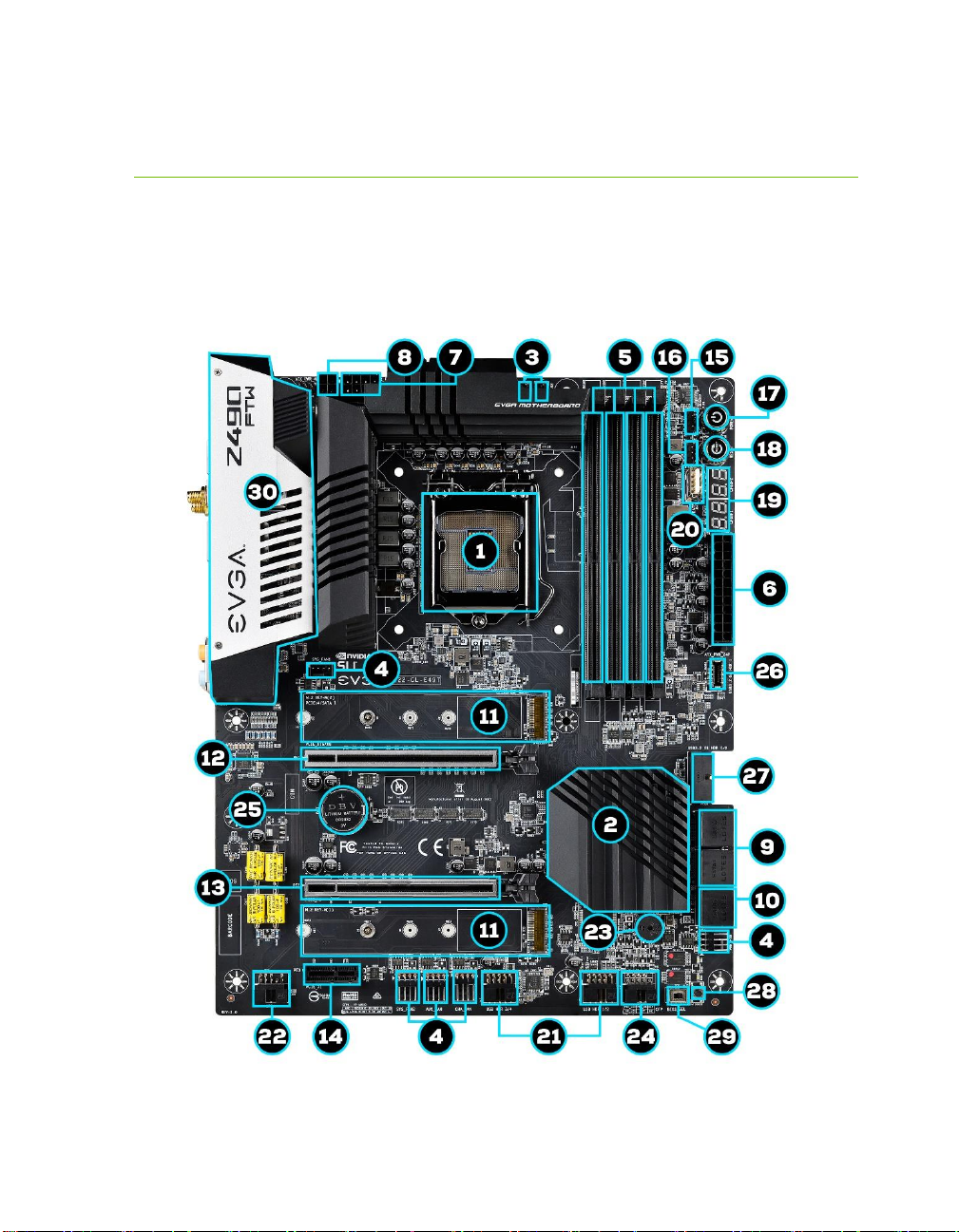
19. Debug POST Indicator / Hardware Monitor
This is a four-digit POST code reader, which displays in sets of 7-digit LED.
The display can be configured to show data in regular decimal format, or
hexadecimal, which means the characters available (when working as intended)
are 0-9, A-F and has a cap of 255 characters.
During POST, the left set of LEDs will display the various POST codes as they
cycle through the Power On Self-Test. The POST codes are listed in the
troubleshooting section on Page 155.
After the system boots, these same set of LEDs can be set to display a hardware
monitoring sensor, such as the CPU temperature in Celsius. This temperature
is specifically for the CPU socket, which will typically read slightly higher than a
given CPU core. To read this temp in Fahrenheit, take the value in Celsius,
multiply by 9/5 (or 1.8) and add 32.
The display can be used to show additional temperatures, or can be configured
in tandem with all 4 digits to provide live readings for voltages or temperatures.
For example, the LEDs can be configured to read voltages, such as 1.258 or -
55C for CPU temp for when you are using LN2 extreme cooling. Detailed
configuration instructions for the Debug Indicator are provided on Page 151.
20. USB to SPI for BIOS Flash
This USB Update Port is designed to connect directly to the motherboard to
allow the motherboard BIOS to be flashed, even if no CPU is installed. For
more information on how to flash your BIOS using this method, please see
Page 144.
21. USB 2.0 Headers
The USB2.0 header is used to connect additional USB interface plugs to the
motherboard; these headers are most often used to connect the motherboard to
the chassis to enable the USB2.0 ports on the chassis. These will function
similarly to the USB2.0 ports found on the motherboard’s hardwired I/O hub,
but these can also be used for the chassis’ front panel USB, auxiliary ports that
mount in the card slots, and certain devices that directly connect to the header.
USB 2.0 standard is 500ma @ 5V per port (header total is 1000ma) for
unpowered devices. If your USB device requires more power, it is
recommended to attach a powered USB Hub.

EVGA Z490 FTW (122-CL-E497)
- 19 -
22. Front Panel Audio Connector
This motherboard header is used to plug in the audio cable included with most
PC chassis. This connector is required for audio recording and/or playback
via the audio connectors on the chassis. This header has a connector that
looks similar to the USB2.0 header and uses the standard “HD Audio” jack.
Some chassis may provide two headers: one labeled HD Audio, and one
labeled AC’97 – an AC’97 cable is not compatible with this header on the
Z490 FTW.
23. PC Speaker
This is a small mono low-fidelity speaker, which is permanently attached to the
motherboard. Its primary use is for debugging purposes. A POST beep may
indicate a successful POST or various tones for USB initialization, while other
beeps may indicate an issue during the POST process. Please see Page 153 for
more details.
24. Front Panel Connectors
The Front Panel Connectors are the four main chassis connections. These
include the Power Switch, Power LED, Reset Switch, and HDD LED. The
Power and Reset switches are “Momentary Switches,” rather than “Latching
Switches,” which means the connection between two posts only needs a brief
moment to turn on the device, as opposed to requiring a constant connection.
For example, the Power and Reset switches can be triggered instantly with a
screwdriver by simultaneously touching the + and - posts.
The Power LED will power on with the system, indicating the system is on and
can blink in conjunction with CPU activity.
HDD LED will blink during access to the SATA ports; this is not activated for
M.2 SSDs.
25. CMOS Battery
The CMOS battery backup provides uninterruptable power to the BIOS/UEFI
to store all its settings; otherwise, each power on would act as if the BIOS was
just reset. These batteries typically last several years and rarely need to be
replaced.
26. USB 3.2 Gen2 Header (Type-C)
The USB 3.2 Gen2 header is used to connect additional USB interface plugs to
the motherboard; these headers are most often used to connect the
motherboard to the chassis to enable the USB 3.2 Gen2 ports on the chassis.
These will function similarly to the USB 3.2 Gen2 Type-C port sometimes

EVGA Z490 FTW (122-CL-E497)
- 20 -
found on a motherboard’s rear I/O hub, but can also be used for the chassis’
front panel USB, auxiliary ports that mount in the card slots, and certain
devices that directly connect to the header. The USB 3.2 Gen2 Header on the
Z490 FTW is a shielded USB 3.2 Gen2 Header and supports up to 10Gb/s
with USB 3.2 Gen2.
This USB 3.2 Gen2 Header has a power limit of 3000ma (3A) @ 5V.
27. USB 3.2 Gen1 Header
The USB 3.2 Gen1 header is used to connect additional USB interface plugs to
the motherboard; these headers are most often used to connect the
motherboard to the chassis to enable the USB 3.2 Gen1 ports on the chassis.
These will function similarly to the USB 3.2 Gen1 ports found on the
motherboard’s rear I/O hub, but can also be used for the chassis’ front panel
USB, auxiliary ports that mount in the card slots, and certain devices that
directly connect to the header.
USB 3.2 Gen1 standard is 900ma @ 5V for unpowered devices. If your USB
device requires more power, it is recommended to attach a powered USB Hub.
USB 3.2 Gen2 Type-A (found on the I/O Hub) shares the power limit of USB
3.2 Gen1 at 900ma @ 5V.
Note: USB 3.2 Gen1 is more commonly referred to as USB 3.0.
28. BIOS SafeBoot Button
Pressing this button while the system is running will reboot the motherboard
directly into the BIOS without clearing CMOS. This feature is very useful for
situations where the motherboard is unable to complete boot due to a failed
overclock and the user does not want to erase the previous settings used.
29. BIOS Selector Switch
This switch toggles between physical BIOS chips. This board has 2 BIOS chips
as a permanent fixture. Each chip holds only the settings and profiles that have
been saved to the BIOS chip while active. This allows you to swap between
two physically different BIOS chips. This also makes it substantially easier to
hotflash a BIOS if needed. If instructions are needed for hotflashing a BIOS,
please contact EVGA Customer Service (Page 150 for contact info).
30. Rear Panel Connectors (Figure 2)
This is the section referred to as the I/O Hub. This panel contains the
hardwired USB, Sound, and Ethernet connections. Please see Page 13 for a
component level breakdown.
Table of contents
Other EVGA Motherboard manuals

EVGA
EVGA NVIDIA nForce 650i Ultra User manual

EVGA
EVGA H55 User manual

EVGA
EVGA P67 SLI User manual

EVGA
EVGA Z77 Stinger User manual

EVGA
EVGA P67 SLI User manual

EVGA
EVGA 790i - nForce SLI FTW Motherboard User manual

EVGA
EVGA Z75 SLI User manual

EVGA
EVGA 123-CD-E635 User manual

EVGA
EVGA 730a - nForce Motherboard - ATX User manual

EVGA
EVGA X58 3X SLI User manual

EVGA
EVGA Z75 SLI User manual

EVGA
EVGA Z87 User manual

EVGA
EVGA 111-CD-E630-TR User manual

EVGA
EVGA H370 Stinger User manual

EVGA
EVGA 270-SE-W888-KR User manual

EVGA
EVGA P67 FTW Owner's manual

EVGA
EVGA Classified SR-X User manual

EVGA
EVGA P55V User manual

EVGA
EVGA X58 Classified3 User manual

EVGA
EVGA EVGA X79 DARK User manual