EVGA B360 Micro Gaming User manual

EVGA B360 Micro Gaming (112-CS-E365)
- 1 -
User Guide
EVGA B360 Micro Gaming
Specs and Initial Installation

EVGA B360 Micro Gaming (112-CS-E365)
- 2 -
Table of Contents
User Guide...............................................................................................................- 1 -
EVGA B360 Micro Gaming ......................................................................................- 1 -
Specs and Initial Installation.....................................................................................- 1 -
Before You Begin… .................................................................................................- 4 -
Parts NOT in the Kit............................................................................................................. - 5 -
Intentions of the Kit.............................................................................................................. - 5 -
Motherboard Specifications.................................................................................................. - 6 -
Unpacking and Parts Descriptions........................................................................................ - 8 -
EVGA B360 Micro Gaming Motherboard LED reference................................................... - 9 -
EVGA B360 Micro Gaming Motherboard Component Legend......................................... - 10 -
Component Legend Descriptions ....................................................................................... - 12 -
PCIe Slot Breakdown (Coffee Lake-S) .............................................................................. - 18 -
M.2 Slot Breakdown (Coffee Lake-S)................................................................................ - 18 -
Preparing the Motherboard....................................................................................- 19 -
Installing the CPU .............................................................................................................. - 19 -
Installing the CPU Cooling Device .................................................................................... - 20 -
Installing System Memory.................................................................................................. - 21 -
Installing the I/O Shield and I/O Cover.............................................................................. - 22 -
Installing the Motherboard......................................................................................- 22 -
Securing the Motherboard into a System Case................................................................... - 23 -
Installing M.2 devices.............................................................................................- 25 -
Installing M.2 Key-M Socket 3 Devices ............................................................................ - 25 -
Incorrect M.2 Installation Example: ................................................................................... - 26 -
Installing M.2 Key-E Socket 1 Devices.............................................................................. - 27 -
Tested CPU and Memory ................................................................................................... - 29 -

EVGA B360 Micro Gaming (112-CS-E365)
- 3 -
Tested M.2 Key-M ............................................................................................................. - 29 -
Tested M.2 Key-E............................................................................................................... - 30 -
Connecting Cables.............................................................................................................. - 31 -
First Boot................................................................................................................- 41 -
Memory Setup .................................................................................................................... - 41 -
HDD/SSD/M.2 Setup ......................................................................................................... - 42 -
M.2 SSD, PCIe SSD, and NVMe SSD Installation steps ................................................... - 43 -
Partitioning and Formatting a Drive .......................................................................- 45 -
Fan Header DC and PWM setup ...........................................................................- 50 -
Realtek HD Audio Manager ...................................................................................- 54 -
EVGA NU Audio.....................................................................................................- 72 -
The NU Audio Control Panel ............................................................................................. - 75 -
NU Audio Custom Settings:............................................................................................... - 83 -
Using the E-LEET X Software Suite ......................................................................- 85 -
Installing Drivers and Software ..............................................................................- 89 -
Windows 10 Driver Installation.......................................................................................... - 89 -
Warranty and Overclocking................................................................................................ - 91 -
Troubleshooting .....................................................................................................- 92 -
Flashing the BIOS .............................................................................................................. - 92 -
SSD / HDD is not detected................................................................................................. - 94 -
System does not turn on...................................................................................................... - 96 -
System turns on, but fails to successfully POST ................................................................ - 97 -
Have a question not covered above, or want some online resources? ................................ - 99 -
EVGA Glossary of Terms ................................................................................................ - 100 -
Compliance Information.......................................................................................- 103 -

EVGA B360 Micro Gaming (112-CS-E365)
- 4 -
Before You Begin…
The EVGA B360 Micro Gaming is the discerning gamer’s choice for building a
powerfully affordable system. This motherboard eliminates frills and unneeded
features, while still providing a solid platform capable of gaming, work, or study.
Featuring an 8-Phase PWM design, the B360 Micro Gaming supports the latest
Intel®Socket 1151 Coffee Lake-S 6-Core processors, and 2 DDR4 DIMMs that
support up to 32GB at 2667MHz. This motherboard also supports USB 2.0,
3.1 Gen1, and 3.1 Gen2 ports and headers to keep your devices connected, and
storage options including six SATA 6Gbps ports and an M.2 Key-M slot.
Stream your favorite content with an Intel®i219V Gigabit NIC and a CNVi-
ready M.2 Key-E slot. Make the EVGA B360 Micro Gaming your next
motherboard and enjoy modern performance and features for a budget-friendly
price.
Lastly, a motherboard is only as good as its BIOS, and the EVGA B360 Micro
Gaming features an updated UEFI/BIOS GUI with a focus on enthusiast
features and functionality in a lean, straight-forward package. You won’t need
to be an expert to configure your motherboard, but if you are, you’ll find
features unavailable anywhere else.
Combining the best of current technology with the latest innovations, EVGA is
further refining motherboard performance!

EVGA B360 Micro Gaming (112-CS-E365)
- 5 -
Parts NOT in the Kit
This kit contains all the hardware necessary to install and connect your new
EVGA B360 Micro Gaming Motherboard. However, it does NOT contain the
following items, which must be purchased separately in order to make the
system fully functional and install an Operating System:
Intel®Socket 1151 Processor
DDR4 System Memory
CPU Cooling Device
PCI Express Graphics Card
Power Supply
Hard Drive or SSD
Keyboard / Mouse
Monitor
Optical Drive (Optional)
EVGA assumes you have purchased all the necessary parts needed to allow for
proper system functionality. For a full list of supported CPUs on this
motherboard, please visit www.evga.com/support/motherboard
Intentions of the Kit
When replacing a different model motherboard in a PC case, you may need to
reinstall your operating system, even though the current HDD/SSD may
already have one installed. Keep in mind, however, you may sometimes also
need to reinstall your OS after a RMA even if your motherboard remains the
same due to issues that occurred prior to replacing the motherboard.

EVGA B360 Micro Gaming (112-CS-E365)
- 6 -
Motherboard Specifications
Size:
Micro-ATX form-factor of 8.0 inches x 9.6 inches (200mm x 244mm)
Microprocessor support:
Intel®Socket 1151 Processor (Coffee Lake-S)
Operating Systems:
Supports Windows 10 64bit
System Memory support:
Supports Dual-Channel DDR4 up to 2667MHz
Supports up to 32GB of DDR4 memory.
USB 2.0 Ports:
5x from Intel®B360 PCH –1x internal via 1 FP header
Supports transfer speeds up to 480 Mbps with full backwards compatibility
USB 3.1 Gen 1 Ports:
2x from Intel®B360 PCH –2x internal via 1 FP header
Supports transfer speeds up to 5Gbps with full backwards compatibility
USB 3.1 Gen 2 Ports:
4x from Intel®B360 PCH –4x external Type-A
Supports transfer speeds up to 10Gbps with full backwards compatibility
SATA Ports:
Intel®B360 PCH Controller
6x SATA 6.0 Gb/s (600 MB/s) data transfer rate
- Supports hot plug
Onboard Audio:
Realtek Audio (ALC888) + SV3H615 3D Headphone Amp
Supports 5.1 Channel HD Audio
Onboard LAN:
1x Intel®i219V Gigabit (10/100/1000) Ethernet PHY
Power Functions:
Supports ACPI (Advanced Configuration and Power Interface)
Supports S0 (normal), S3 (suspend to RAM), S4 (Suspend to disk - depends
on OS), and S5 (soft - off)

EVGA B360 Micro Gaming (112-CS-E365)
- 7 -
PCIe Expansion Slots:
1x PCIe x16 slot
1x PCIe x4 slot
1x PCIe x1 slot
PCIe 3.0 Support:
Low power consumption and power management features
Additional Expansion Slots:
1x M.2 Key-M 80mm slot PCIe/NVMe
1x M.2 Key-E CNVi-Ready slot for WiFi/BT*
Fan Headers:
3x 4-pin PWM controlled headers
ALL FAN HEADERS HAVE A MAXIMUM POWER LIMIT OF 1 AMP
@ 12 VOLTS (12 WATTS). EXCEEDING THIS LIMIT WILL CAUSE
IRREPARABLE DAMAGE TO THE BOARD.
*WiFi card/kit is not included and must be purchased separately.
EVGA B360 Micro Gaming (112-CS-E365)
- 8 -
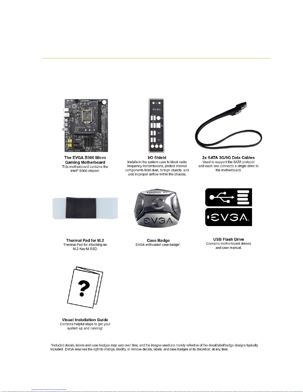
Unpacking and Parts Descriptions
The following accessories are included with the EVGA B360 Micro Gaming
Motherboard:

EVGA B360 Micro Gaming (112-CS-E365)
- 9 -
EVGA B360 Micro Gaming Motherboard LED reference
The EVGA B360 Micro Gaming Motherboard has one LED to indicate power and
connectivity. Below is the location of the LED and its function.
1. +5VSB
a. White: Voltage present (Does not mean PSU is outputting in-spec, only
that this specific voltage is detected)
1.
LED Legend
5VSB

EVGA B360 Micro Gaming (112-CS-E365)
- 10 -
EVGA B360 Micro Gaming Motherboard Component Legend
The EVGA B360 Micro Gaming Motherboard with the Intel®B360 Express Chipset.
Figure 1 shows the motherboard and Figure 2 shows the back panel connectors
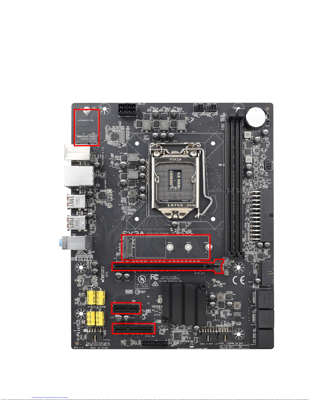
FIGURE 1. B360 Micro Gaming Motherboard Layout
**For a FULL description of the above legend, please see Page 12.
1. CPU Socket 1151 8. M.2 Socket 3 Key-M80mm 15. USB 3.1 Gen 1 Header
2. Intel B360 PCH (Southbridge) 9. M.2 Socket 3 Key-E32mm 16. Front Panel Audio Connector
3. PWM Fan Header (1 amp PWM) 10. PCI-ESlot x16 17. Intel Trusted Platform Module
4. DDR4 Memory DIMMSlots 1-4 11. PCI-ESlot x4 18. USB 2.0 Header
5. 24-pin ATX power connector 12. PCI-ESlot x1 19. Front Panel Connectors
6. 8 pin EPS Connector 13. Clear CMOS Jumper Posts 20. Rear Panel Connectors (Figure 2)
7. Intel Sata III 6Gb/s Ports 14. CMOS Battery
Component Legend
EVGA B360 Micro Gaming (112-CS-E365)
- 11 -
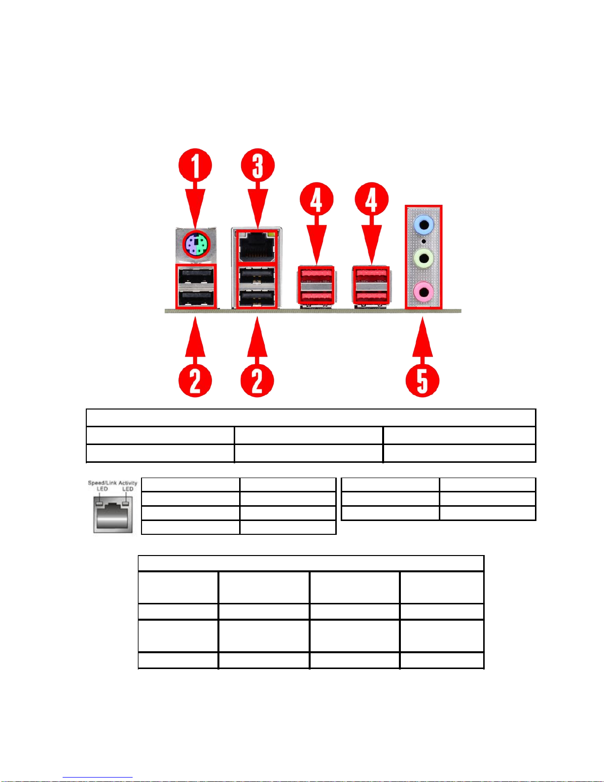
Figure 2. Chassis Rear Panel Connectors
1. PS/2 Keyboard / Mouse Port 3. Intel i219V Gigabit LAN 5. Analog Audio Jacks
2. USB 2.0 Port 4. USB3.1 Gen 2 (Type A)Port
I/O Hub
Speed/Link LED Status Description Activity LED Status Description
Orange 1000Mbps data rate Off No Data Transmission
Green 100 Mbps data rate Blinking (Green) Data Transmission
Off 10 Mbps data rate
Blue Line in Rear Speakers Out Side Speakers Out
Pink Mic In Mic In Center / Sub Out
2/2.1 Channel
4/4.1 Channel
5.1 Channel
Green
Front Speakers Out /
Front Speakers +Sub
Front Speakers Out /
Front Speakers +Sub
Front Speakers Out
Analog Audio
Port Breakdown
3.5mm Audio Jack Legend

EVGA B360 Micro Gaming (112-CS-E365)
- 12 -
Component Legend Descriptions
1. CPU Socket 1151
This is the interface for the Central Processing Unit (CPU), and supports Core™
Series i3, i5, and i7 models compatible with the Intel®LGA1151 Socket, based
on Coffee Lake-S architecture.
2. Intel®B360 PCH (Southbridge)
The Platform Controller Hub (PCH) handles the role that was previously held
by the South Bridge. On B360 motherboards, the CPU and PCH are directly
linked via DMI 3.0, which uses 4 lanes to provide transfer rates at up to 8 GT/s
per lane. From there, the PCH allocates bandwidth to smaller PCIe slots and
devices, such as M.2 Key-E, USB, audio, etc. In simplified terms, the PCH
works as a hub for peripherals that are less bandwidth-intensive.
3. PWM Fan Headers
4-pin fan headers that control the fan speed based on a configurable curve or
static percentage. PWM (Pulse-Width Modulation) works by pulsing power to
the fan at a constant rate and sending the RPM signal to the fan’s controller via
a Sense cable, rather than adjusting fan speed by increasing and decreasing
voltage. This method is preferable because it eliminates voltage-based fan stall
points. Please see Page 50 for more in-depth PWM breakdown and PWM
controls within BIOS/UEFI.
4. DDR4 Memory Slots
The memory slots support up to two 288-pin DDR4 DIMMs in Dual-Channel
mode with Coffee Lake-S processors.
Coffee Lake-S processors are certified for Dual-Channel mode, and will be
enabled only upon using two sticks of supported memory, according to the
installation guide on Page 21. Coffee Lake-S supports up to 32GB (2x16GB)
on the B360 chipset, and up to 2667MHz. 32GB and larger RDIMM modules
are *NOT* supported on this platform.
Using 1 DIMM may significantly lower performance depending on the
application; for best use, use a two stick kit of RAM, subject to your CPU’s
limitations noted above.
The speeds listed above cannot be guaranteed because Intel®only certifies the
speed of the memory controller up to 2667MHz Coffee Lake-S platforms and
all speeds above Intel®’s certified speeds require overclocking, including XMP
automatic operation.

EVGA B360 Micro Gaming (112-CS-E365)
- 13 -
5. 24-pin ATX power connector
The main power for the motherboard is located on the right side of the board
and parallel to the PCB; this is also described as a “right-angle” connector (See
Page 32 for more specifics to the connector itself, and associated wiring /
pinouts). The 24-pin connector is directional and the connector needs the tab
on the socket to line up with the release clip located on the 24-pin connector
from the power supply. This connector pulls the bulk of the power for all
components.
6. 8-pin EPS Connector
The +12V EPS is the dedicated power input for the CPU (See Page 33 for more
specifics to the connector itself, and associated wiring / pinouts). Carefully
choose the correct power cable by consulting with the installation manual for
your power supply. This connector is designed to only work with an EPS or
CPU cable. System builders sometimes make the mistake of plugging in a PCIe
8-pin or 6+2-pin connector, which will prevent the board from POSTing and
possibly short or damage the board. Although the cables appear similar, they
are wired differently and attaching a PCIe cable to an EPS connector may cause
damage to the motherboard.
If no power cable is connected or detected, the system will not POST.
7. Intel®SATA 6Gbit/s Ports
The Intel®B360 PCH has a 6-port SATA III 6 Gb/s controller (See Page 40
for specifics on the connectors). This controller is backwards compatible with
SATA and SATA II devices, and supports SSDs, HDDs and various types of
optical devices (CDROM, DVDROM, BD-ROM, etc). The controller also
supports NCQ, TRIM, and hot swap capability (provided the proper
HDD/SSD bays/racks are installed).
8. M.2 Socket 3 Key-M 80mm
M.2 is an SSD standard, which uses up to four PCIe lanes and utilizes Gen3
speeds. Most popularly paired with NVMe SSDs, this standard offers
substantially faster transfer speeds and seek time than SATA interface
standards. All M.2 devices are designed to connect via a card-bus style
connector and be bolted into place and powered by the connector, rather than
by a dedicated data cable and power cable.
This socket will support Key-M devices of 80mm length.
This connector can utilize PCIe and NVMe-based M.2 SSDs.

EVGA B360 Micro Gaming (112-CS-E365)
- 14 -
9. M.2 Socket 1 Key-E 32mm
M.2 Key-E sockets are generally used for WiFi and Bluetooth cards. Key-E and
Key-M connectors are different, meaning that devices are not interchangeable
between sockets. This socket is CNVi-Ready.
10. PCIe Slot x16*
PCIe x16 slots are primarily used for video cards. These full-length slots will
provide 8 or 16 lanes of bandwidth to a full-size card, and are backwards-
compatible with x8, x4, and x1-length cards.
Coffee Lake-S Socket LGA1151 processors have 16 PCIe lanes available for
routing.
11. PCIe Slot x4*
PCIe x4 slot PE3 uses up to 4 Gen 3 lanes from the PCH. This slot is typically
used for sound cards, WiFi, USB, LAN or other peripheral cards.
Using this slot will have no effect on the bandwidth or throughput of PE1
because this slot uses only PCH bandwidth.
12. PCIe Slot x1
PCIe x1 is the smallest form-factor PCIe card slot. They are all one lane and
are used for low-bandwidth products.
13. Clear CMOS Jumper Posts
The motherboard uses CMOS RAM to store set parameters. Clear CMOS by
bridging the two posts with a jumper or metallic object, such as a screwdriver.
This feature has two main uses: The first is to clear BIOS and power on before
updating the BIOS, and the second is to troubleshoot when the motherboard
fails to POST (e.g. after upgrading RAM or CPU, adding new hardware, a failed
overclock, etc.). These posts provide a much faster means of resetting CMOS
than removing the CMOS battery and discharging power to the board.
14. CMOS Battery
The +3V CMOS battery backup provides uninterruptable power to the
BIOS/UEFI to keep all of the settings; otherwise, each boot would behave like
you just reset the BIOS. These batteries typically last several years and rarely
need to be replaced.
15. USB 3.1 Gen 1 Header
The USB 3.1 Gen 1 headers are used to connect additional USB interface plugs
to the motherboard; these headers are most often used to connect the

EVGA B360 Micro Gaming (112-CS-E365)
- 15 -
motherboard to the chassis to enable the USB 3.1 Gen 1 ports on the chassis.
These function the same as the USB 3.1 Gen 1 ports found on the
motherboard’s hardwired I/O hub, but the Header can be used to attach front
panel USB, auxiliary ports that mount in the card slots, and also some devices
that directly connect to the header.
USB 3.1 Gen 1 standard available current is 900mA @ 5V for unpowered
devices. If your USB device requires more power than this, it is recommended
to attach a powered USB Hub.
USB 3.1 Gen 2 Type-A (found on the I/O Hub) shares the power limit of USB
3.1 Gen 1 at 900mA @ 5V.
16. Front Panel Audio Connector
This is a motherboard header to plug in the audio cable originating from most
PC chassis, allowing audio to be recorded from or played through the audio
connectors on the chassis. This header has a connector that looks similar to
USB2 and will use the standard “HD Audio” jack. Some systems may have two
headers: one labeled HD Audio, and one labeled AC’97 – this header is not
compatible with AC’97.
This header is designed to be used with speakers and headphones connected to
the front panel audio out. When headphones or speakers are plugged in to the
front panel audio, the EVGA NU Audio becomes available for additional audio
options instead of the Realtek Audio Controller.
17. Trusted Platform Module (TPM) Header
TPM is an international standard for utilizing hardware and software to prevent
hardware and software tampering from external sources. TPM is commonly
used for BitLocker disk encryption, for example. The EVGA B360 Micro
Gaming features a TPM header, which allows for the user to add a TPM
module for individual security needs.
The TPM module is not included with this motherboard and must be purchased
separately. The TPM Header is not compatible with Intel TPM.
18. USB 2.0 Headers
The USB 2.0 headers are used to connect additional USB interface plugs to the
motherboard; these headers are most often used to connect the motherboard to
the chassis to enable the USB 2.0 ports on the chassis. These will function the
same as the USB 2.0 ports found on the motherboard’s hardwired I/O hub, but
these can be used to attach to front panel USB, auxiliary ports that mount in the
card slots, and also some devices that directly connect to the header.

EVGA B360 Micro Gaming (112-CS-E365)
- 16 -
USB 2.0 standard is 500mA @ 5V per port (header total is 1000mA) for
unpowered devices. If your USB device requires more power than this, it is
recommended to attach a powered USB Hub.
19. Front Panel Connectors
The Front panel connectors are the four main chassis connections. These
include the Power Switch, Power LED, Reset Switch, and HDD LED. The
Power and Reset switches are both designed to use “Momentary Switches,”
rather than “Latching Switches,” which means the connection between the two
posts needs to be made just briefly for it to work, as opposed to being held in
place. This is why the Power and Reset switches can be triggered with a screw
driver by simultaneously touching the + and - posts.
Power LED will power on with the system, indicating the system is on and can
blink with CPU activity.
HDD LED will blink during access to the SATA ports. M.2 SSDs will also
activate this LED.
20. Rear Panel Connectors (Figure 2)
This is the section referred to as the I/O Hub. This panel contains the
hardwired USB, Sound, and Ethernet connections. Please see Page 11 for a
component level breakdown.
* There are two numeric references for PCIe: one is mechanical, which is the actual slot-
length footprint, and the second is electrical, which is a reference of how many PCIe
lanes are routed to the slot.
Because PCI Express is designed to be a universal architecture, you can install x1 cards,
such as sound cards or USB controllers into an x16 slot. Many types of cards can use
different amounts of PCIe lanes, while some applications use only certain parts of a
card, such as compute apps that allow a card to run off a single PCIe lane. This is why
there are x16 mechanical slots with an x1 electrical PCIe lane. Using the entire length of
a PCIe slot is unnecessary, nor does it cause an adverse effect to use a shorter form-
factor bus card in a slot that physically can hold a larger form-factor bus card.
EVGA B360 Micro Gaming (112-CS-E365)
- 17 -
Card Slots
The B360 Micro Gaming features one x16 PCIe slot, one x4 PCIe slot, one x1 PCIe
slot, one Socket 3 Key-M M.2 80mm (backwards compatible with Key-M 60mm,
and 42mm devices), and one horizontal Socket 1 Key-E M.2.

EVGA B360 Micro Gaming (112-CS-E365)
- 18 -
PCIe Slot Breakdown (Coffee Lake-S)
PCIe Lane Distribution (Core™i3, i5, and i7
16-Lane Processors)
PE1 –x16 (Gen3, x16 lanes from CPU)
PE2 –x1 (Gen3, x1 Gen3 lanes from PCH
PE3 –x4 (Gen3, x4 Gen3 lanes from PCH
M.2 Slot Breakdown (Coffee Lake-S)
PCIe Lane Distribution (Core™i3, i5, and i7
16-Lane Processors)
M.2 Key-M (80mm) –x4 PCIe Gen 3 lanes PCH.
M.2 Key-E (32mm) –x1 PCH lane
EVGA B360 Micro Gaming (112-CS-E365)
- 19 -
Preparing the Motherboard
Installing the CPU
Note: EVGA strongly recommends that you completely disconnect AC power from
your power supply prior to changing your CPU. This ensures the
motherboard will use the correct startup procedure for all onboard devices. If
AC power is not disconnected, the replacement is still supported, but may
require additional reboots to boot successfully.
Be very careful when handling the CPU. Hold the processor only by the edges and do
not touch the bottom of the processor.
Note: Use extreme caution when working with the
CPU to avoid damaging the pins in the
motherboard’s CPU socket!
Do not remove the socket cover until you have
installed the CPU. This installation guide was
created without using a socket cover to better
illustrate the CPU Socket area. However,
users should remove the cover as the last
step, not the first step.
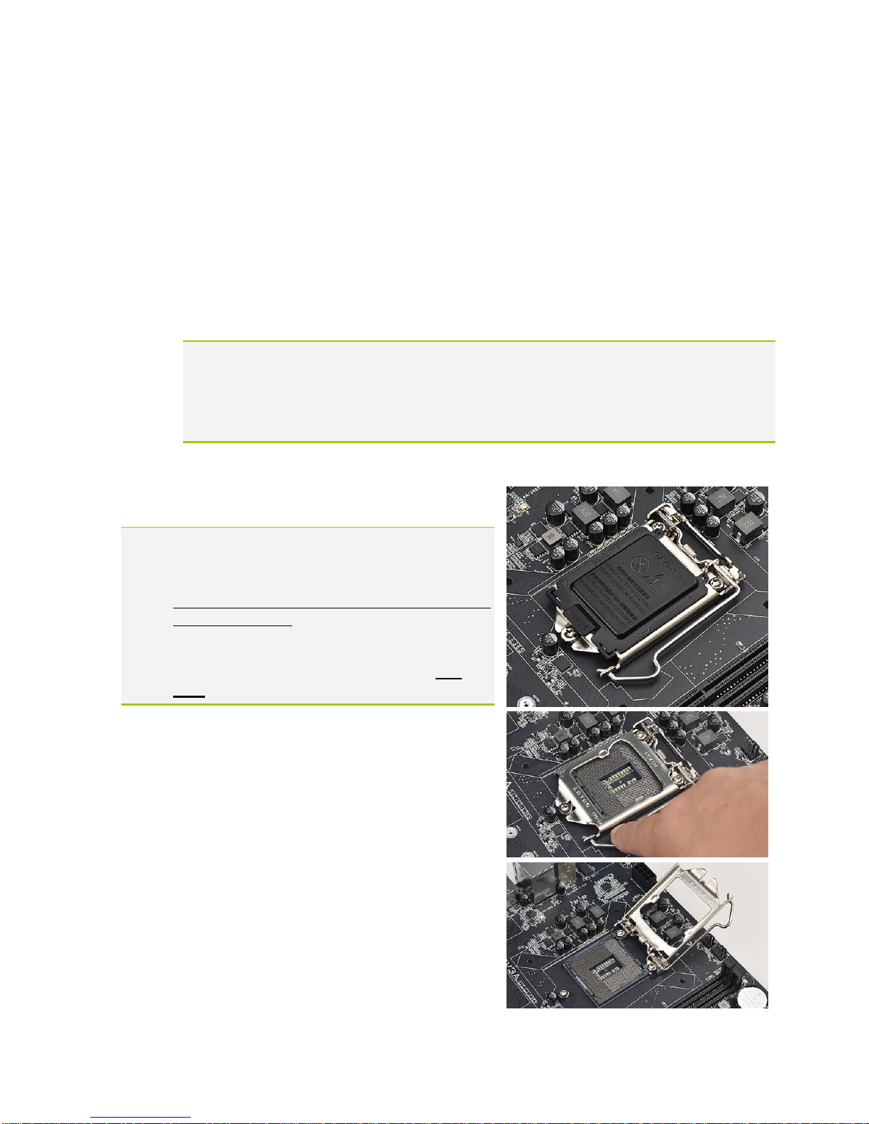
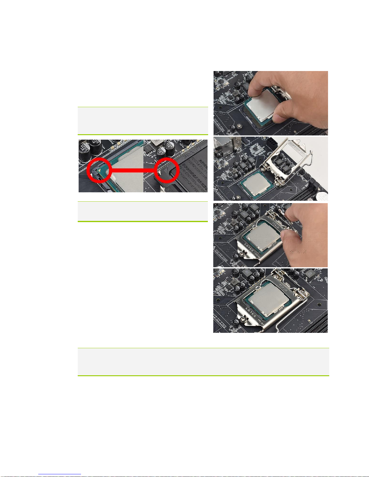
Use the following procedure to install the CPU
onto the motherboard.
1. Unhook the socket lever by pushing
down and towards the socket.
2. Pull the socket lever back and gently lift
the load plate to open the socket. Make
sure to avoid touching or dropping items
into the socket; otherwise, you may
damage the board socket and/or CPU
pins, which may void your warranty.
EVGA B360 Micro Gaming (112-CS-E365)
- 20 -
3. Align the notches on the CPU to the
notches in the socket, and lower the
processor straight down into the socket.
Note: The gold triangle key on the CPU
should match the triangle key on
the load plate.
Note: Make sure the CPU is fully seated
and level in the socket.
4. Lower the load plate so that it is resting
on the CPU.
5. Carefully lock the lever back into place
by lowering it down to the hook, then
push the lever towards the socket and
down under the hook.
6. Remove the plastic protective socket
cover by pulling it straight up and away
from the socket.
Note: After removing the CPU socket cover, it is recommended to store it in case
you ever need to transport your motherboard. If you ever remove the CPU, it
is highly recommended to reinstall the socket cover.
Installing the CPU Cooling Device
There are many different cooling devices that can be used with this
motherboard. Follow the instructions that come with your cooling assembly.
Table of contents
Other EVGA Motherboard manuals

EVGA
EVGA SR-3 DARK User manual

EVGA
EVGA X58 SLI LE User manual

EVGA
EVGA Z370 Classified K User manual

EVGA
EVGA P67 SLI User manual

EVGA
EVGA H370 Stinger User manual

EVGA
EVGA P67 FTW User manual

EVGA
EVGA nForce 750i SLI User manual

EVGA
EVGA X58 Classified Installation guide

EVGA
EVGA 790i - nForce SLI FTW Motherboard User manual

EVGA
EVGA 132-CK-NF79-A1 User manual

EVGA
EVGA X570 FTW Reference manual

EVGA
EVGA nForce 750i User manual

EVGA
EVGA X299 Micro User manual

EVGA
EVGA 120-LF-E650-TR User manual

EVGA
EVGA nForce 780i SLI FTW User manual

EVGA
EVGA nForce 4 User manual

EVGA
EVGA X58 SLI3 User manual

EVGA
EVGA 132-GT-E768 User manual

EVGA
EVGA Z87 User manual

EVGA
EVGA nForce 123-YW-E175 User manual


