Evil Mad Bulbdial User manual

Kit versions 1.0-1.1
Manual v. 1.1a
Support: http://www.evilmadscientist.com/forum/
Distributed by
Evil Mad Science LLC
http://evilmadscience.com/
LED Shadow Clock Kit
Assembly Guide
An open-source hardware+software project. For design files, source code, & additional
documentation, please visit: http://wiki.evilmadscience.com/Bulbdial
The Bulbdial Clock kit is based on an original design concept by David
Friedman of IronicSans.com and developed at Evil Mad Scientist Laboratories.
The Bulbdial Clock works like an indoor sundial. Three rings of LEDs cast
shadows of different lengths, forming three moving hands on the clock face.
This guide covers the procedures for assembling the Bulbdial Clock and its
accessories. Please exercise appropriate safety practice while soldering.

STEP 0: Tool Checklist
Essential tools: Needed to build the kit:
1. Soldering iron + solder
Suggested, but not required
Small nippers for for clipping loose wire ends close to
the circuit board.
e.g., Sears Craftsman
A basic soldering iron meant for electronics, with a reasonably
fine point tip. We recommend one of this design-- a "pencil
shape" soldering iron (not gun!) with a base that holds the iron
and a wet sponge. A tip in good condition (a “tinned” tip)
should get shiny when hot-- able to melt and wet to solder.
While you don’t need an expensive one, the iron can make a
big difference in the time needed to build the kit. (Seriously. If
you use one that is old and busted, or a $10 radio shack iron,
or that thing from the dollar store, you should expect to spend
at least twice as long soldering!)
Our recommendation for a low-cost iron:
model WLC100 by Weller, about $40.
[Bulbdial Assembly Guide]
2. Angle flush cutters
3. Electrical power
You’ll also need some solder. Thin rosin-core solder (roughly
.020 - .040” in diameter) is the most common type for
electronic soldering, and is the only choice that is appropriate
for electronic kits. Either standard (lead-bearing) or newer
“lead free” solder types will both work just fine.
And for the adventurous...
1. USB-TTL Cable
FTDI model TTL-232R or equivalent. A “smart” converter
cable with a USB interface chip inside. One end hooks up to
your USB port, the other to the clock. This allows you to
program the Bulbdial Clock through the Arduino development
environment ( http://arduino.cc/ ).
Besides programming, the cable can also be used to set the
time on the Bulbdial clock through a serial sync program.
The 5V version of the cable (TTL-232R-5V) can be used to
provide USB power to the Bulbdial clock.
2. Computer, Internet access, USB port....
All of the software and source code that you’ll need to reprogram
the clock is available online for free. You’ll need a reasonably recent
vintage computer (Mac, Windows, or Linux) and internet access.
Additional information is available at the project page:
http://www.evilmadscientist.com/go/BulbDialKit
2. Resistor lead forming tool
Allows fast, neat bending of resistor leads. Not many
parts like this in the Bulbdial kit, but if you’re obsessive....
The Bulbdial Clock kit comes with a regulated universal-input power supply that
accepts worldwide voltages and puts out 5 V at up to 150 mA. If you’re using your
own external power, make sure that it’s regulated, provides 4.5 to 5 V DC, and is
rated for at least 100 mA. (3 “AAA” cells can do the job, for example.) Please be
careful: Inappropriate voltage or polarity can cause permanent damage.
(International users may need to supply a plug adapter to fit the prongs into local
outlets.)
1. Small pliers with smooth jaws
Very helpful for final LED alignment. The jaws should be
smooth so that you don’t scratch the LEDs. Needlenose pliers
with masking tape over the jaws can be a good solution.
[2]

[Bulbdial Assembly Guide] [3]
Your kit came with a bill of materials: an up-to-date list of what’s in your
particular kit. The exact items may differ between versions of the kit,
for example between RGB and monochrome options.
In the instructions, we refer to components by their line
item number on the bill of materials. For example, #14
is the ATmega168 microcontroller.
In some places, the assembly procedure differs
between kit versions.
In particular, watch out for RGB ONLY or MONO ONLY
instructions, which are specific to the 3-color or
monochrome versions of the kit. If you aren’t sure
which you have, please consult your BOM.
STEP 1: It’s the BOM.

STEP 2: The Plan
[Bulbdial Assembly Guide] [4]
In the first part of the build,
we’ll be placing various
electronic components on
the large blue circuit board.
In the second half, we’ll be building up and
aligning the three rings of LEDs. The first ring is
on the main board, and the other two rings
have their own (red and green) circuit boards.

If they are taped together,
pull the tape straight off.
A zerohm jumper looks like a
resistor with one black stripe. Take one and bend it, like so.
Now, find location JP1. Insert the jumper there... ... and press it flush to the board.
(Next... Soldering!)
STEP 3: Placing the first component
[Bulbdial Assembly Guide] [5]
Our first component is a “zerohm” jumper, #4.
It goes in location JP1 on the main circuit board.
(And for this first one, we’ll take it slowly.)

[Bulbdial Assembly Guide] [6]
(3) Solder!
(4) Clip!
(1) Insert! (2) Bend!
45°, max
(0). Pre-form the leads of components if needed.
(For example, like the jumper in step 3.)
(1). Insert each component into the circuit board, from
the top, at its given location. Push it flush to the board
(Note that some components, like the chip and LEDs,
need to be inserted with a particular orientation.)
(2). If your component has flexible leads, gently bend the leads
out, up to 45°, to hold it in place while you solder.
(3). One at a time, from the back side, solder the leads of
the component to the circuit board.
(4). If the component has long and/or or flexible leads, clip off
the extra length, close to the board. (But not so close that
you’re clipping the board itself.)
• Your tip needs to be shiny (tinned). If not, melt some fresh
solder against it and quickly swipe clean on a wet sponge.
• Place the solder against the joint that you wish to connect.
• Touch the iron to the solder and joint for about one second.
Count it out: “one thousand one.”
• The solder should melt to the joint and leave a shiny
wet-looking joint. If not, let it cool and try again.
STEP 4a: Some hints on soldering
Adding components to the circuit board
As the old Heathkit manuals say, “it is interesting to note” that
the vast majority of problems reported with soldering kits turn
out to be due to unreliable solder connections.
Before we go further, here’s a quick refresher, with our
suggested procedures for adding components to the circuit
board. These procedures apply to most components in the kit.
TO BE CONTINUED...

We’ve already inserted the
jumper at location JP1.
Now bend out the leads to hold the
jumper in place while we solder Flip the board over and get ready to solder.
Solder both pins to the board. Inspect the solder joints; make sure
that they look shiny and wet. Clip the excess leads short.
[Bulbdial Assembly Guide] [7]
(Where we perform those
steps that we just described.)
Bend!
STEP 4b: Soldering that first component

Part #5 is a 10k resistor.
It’s the one small resistor, and it has stripes
of color brown-black-orange-gold.
Install it in location R11.
#5
#7 (RGB kit only-- see note above)
If you have the RGB kit:
If you have the monochrome (all white) kit:
[Bulbdial Assembly Guide]
[8]
Now that we’ve stepped through the
basics, we can proceed at a faster pace.
Resistors are added to the board in
the same way as the zerohm jumper,
and are not sensitive to orientation.
Part #7 is a 68 ohm resistor (color code blue-gray-
black-gold). It’s the one “normal size” resistor that looks
different from all the others. Install it in location R10.
Go on to Step 6, leaving R10 empty for the moment.
STEP 5: One or two resistors...

[Bulbdial Assembly Guide]
[9]
#6
If you have the mono kit: Install one more 24-ohm
resistor (#6) at location R10.
If you have the RGB kit: There should already be a
68-ohm resistor installed at R10, as shown here.
STEP 6: The rest of the resistors
The last resistor type is part #6, a 24 ohm
resistor (color code red-yellow-black-gold).
Install nine of these in locations R1 - R9.
Those resistors are located in the three
highlighted locations. Don’t forget R8!
[Bulbdial Assembly Guide]
[10]
#8
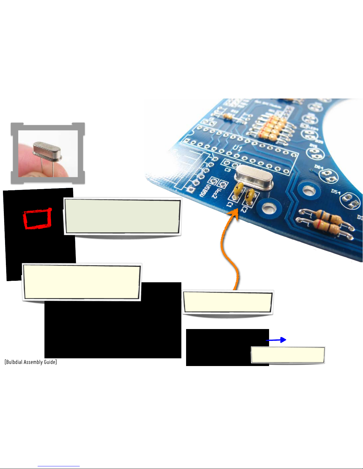
Install part #8, a 16 MHz quartz crystal. Its
two pins go in the outer two holes of the
location marked “Quartz.” Solder both pins
in place, much like a resistor.
Parts #9 are 18 pF ceramic capacitors-- little
yellow beads with two pins. There are two
similar types of ceramic capacitors in the kit,
so these ones are marked with a black stripe.
If they are taped together, pull
them straight out of the tape.
Solder these two capacitors on
the board at locations C1 and C2.
STEP 7: Crystal & Caps

Install two of them, at locations C3 and C6.
[Bulbdial Assembly Guide]
[11]
STEP 8: Two more caps
Parts #13 are 0.1 µF ceramic capacitors that
look almost the same as the 18 pF caps.
(These ones don’t have the black stripe.)
(C6)

Part #11 is a 6-pin header
that goes at location J2.
Set the circuit board atop the other two,
to raise it a bit above your work surface.
Place the header in its location;
it should sit flat as shown.
If you do not plan to connect to a computer, you can skip this step.
From the top, solder one pin of
the header to tack it in place.
Here’s how it looks with
one pin tacked in place.
Solder the other five pins on the bottom,
and then finish up the first one. The leads
do not need trimming.
[Bulbdial Assembly Guide] [12]
STEP 9: The USB-TTL connector In this step, we add a header that allows the Bulbdial clock to
be connected to a computer through an FTDI USB-TTL cable.
[Bulbdial Assembly Guide] [13]
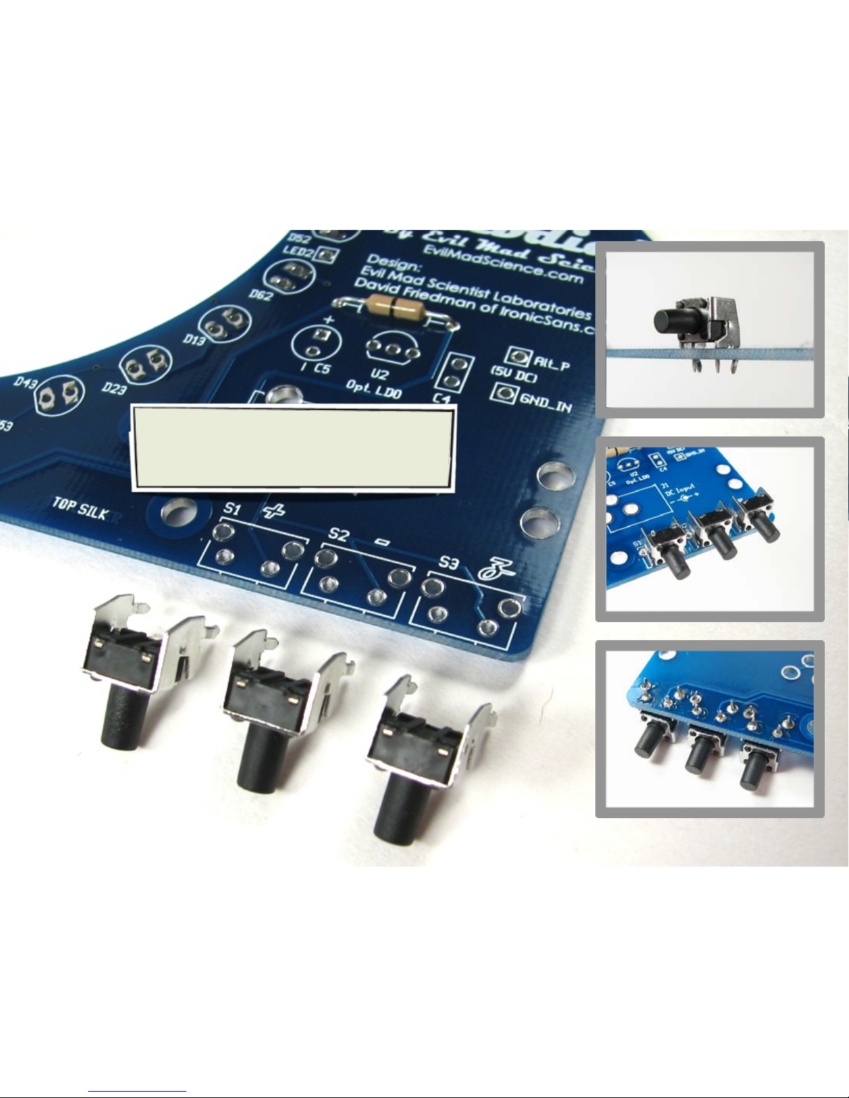
STEP 10: Buttons!
Parts #10 are right-angle tactile button switches.
“Snap” them into locations S1, S2 and S3, and make
sure that they sit flat on the board. Solder all four
pins of each switch.
[Bulbdial Assembly Guide] [14]
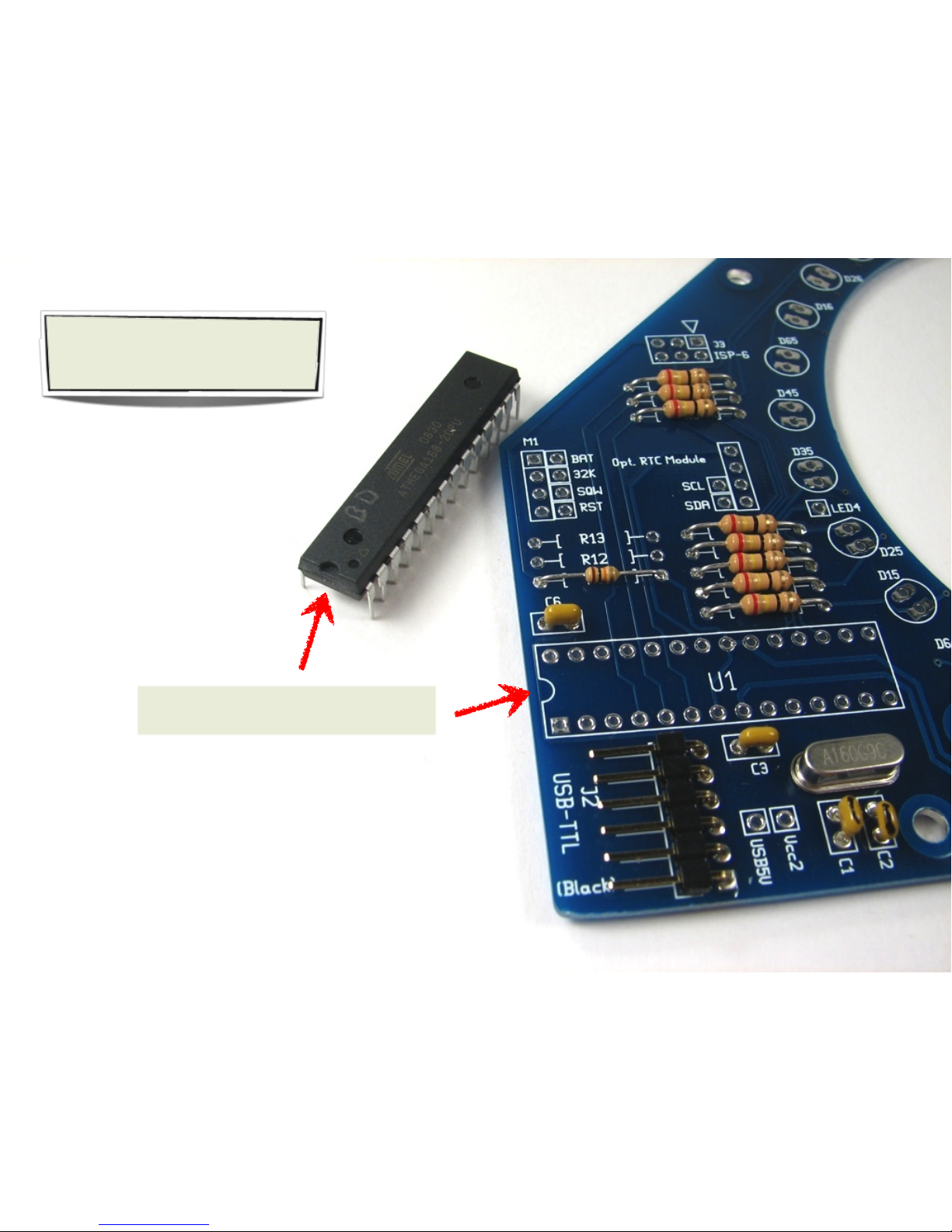
STEP 11a: AVR Microcontroller
Part #14 is an ATmega168, a type of
AVR microcontroller. It goes in location
U1, and must be oriented correctly.
First, identify the end of both the chip and of
location U1 that have the half-moon shape.
TO BE CONTINUED...

The chip should easily slip into the board. If
necessary, bend the pins of the chip to straight
up and down before inserting the chip. Do not
bend them by hand; bend all pins on one side at a
time by pushing them against a hard flat surface.
From end of chip:
YES!
no.
[Bulbdial Assembly Guide] [15]
STEP 11b: AVR Microcontroller, continued
Now place the chip in its location, matching
the marks on the chip and circuit board.
To hold the chip in place while you solder
it, you can bend out the corner pins, again
by up to 45°.
Solder every pin of the chip. Remember
to keep the soldering time per pin brief.
The pins do not need to be clipped.

The DC power jack, #15, goes in location
J1, matching the outline on the board.
Set the circuit board atop the other two,
to raise it a bit above your work surface,
as in step 9. Place the jack in its location.
From around back, it is possible to solder
one pin of the jack to tack it in place.
Solder one pin of the connector to tack
it in place. The larger metal here takes
a while to heat, up to about 8 s.
Here’s the view from the bottom side
after tacking the jack in place. Solder
the other two holes as well.
[Bulbdial Assembly Guide] [16]
STEP 12: Power jack
All three holes are now soldered. It is
not necessary to completely fill the
holes with solder.

Parts #12 are 4-pin
female headers that
go at location M1.
There are actually two locations at M1,
the headers go in the outer positions.
Put the headers in their places. Turn the board upside down to
rest flat on the headers. To verify that they are sitting flat, it may
be helpful to rest it on top of a pedestal, such as the kit box.
If you do not plan to use an RTC module, you can skip this step.
Solder one pin of each header
to tack them in place.
[Bulbdial Assembly Guide] [17]
STEP 13: RTC Sockets In this step, we add the sockets that allows the Bulbdial clock
to be connected to a real-time clock module (e.g., Chronodot)
With only one pin soldered, the headers are somewhat
“hinged”-- do your best to straighten both of them. Finally, solder the remaining
three pins of each header.
Straighten!

This completes the first part
of the build. We now move
on to putting the LEDs on
board. This is a 3D, multi-
board circuit, and we’ll test
each part individually as we
go, just to make sure that
everything works in the end.
[Bulbdial Assembly Guide] [18]

The LED bending jig is part #17.
To follow along, grab an LED from
your bag of blue LEDs, #16A. *
Use your thumb to hold
the LED body in place.
[Bulbdial Assembly Guide]
Each LED has a long and short lead. Place
an LED in the jig, being careful to put the
short lead on the side labeled “SHORT.”
Use your other thumb, or a firm surface, to
bend the leads firmly around the corner.
The LED, bent with the guide, with its 90°
turn intact. Your LEDs should look like this.
Executed properly, the LED should have a
sharp, right-angle bend and not spring out.
[19]
STEP 14: The LED bending guide Properly aligning the LEDs to make good shadows is an
important part of the assembly process. We use several
tools, including this LED guide, to ease this process along.
long lead
short lead
(*For monochrome kits, just grab any one of your LEDs, #16.)
[If you do not have an LED guide,
bend the LEDs 5.4 mm from their
base, in the direction shown.]

[Bulbdial Assembly Guide] [20]
STEP 15: Get ready to build the “blue” ring.
The circuit board we’ve
built up thus far
7/8” hex standoffs, #19
Hex wrench, #23
Long 4-40 screws, #24
3/8” hex standoffs, #18
“Red” circuit board, #3
Before starting to put the first ring of LEDs together,
gather up the necessary materials and have them at
the ready. You’ll also need to bend the first 30 LEDs
to shape. We’ll be using this setup to locate the LEDs
in place before soldering them.
30 Blue LEDs #16A*,
pre-formed, as in step 14.
(*Again, for monochrome kits, just grab 30 LEDs, #16.)
Table of contents


