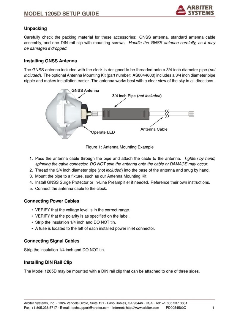
Arbiter Systems 1094B Installation manual

MODEL 1094B
GPS SUBSTATION CLOCK
OPERATION MANUAL
ARBITER SYSTEMS, INC.
PASO ROBLES, CA 93446
U.S.A.
WWW.ARBITER.COM

ii
Description
This manual is issued for reference only, at the convenience of Arbiter Systems. Reasonable effort
was made to verify that all contents were accurate as of the time of publication. Check with Arbiter
Systems at the address below for any revisions made since the original date of publication.
Contact Information
Arbiter Systems, Inc.
1324 Vendels Circle, Suite 121
Paso Robles, CA 93446
USA
(805) 237-3831
Website: www.arbiter.com
mailto:techsupp[email protected]
mailto:[email protected]
What This Manual Covers
This manual describes the set up and operation of the Model 1094B GPS Substation Clock.
Firmware Dates
This version of the manual is written for clocks having firmware dates of 5 December 2011 or later.
Any changes made in subsequent revisions which affect operation or specifications will be noted with
either (a) a new manual or (b) a revised version of this manual. To display the firmware version or
date for your instrument using the 1094 Utility application, see Section 6.6.10. The firmware version
may also be viewed using “VE” command in a terminal window; see Section 10.3.15, Miscellaneous
Commands in Chapter 10.
Firmware Updates
Firmware updates are available to customers by download from the Arbiter Systems website. Go
to www.arbiter.com and select Software Downloads under the Site Navigation (on the left). Then,
scroll down to Timing Software and select Model 1094B Software. For service, contact our factory
at Contact Information listed above. Electronic versions of this manual are also available on the
Arbiter website under Site Navigation, PDF Manuals and Datasheets.

iii
LIMITED WARRANTY
Arbiter Systems makes no warranty, expressed or implied, on any product manufactured or sold
by Arbiter Systems except for the following limited warranty against defects in materials and
workmanship on products manufactured by Arbiter Systems.
Clock products manufactured by Arbiter Systems are guaranteed against defective materials and
workmanship under normal use and service from the date of delivery for the period listed as
Limited Lifetime.1The responsibility of Arbiter Systems under this warranty is limited to repair
or replacement, at Arbiter Systems’ option, of any product found to be defective. Arbiter Systems
shall have no liability under this warranty unless it receives written notice of any claimed defect.
For warranty service or repair, products must be returned to a service facility designated by Arbiter
Systems. Buyer shall prepay all shipping charges to Arbiter Systems, and Arbiter Systems shall pay
shipping charges incurred in returning the product to Buyer. However, Buyer shall pay all shipping
charges, duties and taxes for products returned to Buyer in a country other than the United States
of America.
THE WARRANTY SET FORTH HEREIN CONSTITUTES THE ONLY WARRANTY OBLIGA-
TIONS OF ARBITER SYSTEMS, EXPRESSED OR IMPLIED, STATUTORY, BY OPERATION
OF LAW, OR OTHERWISE. ARBITER SYSTEMS DISCLAIMS ANY WARRANTY OF MER-
CHANTABILITY OR FITNESS FOR A PARTICULAR PURPOSE, AND BUYER EXPRESSLY
WAIVES ALL OTHER WARRANTIES.
This limited warranty does not extend to any product, which has been subject to
1. Improper use or application, abuse, or operation beyond its rated capacity, or contrary to the
instructions in the operation and maintenance manuals (if any);
2. Accident;
3. Repair or maintenance performed by Buyer, except in accordance with the operation and
maintenance manuals, if any, and any special instructions of Arbiter Systems;
4. Modification without the prior written authorization of Arbiter Systems (whether by the
substitution of non-approved parts or otherwise). The remedies provided herein are Buyer’s
sole and exclusive remedies. In no event shall Arbiter Systems be liable for direct, indirect,
incidental or consequential damages (including loss of profits), whether based on contract,
tort, or other legal theory.
FOR THE FASTEST POSSIBLE SERVICE, PLEASE PROCEED AS FOLLOWS:
1. Notify Arbiter Systems, Inc., specifying the instrument model number and serial number and
giving full details of the difficulty. Service data or instrument-return authorization will be
provided upon receipt of this information.
2. If instrument return is authorized, forward prepaid to the manufacturer. If it is determined
that the instrument is not covered by this warranty, an estimate will be made before the
repair work begins, if requested.
See Contact Information on page ii.
1Limited Lifetime means that Arbiter Systems will repair or replace the defective component as long as components
are available and for no more than five years after the product has been deemed obsolete.
iv

v
Model 1094B
GPS Substation Clock
Operation Manual
Chapter 1 Unpacking the Clock
Chapter 2 Front and Rear Panels
Chapter 3 Connecting Inlet Power
Chapter 4 Antenna and Cable Information
Chapter 5 Setting Internal Jumpers
Chapter 6 Startup and Application Software
Chapter 7 The Setup Menus
Chapter 8 Timing, IRIG-B, and Pulses
Chapter 9 Relay Contacts and Event Inputs
Chapter 10 Serial Communication and Commands
Appendix A Technical Details and Specifications
Appendix B Using Surge Arresters
Appendix C Statement of Compliance
Appendix D Switching High Voltage Signal Lines
Index
Copyright Arbiter Systems Incorporated August 2017. All rights reserved. International copyright
secured.
PD0036600T

Contents
1 Unpacking the Clock 1
1.1 Introduction......................................... 1
1.2 Precautions ......................................... 1
1.3 Unpacking and Locating Accessories . . . . . . . . . . . . . . . . . . . . . . . . . . . 2
1.4 Attaching Rack-Mount Ears to Clock . . . . . . . . . . . . . . . . . . . . . . . . . . . 2
1.4.1 MountingInstructions............................... 3
1.5 Mounting Antenna and Antenna Cable . . . . . . . . . . . . . . . . . . . . . . . . . . 3
2 Front and Rear Panels 4
2.1 Introduction......................................... 4
2.2 Front Panel Controls and Indicators . . . . . . . . . . . . . . . . . . . . . . . . . . . 4
2.2.1 Annunciator LED Definitions . . . . . . . . . . . . . . . . . . . . . . . . . . . 5
2.2.2 LCDDisplay .................................... 5
2.2.3 Command Key Definitions . . . . . . . . . . . . . . . . . . . . . . . . . . . . . 6
2.3 Rear Panel Identification and Connectors . . . . . . . . . . . . . . . . . . . . . . . . 7
2.3.1 PowerInlet ..................................... 7
2.3.2 AntennaInput ................................... 8
2.3.3 EventInput..................................... 9
2.3.4 RS-232 and RS-485 Communication Ports . . . . . . . . . . . . . . . . . . . . 9
2.3.5 FormCRelayContacts .............................. 9
2.3.6 TimingOutputs .................................. 10
3 Connecting Inlet Power 11
3.1 Option 07, IEC-320 Power Inlet Module . . . . . . . . . . . . . . . . . . . . . . . . . 11
3.1.1 Cordsets and Plug Styles for Option 07 . . . . . . . . . . . . . . . . . . . . . 12
3.1.2 Option 07, Connecting Power to the 1094B . . . . . . . . . . . . . . . . . . . 12
3.2 Option 08, 10 to 60 Vdc Power Inlet Module . . . . . . . . . . . . . . . . . . . . . . 12
3.2.1 Option 08, Connecting Inlet Power . . . . . . . . . . . . . . . . . . . . . . . . 13
3.3 Option 10, 110 to 350 Vdc Terminal Power Strip, Surge Withstand . . . . . . . . . . 13
3.3.1 Option 10, Connecting Inlet Power . . . . . . . . . . . . . . . . . . . . . . . . 13
3.4 FuseLocationsandTypes................................. 13
3.4.1 ReplacingFuses................................... 14
4 GPS Antenna and Cable Information 15
4.1 GPSAntennaInstallation ................................. 15
4.1.1 MountingtheAntenna............................... 15

CONTENTS vii
4.1.2 Optional Antenna Mounting Kit, P/N AS0044600 . . . . . . . . . . . . . . . 16
4.2 Verifying Antenna and Cable Operation . . . . . . . . . . . . . . . . . . . . . . . . . 18
4.2.1 GPSSignalStrength................................ 18
4.2.2 Checking the Antenna Voltage . . . . . . . . . . . . . . . . . . . . . . . . . . 18
4.2.3 PowerSupplyCheck................................ 18
4.2.4 Checking the Antenna Resistance . . . . . . . . . . . . . . . . . . . . . . . . . 18
4.3 GPSSurgeArrester .................................... 18
4.3.1 Using the GPS Surge Arrester . . . . . . . . . . . . . . . . . . . . . . . . . . 19
4.4 Technical Details on GPS, Antennas and Cables . . . . . . . . . . . . . . . . . . . . 19
4.4.1 AntennaCable ................................... 19
5 Setting Internal Jumpers 22
5.1 Introduction......................................... 22
5.1.1 JumperLocations ................................. 22
5.1.2 List of Default Jumper Positions and Functions . . . . . . . . . . . . . . . . . 23
5.2 Configuring Output Jumpers . . . . . . . . . . . . . . . . . . . . . . . . . . . . . . . 23
5.2.1 ConfigurationNotes ................................ 24
5.3 Configuring Relay Mode Jumpers . . . . . . . . . . . . . . . . . . . . . . . . . . . . . 24
5.3.1 Relay Contact Specifications . . . . . . . . . . . . . . . . . . . . . . . . . . . 25
5.4 Configuring Communication Port Jumpers . . . . . . . . . . . . . . . . . . . . . . . . 25
5.5 Configuring Event Input Jumpers . . . . . . . . . . . . . . . . . . . . . . . . . . . . . 26
5.5.1 Selecting the Event Input Channel and Voltage . . . . . . . . . . . . . . . . . 26
5.5.2 Configuring the Event/1-PPS Function . . . . . . . . . . . . . . . . . . . . . 26
6 Clock Startup and Utility Software 27
6.1 InitialStartupSequence.................................. 27
6.1.1 Clock Time, Startup Mode . . . . . . . . . . . . . . . . . . . . . . . . . . . . 27
6.2 FrontPanelIndication................................... 28
6.2.1 LCD Display Indication at Startup . . . . . . . . . . . . . . . . . . . . . . . . 28
6.2.2 Other Display Indications When Unlocked . . . . . . . . . . . . . . . . . . . . 28
6.2.3 Status Display Indications . . . . . . . . . . . . . . . . . . . . . . . . . . . . . 29
6.2.4 Event/Deviation Display . . . . . . . . . . . . . . . . . . . . . . . . . . . . . . 29
6.2.5 IRIG-BTimeData................................. 30
6.3 ClockStatusDisplayMode ................................ 30
6.4 TimeDisplayModes .................................... 30
6.4.1 Date and Time Display, Universal Time Coordinated (UTC) . . . . . . . . . 30
6.4.2 Time of Year Display, Universal Time Coordinated, (UTC) . . . . . . . . . . 31
6.4.3 Date and Time Display, Local Time . . . . . . . . . . . . . . . . . . . . . . . 31
6.4.4 Time of Year Display, Local Time . . . . . . . . . . . . . . . . . . . . . . . . 31
6.4.5 Daylight Saving-Summer Time . . . . . . . . . . . . . . . . . . . . . . . . . . 32
6.5 PositionDisplayModes .................................. 32
6.5.1 LongitudeDisplay ................................. 32
6.5.2 LatitudeDisplay .................................. 32
6.5.3 ElevationDisplay.................................. 32
6.6 Application Software – 1094B Utility . . . . . . . . . . . . . . . . . . . . . . . . . . . 33
6.6.1 Configuring with 1094B Utility Software . . . . . . . . . . . . . . . . . . . . . 33

viii CONTENTS
6.6.2 Establishing a Serial Connection . . . . . . . . . . . . . . . . . . . . . . . . . 34
6.6.3 Reading Clock Configuration . . . . . . . . . . . . . . . . . . . . . . . . . . . 36
6.6.4 TheSystemScreen................................. 37
6.6.5 The Communication Screen . . . . . . . . . . . . . . . . . . . . . . . . . . . . 39
6.6.6 TheTimeScreen.................................. 40
6.6.7 TheIRIG-BScreen................................. 41
6.6.8 The Programmable Pulse A Screen . . . . . . . . . . . . . . . . . . . . . . . . 42
6.6.9 The Programmable Pulse B Screen . . . . . . . . . . . . . . . . . . . . . . . . 43
6.6.10 TheVersionScreen................................. 44
6.6.11 Setting to Factory Defaults . . . . . . . . . . . . . . . . . . . . . . . . . . . . 44
6.6.12 Saving a Configuration File . . . . . . . . . . . . . . . . . . . . . . . . . . . . 45
6.6.13 Opening a New Configuration . . . . . . . . . . . . . . . . . . . . . . . . . . . 45
6.7 Uploading New Firmware using the 109x Loader . . . . . . . . . . . . . . . . . . . . . 45
6.7.1 UsingtheUploader................................. 45
7 The Setup Menus 47
7.1 SetupMenus ........................................ 47
7.1.1 ToBeginConfiguring ............................... 48
7.1.2 Numeric Data Entry Mode . . . . . . . . . . . . . . . . . . . . . . . . . . . . 48
7.1.3 Default Firmware Settings . . . . . . . . . . . . . . . . . . . . . . . . . . . . . 48
7.1.4 ToExitSetupMenus ............................... 48
7.2 SetSerialCOM1 ...................................... 49
7.3 SetSerialCOM2 ...................................... 49
7.3.1 Set Broadcast Mode from Serial COM1 . . . . . . . . . . . . . . . . . . . . . 50
7.3.2 Configure Serial COM1 Port Parameters . . . . . . . . . . . . . . . . . . . . . 51
7.4 SetLocalOffset....................................... 51
7.5 SetDST/SummerTime .................................. 52
7.6 SetOutofLock....................................... 53
7.7 SetBacklight ........................................ 53
7.8 SetCableDelay....................................... 54
7.9 Set Programmable Pulse A and B . . . . . . . . . . . . . . . . . . . . . . . . . . . . 55
7.9.1 ProgrammablePulseA .............................. 55
7.9.2 ProgrammablePulseB .............................. 55
7.9.3 Programmable Pulse Signal Levels . . . . . . . . . . . . . . . . . . . . . . . . 55
7.9.4 Programmable Pulse A or B Preliminary Setup . . . . . . . . . . . . . . . . . 56
7.9.5 Setting the Pulse-Per-Second Mode . . . . . . . . . . . . . . . . . . . . . . . . 56
7.9.6 Setting the Pulse-Per-Minute Mode . . . . . . . . . . . . . . . . . . . . . . . 57
7.9.7 Setting the Pulse-Per-Hour Mode . . . . . . . . . . . . . . . . . . . . . . . . . 57
7.9.8 Setting the Pulse-Per-Day Mode . . . . . . . . . . . . . . . . . . . . . . . . . 58
7.9.9 Setting the Single-Trigger Mode . . . . . . . . . . . . . . . . . . . . . . . . . 58
7.9.10 Setting the Slow-Code Mode . . . . . . . . . . . . . . . . . . . . . . . . . . . 59
7.9.11 Setting the Seconds-Per-Pulse Mode . . . . . . . . . . . . . . . . . . . . . . . 59
7.9.12 Setting the Frequency Mode, Programmable Pulse B . . . . . . . . . . . . . . 60
7.9.13 Setting the Aux IRIG Mode, Programmable Pulse B . . . . . . . . . . . . . . 60
7.10SetIRIG-BMain...................................... 61
7.11SetAutoSurvey ...................................... 62

CONTENTS ix
7.12SetEvent/Deviation .................................... 63
7.12.1 Technical Details of Event/Deviation Timing . . . . . . . . . . . . . . . . . . 63
8 Timing, IRIG-B and Pulses 64
8.1 Introduction......................................... 64
8.2 Timing Output Description . . . . . . . . . . . . . . . . . . . . . . . . . . . . . . . . 64
8.2.1 Standard Inputs and Outputs . . . . . . . . . . . . . . . . . . . . . . . . . . . 64
8.2.2 Digital Drivers – 250 mA Per Channel . . . . . . . . . . . . . . . . . . . . . . 65
8.2.3 AnalogDrivers ................................... 65
8.3 OutputSignalDescription................................. 66
8.3.1 IRIG-BDescription ................................ 66
8.3.2 Modulated and Unmodulated IRIG-B . . . . . . . . . . . . . . . . . . . . . . 67
8.3.3 IRIG-B IEEE 1344 Extension . . . . . . . . . . . . . . . . . . . . . . . . . . . 67
8.3.4 1 Pulse per Second (1 PPS) . . . . . . . . . . . . . . . . . . . . . . . . . . . . 67
8.3.5 Programmable Pulse (Prog. Pulse) . . . . . . . . . . . . . . . . . . . . . . . . 68
8.3.6 Programmable Pulse with 300-Volt FET, Setup . . . . . . . . . . . . . . . . . 68
8.3.7 300-Volt FET Connection – Setup and Protection . . . . . . . . . . . . . . . 68
8.4 ConnectingOutputs .................................... 69
8.4.1 Attaching Cables to Screw Terminals . . . . . . . . . . . . . . . . . . . . . . . 69
8.4.2 How Far Can I Run IRIG-B Cabling? . . . . . . . . . . . . . . . . . . . . . . 69
8.4.3 Synchronizing Multiple Devices From One Masterclock Output . . . . . . . . 69
8.4.4 Connecting Unmodulated IRIG-B . . . . . . . . . . . . . . . . . . . . . . . . 70
8.4.5 Connecting Modulated IRIG-B . . . . . . . . . . . . . . . . . . . . . . . . . . 70
8.4.6 WireLosses..................................... 71
8.4.7 Voltage Matching for Modulated IRIG-B . . . . . . . . . . . . . . . . . . . . 71
8.4.8 CableDelays .................................... 71
8.4.9 Solutions ...................................... 72
9 Relay Contacts and Event Inputs 73
9.1 Introduction to Relay Operation . . . . . . . . . . . . . . . . . . . . . . . . . . . . . 73
9.2 Configuring ......................................... 73
9.3 FaultConditions ...................................... 73
9.4 ViewingtheFaultStatus ................................. 73
9.5 Connecting to the Multimode Relay . . . . . . . . . . . . . . . . . . . . . . . . . . . 74
9.5.1 Relay Contact Operation . . . . . . . . . . . . . . . . . . . . . . . . . . . . . 74
9.6 Introduction to Event Inputs . . . . . . . . . . . . . . . . . . . . . . . . . . . . . . . 74
9.7 EventTimingInputs.................................... 74
9.7.1 Event Timing – Latency . . . . . . . . . . . . . . . . . . . . . . . . . . . . . . 74
9.7.2 DeviationMeasurement .............................. 75
9.7.3 Measurement Principle . . . . . . . . . . . . . . . . . . . . . . . . . . . . . . . 75
9.7.4 Event Timer Input Channel Configuration . . . . . . . . . . . . . . . . . . . . 75
9.7.5 Configuring Event/Deviation Operation . . . . . . . . . . . . . . . . . . . . . 75
9.7.6 Accessing or Displaying Event Data . . . . . . . . . . . . . . . . . . . . . . . 76
9.7.7 ClearingEvents................................... 77

x CONTENTS
10 Serial Communication and Commands 79
10.1Introduction......................................... 79
10.2 Communication Port Information . . . . . . . . . . . . . . . . . . . . . . . . . . . . . 79
10.3CommandSet........................................ 80
10.3.1 Configuring Custom Broadcast Strings . . . . . . . . . . . . . . . . . . . . . . 80
10.3.2 Broadcast Mode Overview . . . . . . . . . . . . . . . . . . . . . . . . . . . . . 83
10.3.3 COMPortSettings................................. 83
10.3.4 BroadcastCommands ............................... 84
10.3.5 EventModeCommands.............................. 90
10.3.6 Status Mode Commands . . . . . . . . . . . . . . . . . . . . . . . . . . . . . . 91
10.3.7 Local / Daylight Saving Time Setup Commands . . . . . . . . . . . . . . . . 92
10.3.8 Front Panel Control Commands . . . . . . . . . . . . . . . . . . . . . . . . . 93
10.3.9 IRIG-B Data Output Commands . . . . . . . . . . . . . . . . . . . . . . . . . 94
10.3.10 Position Data Commands . . . . . . . . . . . . . . . . . . . . . . . . . . . . . 94
10.3.11 Date and Time Commands . . . . . . . . . . . . . . . . . . . . . . . . . . . . 95
10.3.12 Programmable Pulse Output Commands . . . . . . . . . . . . . . . . . . . . . 96
10.3.13 Antenna System Delay Commands . . . . . . . . . . . . . . . . . . . . . . . . 98
10.3.14 Out-of-Lock Commands . . . . . . . . . . . . . . . . . . . . . . . . . . . . . . 98
10.3.15 Miscellaneous Commands . . . . . . . . . . . . . . . . . . . . . . . . . . . . . 98
A Technical Specifications and Operating Parameters 100
A.1 Introduction.........................................100
A.2 ReceiverCharacteristics ..................................100
A.2.1 Input Signal Type & Frequency . . . . . . . . . . . . . . . . . . . . . . . . . . 100
A.2.2 TimingAccuracy..................................100
A.2.3 InternalOscillator .................................100
A.2.4 PositionAccuracy .................................100
A.2.5 SatelliteTracking..................................100
A.2.6 Acquisition .....................................101
A.3 I/OConfiguration .....................................101
A.3.1 TimedOutputs...................................101
A.3.2 I/OConnectors...................................101
A.3.3 Standard Output Signals . . . . . . . . . . . . . . . . . . . . . . . . . . . . . 101
A.3.4 InputFunctions...................................101
A.3.5 EventInputTiming ................................101
A.4 SPDT Relay Specifications . . . . . . . . . . . . . . . . . . . . . . . . . . . . . . . . 102
A.5 SystemsInterface......................................102
A.5.1 RS-232C COM1 and COM2 . . . . . . . . . . . . . . . . . . . . . . . . . . . . 102
A.5.2 Communication Parameters . . . . . . . . . . . . . . . . . . . . . . . . . . . . 102
A.5.3 Broadcast Data Formats . . . . . . . . . . . . . . . . . . . . . . . . . . . . . . 102
A.5.4 AntennaSystem ..................................102
A.5.5 AntennaCable ...................................103
A.5.6 OperatorInterface .................................103
A.5.7 SetupFunctions ..................................103
A.5.8 Display .......................................103
A.5.9 DisplayFunctions .................................103

CONTENTS xi
A.5.10Annunciators-LEDs................................103
A.6 PhysicalSpecifications...................................103
A.6.1 Dimensions .....................................103
A.6.2 Weight........................................104
A.6.3 PowerRequirements ................................104
A.6.4 PowerConnector..................................104
A.6.5 Electromagnetic Interference . . . . . . . . . . . . . . . . . . . . . . . . . . . 104
A.6.6 Temperature and Humidity . . . . . . . . . . . . . . . . . . . . . . . . . . . . 104
B Using a Surge Arrester 105
B.1 Introduction.........................................105
B.2 Description .........................................105
B.3 Installation .........................................105
B.3.1 MountingLocation.................................105
B.3.2 GroundConnection ................................105
B.3.3 Antenna and Clock Connections . . . . . . . . . . . . . . . . . . . . . . . . . 106
B.3.4 Weather Sealing the Connections . . . . . . . . . . . . . . . . . . . . . . . . . 106
B.3.5 SuggestedMounting ................................106
B.4 PhysicalDimensions ....................................106
C Statement of Compliance 108
C.1 Introduction.........................................108
D Switching High Voltage Signals 110
D.1 Introduction.........................................110
D.2 Example 1: 300-Volt FET Pull Down . . . . . . . . . . . . . . . . . . . . . . . . . . . 110
D.2.1 Logging Requirements and Circuit Notes . . . . . . . . . . . . . . . . . . . . 111
D.3 Example 2: 300-Volt FET with Voltage Source in Series . . . . . . . . . . . . . . . . 111
D.3.1 Logging Requirements and Circuit Notes . . . . . . . . . . . . . . . . . . . . 111
D.3.2 Configuring for 300-Volt FET Pull Down . . . . . . . . . . . . . . . . . . . . 111
D.4 Example 3: 5 Volt Switching with External Relay . . . . . . . . . . . . . . . . . . . . 112
D.4.1 Configuring for 5-Volt CMOS . . . . . . . . . . . . . . . . . . . . . . . . . . . 112

List of Figures
1.1 PackagingofAccessories.................................. 2
1.2 AttachingRack-MountEars................................ 3
2.1 FrontPanelDescription .................................. 4
2.2 RearPanelDescription................................... 7
2.3 Option07PowerSupply.................................. 7
2.4 Option08PowerSupply.................................. 8
2.5 Option10PowerSupply.................................. 8
2.6 GPSAntennaConnector.................................. 8
2.7 EventInputConnector................................... 9
2.8 Communication Port Connectors . . . . . . . . . . . . . . . . . . . . . . . . . . . . . 9
2.9 RelayContactConnectors................................. 9
2.10 Timing Connectors, IRIG-B and Pulse . . . . . . . . . . . . . . . . . . . . . . . . . . 10
3.1 Option 07 Power Supply Inlet Description . . . . . . . . . . . . . . . . . . . . . . . . 11
3.2 Option 08 Power Supply Inlet Description . . . . . . . . . . . . . . . . . . . . . . . . 12
3.3 Option 10 Power Supply Inlet Description . . . . . . . . . . . . . . . . . . . . . . . . 13
4.1 Antenna Assembly for Mounting . . . . . . . . . . . . . . . . . . . . . . . . . . . . . 16
4.2 AntennaMountingBracket ................................ 17
4.3 Antenna Mounting with AS0044600 . . . . . . . . . . . . . . . . . . . . . . . . . . . 17
4.4 GPSSurgeArrester .................................... 18
5.1 Mainboard Jumper Locations . . . . . . . . . . . . . . . . . . . . . . . . . . . . . . . 22
6.1 1094B Utility Software, Opening Window . . . . . . . . . . . . . . . . . . . . . . . . 33
6.2 Connectingwiththe1094B ................................ 34
6.3 Windows XP Device Manager – identify COM port . . . . . . . . . . . . . . . . . . . 35
6.4 COM Port Assignment, Windows XP . . . . . . . . . . . . . . . . . . . . . . . . . . 35
6.5 Reading the 1094B Configuration . . . . . . . . . . . . . . . . . . . . . . . . . . . . . 36
6.6 Reading the 1094B, System Screen . . . . . . . . . . . . . . . . . . . . . . . . . . . . 37
6.7 Clearing Events in the 1094B . . . . . . . . . . . . . . . . . . . . . . . . . . . . . . . 38
6.8 Communication Settings Screen . . . . . . . . . . . . . . . . . . . . . . . . . . . . . . 39
6.9 TimeAdjustmentScreen.................................. 40
6.10 IRIG-B Adjustment Screen . . . . . . . . . . . . . . . . . . . . . . . . . . . . . . . . 41
6.11 Programmable Pulse A Setup Screen . . . . . . . . . . . . . . . . . . . . . . . . . . . 42
6.12 Programmable Pulse B Setup Screen . . . . . . . . . . . . . . . . . . . . . . . . . . . 43

LIST OF FIGURES xiii
6.13 1094B Version Display Screen . . . . . . . . . . . . . . . . . . . . . . . . . . . . . . . 44
6.14 1094B Loader with Opened Firmware File . . . . . . . . . . . . . . . . . . . . . . . . 46
6.15 Successful Upload of New Firmware . . . . . . . . . . . . . . . . . . . . . . . . . . . 46
7.1 COM1Setup ........................................ 49
7.2 COM2Setup ........................................ 49
7.3 BroadcastModeSetup................................... 50
7.4 COM1 and COM2 Parameter Setup . . . . . . . . . . . . . . . . . . . . . . . . . . . 51
7.5 LocalTimeSetup...................................... 51
7.6 Daylight Saving and Summer Time Setup . . . . . . . . . . . . . . . . . . . . . . . . 52
7.7 Out-of-LockTimeSetup.................................. 53
7.8 BacklightSetup....................................... 53
7.9 CableDelaySetup ..................................... 54
7.10 Programmable Pulse Setup, Preliminary Information . . . . . . . . . . . . . . . . . . 56
7.11 Programmable Pulse Setup, Pulse Per Second . . . . . . . . . . . . . . . . . . . . . . 56
7.12 Programmable Pulse Setup, Pulse Per Minute . . . . . . . . . . . . . . . . . . . . . . 57
7.13 Programmable Pulse Setup, Pulse Per Hour . . . . . . . . . . . . . . . . . . . . . . . 57
7.14 Programmable Pulse Setup, Pulse-Per-Day Mode . . . . . . . . . . . . . . . . . . . . 58
7.15 Programmable Pulse Setup, Single-Trigger Mode . . . . . . . . . . . . . . . . . . . . 58
7.16 Programmable Pulse Setup, Slow-Code Mode . . . . . . . . . . . . . . . . . . . . . . 59
7.17 Programmable Pulse Setup, Seconds-Per-Pulse Mode . . . . . . . . . . . . . . . . . . 59
7.18 Programmable Pulse Setup, Frequency Mode . . . . . . . . . . . . . . . . . . . . . . 60
7.19 Programmable Pulse Setup, Aux IRIG-B Mode . . . . . . . . . . . . . . . . . . . . . 60
7.20IRIG-BConfigurations................................... 61
7.21AutoSurveyConfigurations................................ 62
7.22EventConfigurations.................................... 63
8.1 RearPanelDescription................................... 65
8.2 IRIG-BWaveforms..................................... 67
9.1 Rear Panel Relay Contact location and Connector Plug . . . . . . . . . . . . . . . . 74
B.1 Suggested Mounting of the AS0094500 Surge Arrester . . . . . . . . . . . . . . . . . 107
D.1 300-Volt FET with Pull-Down Resistor . . . . . . . . . . . . . . . . . . . . . . . . . . 110
D.2 300-Volt FET with Voltage Source in Series . . . . . . . . . . . . . . . . . . . . . . . 111
D.3 5 Volt Switching with Isolation Relay . . . . . . . . . . . . . . . . . . . . . . . . . . . 112

List of Tables
2.1 Annunciator LED Definitions . . . . . . . . . . . . . . . . . . . . . . . . . . . . . . . 5
2.2 Fault Indications and Definitions . . . . . . . . . . . . . . . . . . . . . . . . . . . . . 5
2.3 CommandKeyDefinitions................................. 6
3.1 Available IEC-320 Cordsets by Country . . . . . . . . . . . . . . . . . . . . . . . . . 12
3.2 FuseChart ......................................... 13
4.1 Antenna Mounting Kit Parts List . . . . . . . . . . . . . . . . . . . . . . . . . . . . . 16
4.2 GPS Cable Data and Accessory Information . . . . . . . . . . . . . . . . . . . . . . . 20
5.1 Default Mainboard Jumper Settings . . . . . . . . . . . . . . . . . . . . . . . . . . . 23
5.2 Timing Output Jumper Selection . . . . . . . . . . . . . . . . . . . . . . . . . . . . . 24
5.3 RelayJumperPositions .................................. 25
5.4 Communication Port Jumper Selection . . . . . . . . . . . . . . . . . . . . . . . . . . 25
5.5 Event Input Voltage Selection . . . . . . . . . . . . . . . . . . . . . . . . . . . . . . . 26
5.6 Event Input Connector Selection . . . . . . . . . . . . . . . . . . . . . . . . . . . . . 26
7.1 Front-PanelSetupMenus ................................. 47
7.2 DefaultFirmwareSettings................................. 49
8.1 DriveCurrentvs.Voltage ................................. 65
8.2 IRIG-B Time Code, Types Available . . . . . . . . . . . . . . . . . . . . . . . . . . . 66
8.3 Programmable Pulse Output Functions . . . . . . . . . . . . . . . . . . . . . . . . . 68
10.1 COM1 and COM2 Pin Definitions . . . . . . . . . . . . . . . . . . . . . . . . . . . . 79
10.2 Custom String Character Table . . . . . . . . . . . . . . . . . . . . . . . . . . . . . . 81
10.3 NGTS Data Message Content . . . . . . . . . . . . . . . . . . . . . . . . . . . . . . . 89
A.1 COM1 and COM2 Pin Definitions . . . . . . . . . . . . . . . . . . . . . . . . . . . . 102
A.2 SpecifiedTemperatures ..................................104

Chapter 1
Unpacking the Clock
1.1 Introduction
This section will assist you with unpacking the clock from its shipping container; standard acces-
sories shipped with the clock include:
•1094B GPS Clock (includes internal power supply)
•Antenna Cable, 50 feet with Type F connectors
•GPS Antenna
•Rack-Mount Ears, 2 ea.
•1094B Operation Manual
1.2 Precautions
Mechanical Shock Note that the GPS antenna is small and smooth, and can be damaged if
dropped. Use care when handling. Remember to store the antenna in a safe place before the final
installation.
Static Discharge Note that the Model 1094B is an electronic device and uses static-sensitive
components in its operation. Therefore, use care when handling against static discharges. Generally,
these components are protected in their normal situation, however some of these are accessible when
the cover is removed.
CAUTION Antenna Input Connector - Connect only the antenna cable coming from the antenna
into this connector. The antenna input connector on the clock itself leads to the GPS receiver,
which could be damaged from high voltage or a static discharge.

2 Unpacking the Clock
1.3 Unpacking and Locating Accessories
The Model 1094B and included accessories are packed between two closed-cell foam shells. Carefully
pull apart the two shells to extract the clock and accessories. Some of the accessories (i.e. antenna
and rack-mount ears) are located in one of these shells for protection. In the diagram below, you
can see how the GPS antenna and rack-mount ears are located in the closed-cell foam marked with
the label that reads,
ADDITIONAL PARTS INSIDE
Figure 1.1: Packaging of Accessories
Antenna cable, clock and setup guide are located between the two pieces of closed-cell foam. The
rack-mount ears and antenna are embedded in the packing foam side labeled ADDITIONAL PARTS
INSIDE.
1.4 Attaching Rack-Mount Ears to Clock
Each Model 1094B comes with two rack-mount ears suitable for mounting in a 19-inch system rack.
These ears have four mounting holes, two of which are used to attach them to the sides of the clock.
Since it is required to remove the M25 x 10 screws which attach the cover to the chassis, it may
be good to attach the ears after first making any jumper configuration inside the clock. You will
want to return to this section after making these changes.

1.5 Mounting Antenna and Antenna Cable 3
1.4.1 Mounting Instructions
1. Using a Torx T25 driver or large slot screwdriver, remove the four M25 screws attaching the
clock cover to the chassis. Use either a Torx T25 driver, or a large slot screwdriver.
2. With the ear facing out from the front panel, match the lower set of holes of the rack-mount
ear to the cover/chassis and remount the M25 screws.
3. Repeat this procedure with the other side of the chassis and other rack-mount ear.
Figure 1.2: Attaching Rack-Mount Ears
NOTE: Before installing the rack-mount ears, you might want to determine if you need to set any
internal jumpers. To install the rack-mount ears requires removal of the top cover, which would be
a good time to make any changes to jumper settings. For detailed information on setting internal
jumpers, see Chapter 5.
1.5 Mounting Antenna and Antenna Cable
For detailed information on mounting the GPS antenna and antenna cable(s), see Chapter 4.

Chapter 2
Front and Rear Panels
2.1 Introduction
Chapter 2 introduces and identifies the connectors, controls, and displays found on the front and
rear panels of the 1094B. Take care to review all of these items prior to connecting cables and
configuring the Model 1094B.
2.2 Front Panel Controls and Indicators
The Model 1094B front panel has a two-line by 20-character, backlighted, supertwist Liquid Crystal
Display (LCD), four annunciator LED’s, an eight-button keypad and ON-OFF power switch. The
upper row of keys are for viewing clock information and the lower row of keys are for configuring
the instrument. Figure 2.1 illustrates indicators and controls used to determine the status and
configure the operation of the 1094B.
Figure 2.1: Front Panel Description
Definitions for the annunciator LEDs are found in Table 2.1, and definitions for keys in Table 2.3.
Each of upper row of keys allow you to view clock information, such as Time and Date, Geographical
Position and Instrument Status. Each of the lower row of keys have primary and secondary functions
for configuring operation. To configure, see Chapter 7, The Setup Menus.

2.2 Front Panel Controls and Indicators 5
2.2.1 Annunciator LED Definitions
Annunciator LED Color Purpose
Operate Green Clock Operating
Stabilized Flashing Green Clock Time stabilizing
Steady Green Clock Time accurate
Unlocked Red Out-of-Lock when ON
Fault Red Internal fault when ON
Table 2.1: Annunciator LED Definitions
The four LED’s provide information about the operational status of the instrument. The Operate
and Stabilized LED’s are green and the Out-of-Lock and Fault LED’s are red. For normal operation,
with the clock locked and accurate, both green LED’s should be ON and both red LED’s should
be OFF. The following definitions apply to these indicators:
•OPERATE: Indicates that power is being supplied to the clock.
•STABILIZED: Flashes (ON-OFF, 1 second intervals) when clock time is stabilizing with
GPS. Is steady when the clock time is accurate.
•OUT OF LOCK: Illuminates when the clock has not yet synchronized, or has lost synchro-
nization, with the GPS.
•FAULT: Illuminates when an internal fault occurs. Faults are listed below.
Fault Indication Definition
Out-of-Lock GPS Receiver is not receiving satellite signals
Receiver Failure Clock not communicating with GPS receiver
Antenna Short Voltage (5 V) at antenna connector low (shorted)
Antenna Open Open circuit condition at antenna (disconnected?)
Table 2.2: Fault Indications and Definitions
2.2.2 LCD Display
The Model 1094B contains a back-lit, liquid crystal display, which provides a 20-character by 2-
line readout that displays instrument time and date, geographical position, event data and status.
Using the lower set of keys, the readout is also used to display the current configuration of operation
parameters.

6 Front and Rear Panels
2.2.3 Command Key Definitions
Control the various functions and configuration of operational parameters using the eight pushbut-
ton keys on the front panel. Use the 1094 Utility, or the RS-232 command “m,nFP,” to control the
operation of the keypad and display; this includes locking and unlocking the lower row of keys and
turning the backlight on or off. For a detailed description of the “m,nFP” RS-232 command, see
Section 10.3.8. All front-panel keys are described below.
Key Function Alternate Function
TIME time and date NA
POSITION view latitude, longitude and ele-
vation
NA
EVENT or DEVIATION view Event or Deviation NA
STATUS view Clock and Receiver Status NA
SETUP enter setup mode move cursor left in data entry
mode
UP select upper value increase numerical value
DOWN select lower value decrease numerical value
ENTER install selected value move cursor right in data entry
mode
Table 2.3: Command Key Definitions
Time Key
Sets the display to the Time Display Mode. There are four modes of the time display available and
repeated pressing of this key will cause the display to scroll through all four modes continuously.
Changing the time display has no effect on the time data, which is output from rear-panel timing
outputs.
Position Key
Cycles the display through the longitude, latitude, and elevation data readouts of the antenna
location according to the most recent position fix.
Event/Deviation Key
Select review of Event or Deviation Data for the Event/Deviation input. For additional details on
events and deviation, see the Index under “event inputs.”
Status Key
Press the Status key to toggle between four status display modes: Clock, Receiver, Tracking and
EEPROM, and the display of GPS satellite acquisition and synchronization. For more detail on
these readouts, see Chapter 6, Clock Startup and Utility Software.
Setup Key
Invokes a series of menus used to adjust configurable parameters within the clock. In numeric data
entry mode, moves the cursor to the left.
Other manuals for 1094B
1
Table of contents
Other Arbiter Systems Clock manuals

Arbiter Systems
Arbiter Systems 1205B User manual

Arbiter Systems
Arbiter Systems 1092A User manual

Arbiter Systems
Arbiter Systems 1200B User manual

Arbiter Systems
Arbiter Systems 1200B User manual

Arbiter Systems
Arbiter Systems 120A User manual

Arbiter Systems
Arbiter Systems 1205D User manual

Arbiter Systems
Arbiter Systems 1205B User manual

Arbiter Systems
Arbiter Systems 1088A User manual

Arbiter Systems
Arbiter Systems 1084A User manual

Arbiter Systems
Arbiter Systems 1095A User manual