EVN Rextron EVA-ME20WW User manual
EVA-ME20WW
E NV
electronic components GmbH
M E D I A T E C H N O L O G Y
Maybachstrasse 39 Tel: +49 7161 60686 0 www.evn-components.de
73037 Göppingen Fax: +49 7161 60686 29 info@evn-components.de RoHS
PP5-RHAA12Z-000
Features and functions may be added or changed
after the manual was written. Please visit our
website to download the latest version of manual
for reference.
◘
◘
User's Manual

Table of Content
■
Introduction ……………………………………………………………………….….1
Overview.......................................................................................................... … 1
Features........................................................................................................... … 2
Package Contents ........................................................................................... … 2
■
Production Description..……………………………………………..……………..3
■
Installation ……………………………………………………………..……………..4
Transmitter....................................................................................................... … 4
Receiver........................................................................................................... … 4
■
EDID Copy ………………………………………………….…................……….…6
EDID Copy (for Transmitter Unit only)…………………..……………………….…6
■
Appendix ……………………………………………………….....................………8
Specifications .................................................................................................. … 8
Related Products……………………………………………………………………...9
Please read this manual thoroughly and follow the
Installation procedures to prevent any damage to the unit or any
connecting device. RoHS
¾The final specifications are the actual product based.
¾Features and functions may be added or changed since the manual was written.
Please visit our website to download the latest version of manual for reference.
¾To prevent damages to your installation, it is important that all devices are properly
grounded.
1
------------------------ Introduction
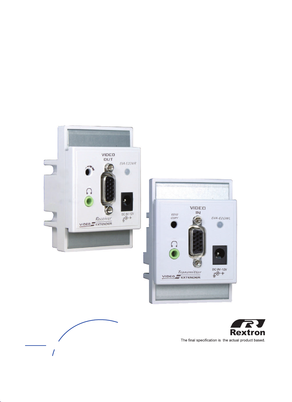
Overview
The wall-mount Video (+Audio) Extender consists of a
Transmitter and a Receiver that allows you to extend VGA
(+Audio) signal up to 165 meters away from a Video source by
using only a single UTP CAT5/ 5e/ 6 cable increasing the space
efficiency. It supports most of the popular Windows, Mac, Sun, and
Linux operating system.
The EDID Copy function on the Transmitter Unit enables the best
video presenting, and the RGB Skew feature on the Receiver Unit
allows manually and intuitively adjusting video quality according to
the length of CAT5 cable. Its compact design offers the convenient
installation and saves space where the display may need to expose
in a public area, but you can keep the system in a safe location. It
is perfect for situations that require immediate and easy to set up,
such as presentations from commercial product to corporate
financial data in showrooms, boardrooms, trade shows, window
displays, classrooms, and training facilities.
Available colors: ■ □
2
Features
zExtend video (+ audio) signal up to 165M away from a Transmitter
zSupport the video resolution up to 1920 x 1080 (Full HD), 1920 x
1200 (WUXGA)
zPlug-n-Play enabled in Windows, Mac, Sun and Linux platforms
zNo driver needed or software required
zEDID Copy function makes the best resolution presenting for
your application
zEQ (Sharpness) adjustment for optimal signal clarity
zSupport both DC jack or Terminal block power supply interface
zCompatible with most of the popular screen resolution to XGA, SXGA,
UXGA, WSXGA…Full HD, WUXGA
zEasy to get and install the CAT5/ 5e/ 6 cable at lower cost
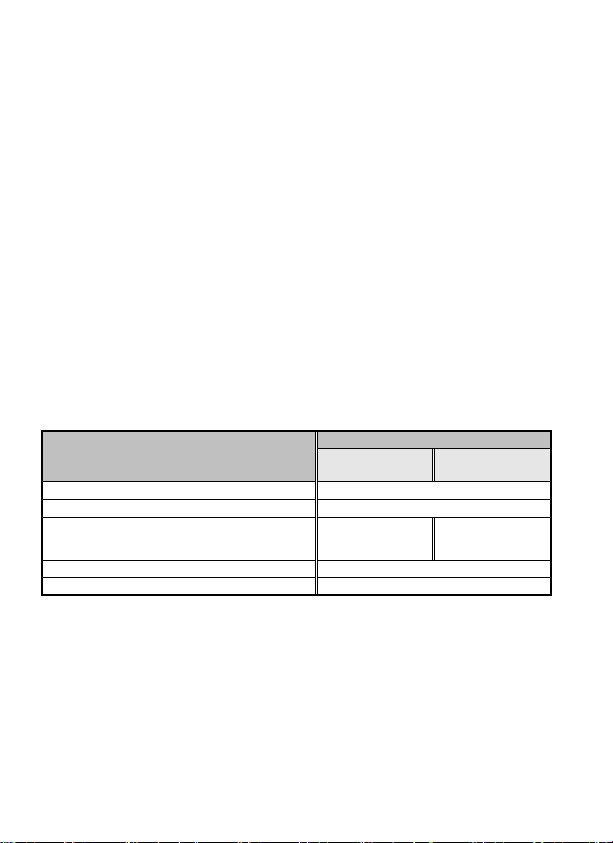
Package Contents
Quantity
Contents Video Type Video+ Audio
Type
Extender Transmitter Unit 1
Extender Receiver Unit 1
Power Adapter with necessary AC Cord
or
Plug-in Power Adapter
1
(Receiver Unit) 2
Screw package 1
User manual 1
3
------------------- Product Description
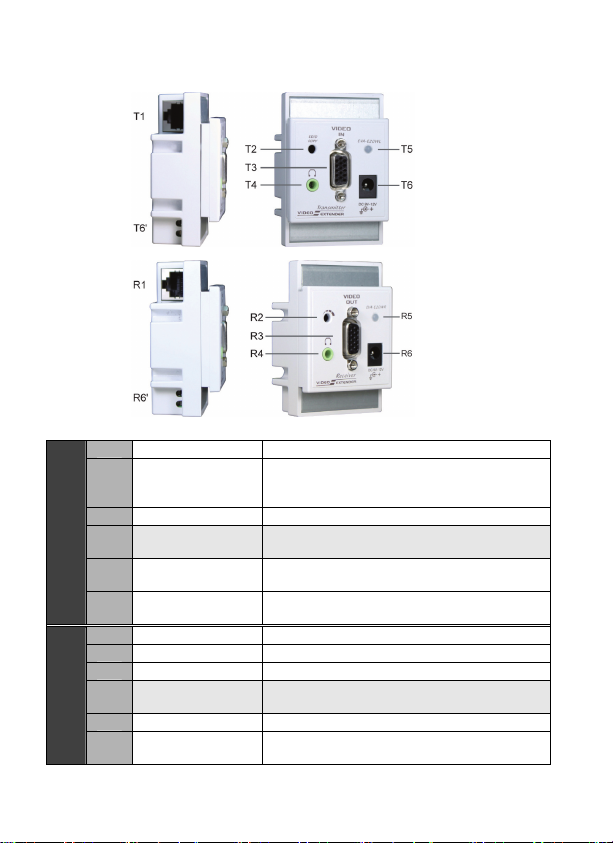
T1 RJ-45 Connector Connect to Receiver Unit
T2 EDID Copy Button
1. Copy the EDID of the connected (T3
)
monitor
2. Use the default EDID
T3 VGA Port Connect to a video source
T4 Audio Port Connect to a audio source
(depends on model)
T5 LED Indicator Green: Power ON
Red: EDID Copy Status (See Operation)
Transmitter
T6
T6’
DC jack
Terminal block DC 9-12V power supply
R1 RJ-45 Connector Connect to Transmitter Unit
R2 RGB Skew Manually adjust the video quality
R3 VGA Port Connect to VGA Monitor
R4 Audio Port Connect to the Speaker
(depends on model)
R5 Power LED Green: Power ON
Receiver
R6
R6’
DC jack
Terminal block DC 9-12V power supply

4
------------------- Installation
Before the installation
zPrior to the installation, ensure to power off all devices that will
be connected to this system.
zEnsure that all devices you will connect are properly grounded.
zPlace cables away from fluorescent lights, air conditioners, and
machines that are likely to generate electrical noise.
zThe extender pair requires only a single power supply, which can
be plugged in at either end of the link.
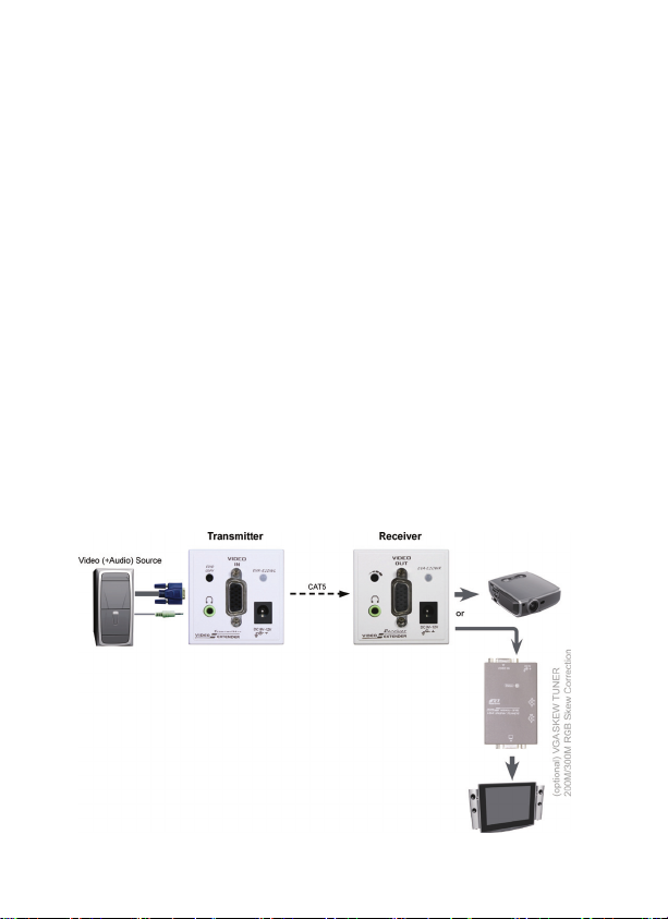
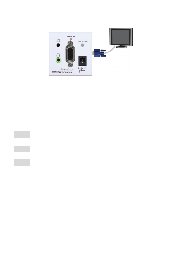
Transmitter
1. Connect one end of the VGA (Audio) cable to the VGA (Audio) port on
the source device (e.g. PC or DVD player)
2. Connect the other end of the cable to the VGA (Audio) port of the Unit
3. Basically the Transmitter is power-free operation and it draws little
power from Receiver Unit (except EDID Copy processing)
(Video+ Audio Type requires power supply on both ends)
Receiver
1. Plug monitor’s VGA cable into the VGA port on the Unit
Plug speaker’s audio cable into the audio port on the Unit
2. Use a CAT5 Cable for the connection between the Transmitter Unit
and the Receiver Unit.
3. Connect the provided power cord into an appropriate power source
and plug the opposite end into the power connector on the Unit. The
POWER LED on the top panel of the Unit illuminates GREEN
indicating the power ON.
NOTE: To improve video quality over long distance, try using a
screwdriver to adjust the video quality

5
Assembly
Step 1. Remove the 4 screws on the Extender Unit
Step 2. Install the Extender Unit inside the Wall-mount Box, as
figure shown below.
Extender Cover Wall-mount Cover Extender Unit Wall-mount Box
NOTE: The depth of the Wall-mount Box should not be less than 34mm

6
----------------- EDID Copy
EDID Copy for Transmitter Unit only
In some cases users may suffer from display problems due to
incorrect EDID communication between the display monitor and the
PC graphics card or insufficient EDID data programmed by display
manufactures. The Local Unit provide “EDID Copy” feature that
allows the Unit to read the necessary EDID information from the
attached video display and then provide it at all times to attached
computer. If no new EDID information is available from a display, a
default profile in the Local Unit (Transmitter) is automatically
provided instead.
To efficiently achieve EDID communication when the computer is
booting up, users are required to implement the EDID Copy on the
Local Unit (Transmitter)before the operations begin as described
below:
zUse (Load) default setting :
When using a monitor (without EDID compliant) for display. The
Unit will automatically select viable EDID data from the Unit’s
default EDID profile to set the EDID information up. Users can
achieve this EDID Copy by following the instructions below:
Step 1. Press and Hold the button “EDID Copy” on the unit and
release the button RIGHT AFTER the LED flashing red.
(6~7 sec)
Step 2. The power LED lighting steady GREEN indicating that
the EDID Copy is completed.
7
zCopy (new) monitor EDID:
When using a monitor (EDID compliant) for display, the Unit’s
EDID Copy function will enable the EDID communication
between the monitor and Unit for optimal video quality. Users
can achieve this EDID communication by following the
instructions below:
Step 1. Connect the monitor (EDID compliant) to the VGA Port
on the Unit and power on the monitor.
Step 2. Press the button “EDID Copy” and release the button
RIGHT AFTER the LED flashing green. (3~4 sec)
Step 3. The power LED lighting steady GREEN indicating that
the EDID Copy is completed.
Otherwise, if the LED flashes RED, it means that
a. The monitor is not properly connected
b. The monitor is not powered on
c. EDID data of the monitor is not applicable
Please repeat Step2 to 3 again
.

8
----------------- Appendix
Specification
Transmitter Receiver
UK Type EV-E20WL EV-E20WR
Video Germany
(Europe Type) EV-G20WL EV-G20WR
UK Type EVA-E20WL EVA-E20WRVideo
+
Audio
Germany
(Europe Type) EVA-G20WL EVA-G20WR
HDB15-F x 1 RJ-45 x 1
Input HDB15-F x 1
Audio jack x 1 RJ-45 x 1
RJ-45 x 1 HDB15-F x 1
Output RJ-45 x 1
HDB15-F x 1
Audio jack x 1
LED Power/ EDID Copy
(Dual Color) x 1 Power x 1
Video Resolution (Max.) 1920 x 1080 (Full HD), 1920 x 1200 (WUXGA)
Extension Distance 165 Meters*
Plastic Plastic
Enclosure Plastic Plastic
Weight (gram) 80g 80g
Power Supply DC 9-12V
*The better quality CAT5 cable the longer extend. And, the higher resolution
the shorter cable length.
9
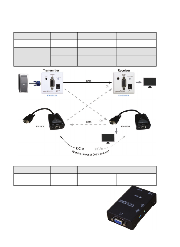
Related Products
Wall plate / Dongle Video Extender
Type Function Transmitter Receiver
Dongle Video EV-10DL EV-01DR
Video EV-A20WL EV-A20WR
US Type
Wallplate Video
+ Audio EVA-A20WL EVA-A20WR
VGA SKEW TUNER
Type Function RGB Calibration Distance (Max.)
200M 300MVGA SKEW
TUNER
Correct
RGB skew VSKU-215 VSKU-315
10
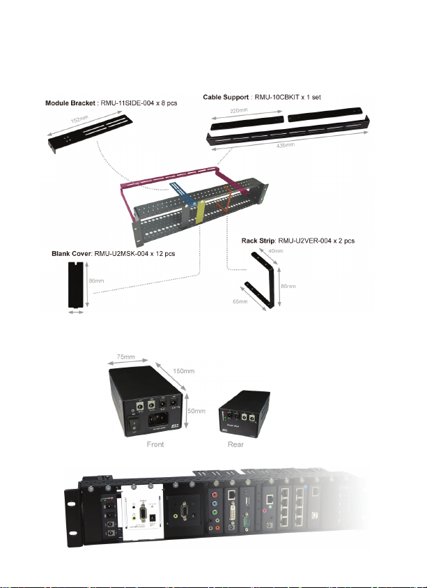
2U Rackmount Module Tray Kit: RMU-U2RACK
Power Hub (12V x 8): PHQ-50T

11
Limited Warranty
IN NO EVENT SHALL THE DIRECT VENDOR'S LIABILITY FOR DIRECT OR INDIRECT, SPECIAL,
INCIDENTIAL OR CONSEQUENTIAL DAMAGES, LOSS OF PROFIT, LOSS OF BUSINESS, OR
FINANCIAL LOSS WHICH MAY BE CAUSED BY THE USE OF THE PRODUCT EXCEEDS THE
PRICE PAID FOR THE PRODUCT.
The direct vendor makes no warranty or representation, expressed or implied with respect
to the contents or use of this documentation, and especially disclaims its quality,
performance, merchantability, or fitness for any particular purpose.
The direct vendor also reserves the right to revise or update the product or
documentation without obligation to notify any user of such revisions or updates. For
further information, please contact your direct vendor.
All the brand names and registered trademarks are the property of their respective owners.
CD5-VLE57ZZ-000
Printed in Taiwan
Table of contents


