Daikin LCBKQ3AV1 User manual

Booster Unit
INSTALLATION MANUAL
English
Deutsch
Français
Español
Italiano
Portugues
Nederlands
Installation manual
Booster Unit
Installationsanleitung
Zusatzgerät
Manuel d’installation
Unité d'accélération
Manual de instalación
Unidad booster
Manuale di installazione
Compressore ausiliario
Installatiehandleiding
Boostereenheid
Manual de instalação
Booster
Booster Unit
(LCBKQ3AV1(E))


English 1
LCBKQ3AV1(E) Booster Unit Installation manual
CONTENTS
1. FIRST OF ALL ......................................................................... 1
1-1 Safety Precautions ........................................................... 1
1-2 Special Notice of Product.................................................. 2
1-3 Disposal Requirements ..................................................... 2
2. BEFORE INSTALLATION........................................................ 2
2-1 Standard Supplied Accessories ........................................ 2
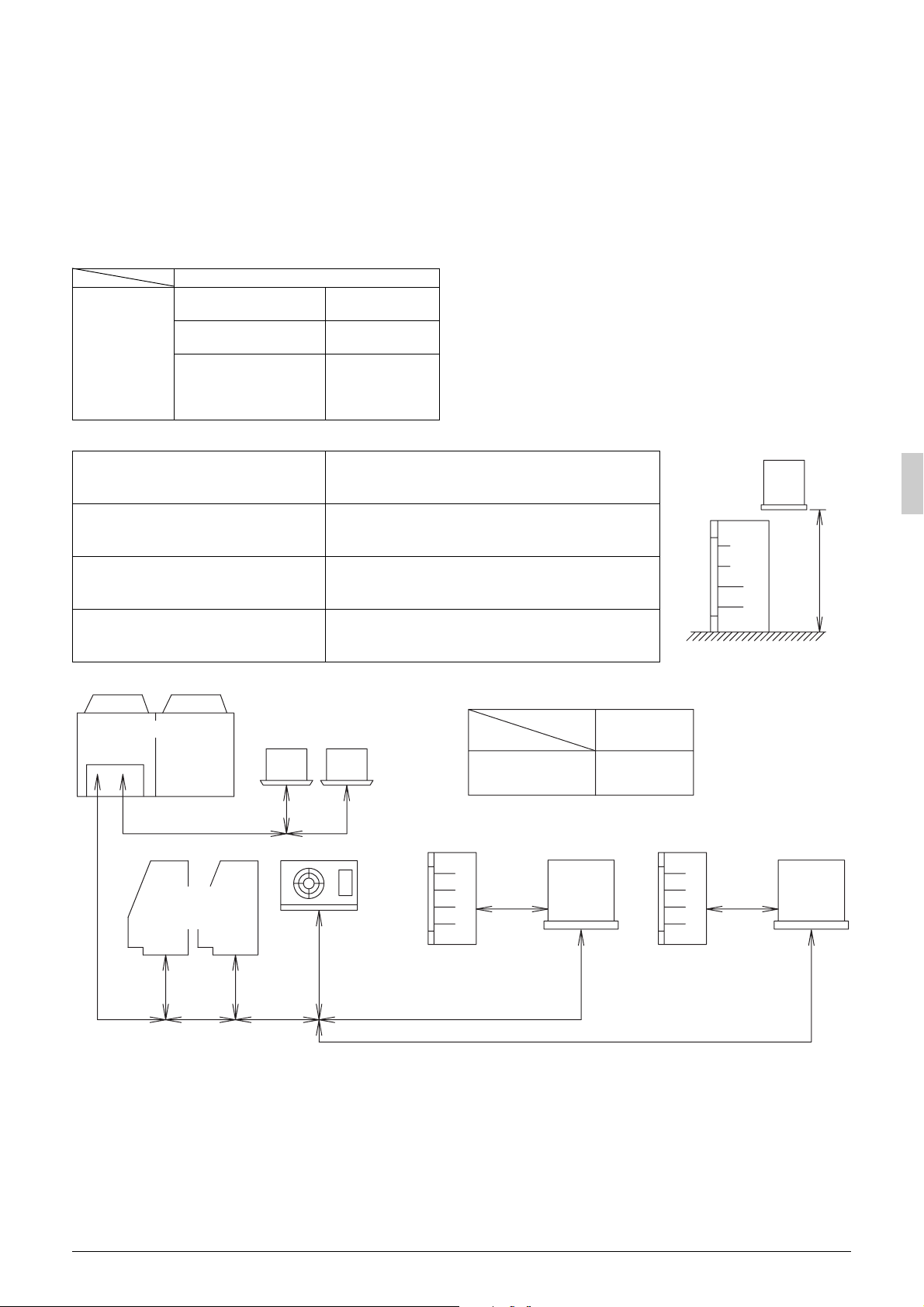
2-2 Example of System Configuration..................................... 2
2-3 Indoor Unit Constraints ..................................................... 3
3. SELECTION OF LOCATION ................................................... 3
4. PLACING THE UNIT................................................................ 3
4-1 Handling The Unit ............................................................. 3
4-2 Installation the Unit ........................................................... 4
4-3 Draining the Unit ............................................................... 4
4-4 Installation Procedure ....................................................... 4
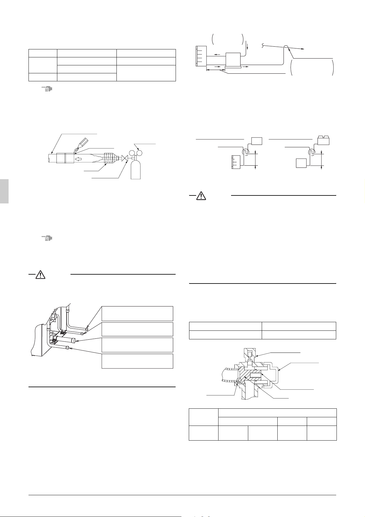
5. REFRIGERANT PIPING .......................................................... 4
5-1 Selection of Piping Material .............................................. 5
5-2 Protection against Contamination when
Installing Pipes.................................................................. 6
5-3 Pipe Connection................................................................ 6
5-4 Connecting the Refrigerant Piping .................................... 6
5-5 Air Tight Test / Vacuum Drying ......................................... 7
5-6 Thermal Insulation for Piping ............................................ 7
6. FIELD WIRING ........................................................................ 8
6-1 Example of Wiring Entire System ..................................... 9
6-2 Procedure for Incoming Wiring ......................................... 9
6-3 Wiring Connection........................................................... 10
6-4 Checking of Device and Installation Conditions .............. 10
7. CHECKS AFTER WORK COMPLETION .............................. 10
8. REFRIGERANT REPLENISHMENT...................................... 11
9. TEST RUN ............................................................................. 11
1. FIRST OF ALL
• This document is an installation manual for the Daikin Booster
Unit. Before installing the unit, read this manual thoroughly, and
following the instructions contained in it. After installation, do a
test run to make sure the unit runs properly, and then explain how
to operate and take care of the unit to the customer, using the
operation manual.
• Lastly, make sure the customer keeps this manual, along with the
operation manual, in a safe place.
•
This manual does not describe how to install the indoor unit and out-
door unit.
Refer to the installation manual included with the indoor unit and
outdoor unit for that.
1-1 Safety Precautions
Please read these “Safety precautions” carefully before installing the
booster unit and be sure to install it correctly.
After completing installation, conduct a trial operation to check for
faults and explain to the customer how to operate the booster unit
and take care of it with the aid of the operation manual. Ask the cus-
tomer to store the installation manual along with the operation man-
ual for future reference.
Meaning of WARNING and CAUTION notices
WARNING .....Failure to follow these instructions properly may
result in personal injury or loss of life.
CAUTION......Failure to observe these instructions properly
may result in property damage or personal
injury, which may be serious depending on the
circumstances.
WARNING
• Ask your dealer or qualified personnel to carry out installation
work.
Do not attempt to install the booster unit yourself. Improper
installation may result in water leakage, electric shocks or fire.
• Maintenance personnel of the manufacturer or equivalent skilled
personnel should install this unit.
• Install the booster unit in accordance with the instructions in this
installation manual.
Improper installation may result in water leakage, electric shocks
or fire.
• When installing the unit in a small room, take measures against to
keep refrigerant concentration from exceeding allowable safety
limits in the event of refrigerant leakage.
Contact the place of purchase for more information. Excessive
refrigerant in a closed ambient can lead to oxygen deficiency.
• Be sure to use only the specified accessories and parts for instal-
lation work.
Failure to use the specified parts may result in the unit falling,
water leakage, electric shocks or fire.
• Install the booster unit on a foundation strong enough to withstand
the weight of the unit.
A foundation of insufficient strength may result in the equipment
falling and causing injury.
• Carry out the specified installation work after taking into account
strong winds, typhoons or earthquakes.
Failure to do so during installation work may result in the unit fall-
ing and causing accidents.
• Make sure that a separate power supply circuit is provided for this
unit and that all electrical work is carried out by qualified person-
nel according to local laws and regulations and this installation
manual.
An insufficient power supply capacity or improper electrical con-
struction may lead to electric shocks or fire.
• Make sure that all wiring is secured, the specified wires are used,
and that there is no strain on the terminal connections or wires.
Improper connections or securing of wires may result in abnormal
heat build-up or fire.
• When wiring the power supply and connecting transmission wir-
ing, position the wires so that the control box lid can be securely
fastened.
Improper positioning of the control box lid may result in electric
shocks, fire or the terminals overheating.
• If refrigerant gas leaks during installation, ventilate the area
immediately.
Toxic gas may be produced if the refrigerant gas comes into con-
tact with fire.
• After completing installation, check for refrigerant gas leakage.
Toxic gas may be produced if the refrigerant gas leaks into the
room and comes into contact with a source of fire, such as a fan
heater, stove or cooker.
• Be sure to switch off the unit before touching any electrical parts.
• Do not directly touch refrigerant that has leaked from refrigerant
pipes or other areas, as there is a danger of frostbite.
• Do not allow children to climb on the outside unit and avoid plac-
ing objects on the unit.
Injury may result if the unit becomes loose and falls.
•
Be sure to earth the
booster
unit.
Do not earth the unit to a utility pipe, lightning conductor or
telephone earth lead. Imperfect earthing may result in
electric shocks or fire.
A high surge current from lightning or other sources may cause
damage to the booster unit.
• Be sure to install an earth leakage breaker.
Failure to install an earth leakage breaker may result in electric
shocks or fire.
CAUTION
• While following the instructions in this installation manual, install
drain piping to ensure proper drainage and insulate piping to pre-
vent condensation.
Improper drain piping may result in indoor water leakage and
property damage.

2English
• Install the indoor and outdoor units, power cord and connecting
wires at least 1 meter away from televisions or radios to prevent
picture interference and noise.
(Depending on the incoming signal strength, a distance of 1 meter
may not be sufficient to eliminate noise.)
• Do not install the booster unit in the following locations:
1. Where there is a high concentration of mineral oil spray or
vapour (e.g. a kitchen).
Plastic parts will deteriorate, parts may fall off and water leak-
age could result.
2.
Where corrosive gas, such as sulphurous acid gas, is produced.
Corroding of copper pipes or soldered parts may result in
refrigerant leakage.
3. Near machinery emitting electromagnetic radiation.
Electromagnetic radiation may disturb the operation of the
control system and result in a malfunction of the unit.
4. Where flammable gas may leak, where there is carbon fiber or
ignitable dust suspensions in the air, or where volatile flamma-
bles such as paint thinner or gasoline are handled.
Operating the unit in such conditions may result in fire.
5. Vehicles, ships, or other places that generate vibration or
cause the booster unit to move.
The booster unit may malfunction or cause oxygen deficiency
accidents as a result of refrigerant leakage.
6. Places with excessive voltage fluctuations.
The booster unit may malfunction.
7. Places where fallen leaves accumulate or weeds grow thick.
8. Places that become small animals’ shelter.
Small animals coming in contact with electrical parts can
cause malfunctions, smoke, or ignition.
• The booster unit is not intended for use in a potentially explosive
atmosphere.
1-2 Special Notice of Product
This booster unit comes under the term “appliances not acces-
sible to the general public”.
[CLASSIFICATION]
• This booster unit comes under the term “appliances not accessi-
ble to the general public”.
• Follow the showcase to be connected for the climate class.
[EMC CHARACTERISTICS]
This System is a class A product. In a domestic environment this
product may cause radio interference in which case the user may be
required to take adequate measures.
[REFRIGERANT]
Important information regarding the refrigerant used
This product is factory charged with N2.
The refrigerant system will be charged with fluorinated greenhouse
gases covered by the Kyoto Protocol. Do not vent gases into the
atmosphere.
Refrigerant type : R410A
GWP (1) value : 1975
(1) GWP = global warming potential
∗Values are indicated in F-gas regulations (EC) No.842/2006, Annex I,
Parts 1 and 2.
• The refrigerant R410A requires strict cautions for keeping the sys-
tem clean, dry and tight.
Read the chapter “REFRIGERANT PIPING” carefully and follow
these procedures correctly.
A.Clean and dry
Foreign materials (including mineral oils such as SUNISO oil or
moisture) should be prevented from getting mixed into the system.
B.Tight
Take care to keep the system tight when installing.
R410A does not contain any chlorine, does not destroy the
ozone layer, and does not reduce the earth’s protection against
harmful ultraviolet radiation.
R410A can contribute slightly to the greenhouse effect if it is
released.
• Since R410A is a mixed refrigerant, the required additional refrig-
erant must be charged in its liquid state. If the refrigerant is
charged in a state of gas, its composition changes and the system
will not work properly.
[DESIGN PRESSURE]
Since design pressure is 3.8MPa or 38bar (for R407C units : 3.3MPa
or 33bar), the wall thickness of pipes should be more carefully
selected in accordance with the relevant local and national regula-
tions.
1-3 Disposal Requirements
Dismantling of the unit, treatment of the refrigerant, oil and eventual
other parts, should be done in accordance with the relevant local and
national regulations.
2. BEFORE INSTALLATION
CAUTION
• When installing the indoor unit and the outdoor unit, refer to the
installation manual provided for the indoor unit and the outdoor
unit.
• Optional accessories are required for the installation of the prod-
uct. Refer to the information on optional accessory.
2-1 Standard Supplied Accessories
The following accessories are included. The storage location of the
accessories is shown in the figure.
Note
Do not throw away any of the accessories until installation is complete.
2-2 Example of System Configuration
Name Clamp Manual
Drain socket
Quantity 3 pcs. 1 pc. 1 pc.
Shape Installation
Manual
Name Drain receiver
Hole cap
Quantity 1 pc. 4 pcs.
Shape
Name Outdoor unit Booster unit
Shape
Name
Indoor unit
Air-conditioner Refrigeration
Blower coil Showcase
Shape
Name
Indoor unit
Control
panel
(Defrost)
Warning
panel
Remote con-
troller (for
air-
conditioner)
Freezer
Blower coil
Showcase
Shape

English 3
1Installation manual
2Clamps
2-3 Indoor Unit Constraints
• The design pressure for the indoor unit is 2.5 MPa or more.
• Install an R410A mechanical thermostatic expansion valve on
each indoor unit.
• Insulate the feeler block of the mechanical thermostatic expan-
sion valve.
• Install an R410A solenoid valve on the primary side of the
mechanical thermostatic expansion valve (Max. operating differ-
ential pressure of 3.5 MPa [35 bars] or over) described above for
each indoor unit.
• Install a filter on the primary side of the solenoid valve described
above for each indoor unit. Determine the filter mesh count based
on the size specified by the solenoid valve and mechanical ther-
mostatic expansion valve being used.
• Route the path to the indoor unit heat exchanger so that the flow
of refrigerant is from top to bottom.
• When installing a number of indoor units, be sure to install them at
the same level.
• Use the electric heater defrosting as the defrosting type. Hot-gas
defrosting models cannot be used.
3. SELECTION OF LOCATION
Select a location for installation that meets the following conditions.
Get the customer’s permission.
1. There is no danger of fire due to leakage of inflammable gas.
2. Select the location of the unit in such a way that the sound gener-
ated by the unit disturb anyone.
3. The foundation is strong enough to support the weight of the unit
and the floor is flat to prevent vibration and noise generation.
4. The piping length between the booster unit and outdoor unit or
between the booster unit and indoor unit may not exceed the
allowable piping length. (Refer to “REFRIGERANT PIPING”)
5. When installing the unit outdoors, install it preferably in a location
that is not exposed to rain.
6. The space around the unit is adequate for servicing and the min-
imum space for air inlet and air outlet is available.
(See the “Installation Space Examples” for the minimum space
requirements.)
Installation Space Examples
• During installation, install the units using the most appropriate of
the patterns shown in the following figure for the location in ques-
tion, taking into consideration human traffic and wind.
• As regards space in front of the unit, consider the space needed
for the local refrigerant piping when installing the units.
• If the work conditions in the following figure do not apply, contact
your dealer or Daikin directly.
CAUTION
1. An inverter booster unit may cause electronic noise generated
from AM broadcasting. Examine where to install the main booster
unit and electric wires, keeping proper distances away from ste-
reo equipment, personal computers, etc.
Particularly for locations with weak reception, ensure there is a
distance of at least 3 meters for indoor remote controllers, place
power wiring and transmission wiring in conduits, and ground the
conduits.
2. If condensate may drip on downstairs (or walkway) depending on
the floor condition, take a measure such as the installation of
drain pan kit (sold separately).
3. The refrigerant R410A itself is nontoxic, nonflammable and is
safe. If the refrigerant should leak however, its concentration may
exceed the allowable limit depending on room size. Due to this it
could be necessary to take measures against leakage.
See “Engineering Data” for details.
4. PLACING THE UNIT
4-1 Handling the Unit
1. Decide on the transportation route.
2. If hanging the unit, use a cloth sling to prevent damaging the unit.
Keeping the following points in mind, hang the unit following the
procedure shown in the following figure.
• Use the slings bearing product mass enough.
• Lift the unit with 2 belts of the at least 4m long.
• Put cushion cloth where the slings contact the casing.
• Lift the product with cave at the product center of gravity posi-
tion.
If using the handle of unit, carry the unit slowly with having the
handle.
1, 2
<When installed
as a single unit>
Piping slot
Booster unit
≥500mm
≥500mm ≥500mm
≥500mm ≥500mm
≥200mm ≥200mm
≥500mm ≥500mm
≥500mm
Front side Front side
<When installed in serial>
Power supply
Power supply
Power supply
Power
supply
Power supply
Unit cooler
Control
panel
Booster
unit
1.5m or more
1.5m or more
1.5m or more
1.5m or more
Control
panel
Alarm
panel
1.5m or more
1m or more
1.5m or more
1.5m or more
1m or more
1.5m or more
1.5m or more
1.5m or more
Remote
controller
Showcase
Indoor unit
Belt sling
Belt sling
Cushion cloth
Handle Hang on the edge
of the bottom plate.

4English
4-2 Installation the Unit
• Make sure the unit is installed level on a sufficiently strong base to
prevent vibration and noise.
•
Secure the unit to its base using foundation bolts. (Use four com-
mercially available M8-type foundation bolts, nuts, and washers.)
• The foundation bolts should be inserted 20 mm.
Note
• When installing on a roof, make sure the roof floor is strong
enough and be sure to water-proof all work.
• Make sure the area around the machine drains properly by setting
up drainage grooves around the foundation.
Drain water is sometimes discharged from the booster unit when
it is running.
• If the booster unit is of brine damage
resistant type, use nuts provided with
resin washers to secure the product to
the foundation bolts (see the illustra-
tion on the right-hand side).
The rustproof effect of the nut will be
lost if the coatings on the tightening portions of the nuts come off.
• Use the drain pan kit when using indoors.
<Model> BWC63A2
Ensure that sufficient drainage is supplied by following the guide-
lines below as necessary when using outdoors.
4-3 Draining the Unit
• For drainage work of the unit, install piping to ensure complete
drainage.
• Condensation may form on the bottom frame depending on the
condition of the installation location.
If the unit is installed in a poorly drained location, install an addi-
tional drain pan (optional accessory).
• Check drainage of the drain pan after completing the installation
work and make sure that the water runs smoothly.
4-4 Installation Procedure
1. Fit the drain holder to the top
of the drain socket prong.
2. Fit the drain socket in drain
hole-A of the bottom frame
of the unit and turn it about
40 degrees clockwise.
3. Plug hole caps in other drain
holes (B-E) from the under-
side to prevent water from
leaking.
4. Connect the hose to the
drain socket using a com-
mercial plastic hose (I.D. 25 mm) and a hose band.
If the hose is long and hangs, be careful not to bend it halfway
through.
If installing a drain hose directly to the booster unit, reserve the space
described above.
5. REFRIGERANT PIPING
To Piping Work Contractors
• Do not use flux at the time of brazing and connecting refrigerant
pipes. Use phosphorous copper brazing filler metal (BCuP-2),
which does not require flux. Chlorine-based flux causes piping
corrosion. Furthermore, if fluoride is contained, the flux will have
adverse influences on the refrigerant piping line, such as the dete-
rioration of refrigerating machine oil.
CAUTION
• All field piping must be installed by a licensed refrigeration tech-
nician and must comply with relevant local and national regula-
tions.
[Precautions for reuse of existing refrigerant piping / heat
exchangers]
Keep the following points in mind for the reuse of existing refrig-
erant piping / heat exchangers.
A malfunction may result if there is deficiency.
• Do not use the existing piping in the following cases. Perform new
piping instead.
• The piping is different in size.
• The strength of the piping is insufficient.
• The compressor of the booster unit previously used caused a
malfunction.
An adverse influence of residual substances, such as the oxi-
dation of refrigerant oil and the generation of scale, is consid-
ered.
• If the indoor unit or outdoor unit is disconnected from the piping
for a long time.
The intrusion of water and dust into the piping is considered.
• The copper pipe is corroded.
• The refrigerant of the booster unit previously used was other
than R410A (e.g., R404A / R507 or R407C).
The contamination of the refrigerant with heterogeneity is con-
sidered.
• If there are welded connections midway on the local piping, make
gas leakage checks on the welded connections.
• Be sure to insulate the connection piping.
The liquid and gas pipe temperatures are as follows:
Liquid pipe arrival minimum temperature:
5°C (For outdoor unit)
-10°C (To indoor unit)
Gas pipe arrival minimum temperature:
-45°C (For indoor unit)
100°C (To outdoor unit) (Max. temperature)
In the case of thickness insufficiency, add additional insulation
material or renew the existing insulation material.
• Renew the insulation material if the insulation material is
degraded.
Keep the following points in mind for the reuse of existing heat
exchangers
• Units with insufficient design pressure (since this product is an
R410A unit) require a lower-stage design pressure of 2.5 MPa
[25 bars].
• Units for which the path to the heat exchanger has been routed so
that the flow of refrigerant is from bottom to top
• Units with copper tubing or fan corrosion
• Units that may be contaminated with foreign matter such as rub-
bish or other dirt
20
20
Foundation bolt
allowance
Dimension of booster unit and
foundation bolt position
(Unit: mm)
180
320
680
650
Resin
washers
BD
E
A2
1Drain receiver
3 Hole cap
C
Drain hole position
Drain socket
4 Drain socket
Take it out down
Booster unit
Drain hose
≥300mm

English 5
5-1 Selection of Piping Material
•
Make sure that the inner side and outer side of the piping used is clean and free of contaminants, such as sulphur, oxide, dust, chips, oil and fat, and water.
It is desirable that the maximum oil adhesion in the piping is 30 mg per 10 m.
• Use the following type of refrigerant piping.
Material: Seamless phosphorus deoxidized copper tube (C1220T-O for a maximum outer diameter of 15.9 mm and C1220T-1/2H for a mini-
mum outer diameter of 19.1 mm)
Refrigerant piping size and wall thickness: Decide the size and thickness from the following table.
(This product uses R410A. The withstand pressure of O type may be insufficient if it is used for piping with a minimum diameter of
19.1 mm. Therefore, be sure to use 1/2 H type with a minimum thickness of 1.0 mm.
If O type is used for piping with a minimum diameter of 19.1 mm, a minimum thickness of 1.2 mm will be required. In that case, be
sure to perform the blazing of each joint.)
• Be sure to perform piping work within the range specified in the following table.
<Refrigerant piping size>
<Refrigerant piping length and permissible difference in height>
Refer to the installation manual of the outdoor unit for the indoor unit.
<Example of piping connection>
Piping size (O. D. × min. thickness)(mm) (Note 1)
Liquid piping inlet (Main liquid piping between booster unit and outdoor
unit)
Liquid piping outlet (Between booster unit and refrigeration showcase)
Suction piping (Between booster unit and refrigeration showcase)
Discharge piping (Main gas piping between booster unit and outdoor unit)
(Note 2)
If the size of the connection pipe of the refrigerating showcase exceeds
that of the branch pipe shown in the table on the left, install piping near the
refrigerating showcase.
LCBKQ3AV1(E)
Liquid piping inlet, outlet
(Note 1) (Note 2) φ6.4×0.8 (O type)
Suction piping (Note 1)
(Note 2) φ15.9×1.0(O type)
Discharge piping
(Note 1) φ9.5×0.8(O type)
Max. permissible one way piping length
(equivalent length) a + b + c + d ≤ 130m (d is d1, d2, or e whichever is longer)
Max. branch piping length (actual length)
g ≤ 30m (d is d1, d2, or e whichever is longer)
b + f ≤ 30m
b + c + d ≤ 30m
Between booster unit and refrigeration
showcase (equivalent length) i ≤ 30m
Max. difference in height between booster
unit and refrigeration showcase (refer to the
right figure)
0 ≤ H ≤ 10m (Refer to the right figure)
Booster
Unit
Showcase
H
Floor
<No. of connection of booster unit>
LRYEQ16AY1
Outdoor unit
a
b
gf
e
d1
ii
d2
c
Indoor unit
(Air-conditioning)
Refrigeration
showcase
Unit cooler
(Refrigeration) Freezer
showcase
Freezer
showcase
Booster
unit
Booster
unit
Max. no. of connection
of booster unit
2

6English
5-2 Protection against Contamination when
Installing Pipes
Protect the piping to prevent moisture, dirt, dust, etc. from entering
the piping.
Note
Exercise special caution to prevent dirt or dust when passing piping
through holes in walls and when passing pipe edges to the exterior.
5-3 Pipe Connection
•
Be sure to perform nitrogen permutation or nitrogen blow when brazing.
Brazing without performing nitrogen permutation or nitrogen blow
into the piping will create large quantities of oxidized film on the
inside of the pipes, adversely affecting valves and compressors in
the refrigerating system and preventing normal operation.
• The pressure regulator for the nitrogen released when doing the
brazing should be set to 0.02 MPa (about 0.2kg/cm2:Enough to
feel a slight breeze on your cheek).
Note
Do not use anti-oxidants when brazing the pipe joints.
Residue can clog pipes and break equipment.
5-4 Connecting the Refrigerant Piping
CAUTION
• Do not connect an onsite piping to an incorrect one. Wrong con-
nection will cause a malfunction.
Remove the piping slot cap before connecting the pipe.
• Do not let the onsite piping contact other piping, the bottom frame
and the side panel of the product.
Precautions for piping
• Always connect the piping within the range of the max. permissi-
ble piping length and the permissible difference in height.
• Bend the pipe allowing for a possibly large diameter. Do not bend
the pipe repeatedly.
• Install a gauge joint to install the pressure sensor on the inlet and
outlet pipes of the booster unit when connecting the AIRNET sys-
tem (Refer to the Service Manual for details).
• Create a trap on the gas pipe at 5 m intervals if the outdoor unit is
located above the booster unit (to ensure the smooth return of oil
in the riser pipe (Refer to Figure 1below)).
• Create a trap on the gas pipe at 5 m intervals if the booster unit is
located below the outdoor unit (to ensure the smooth return of oil
in the riser pipe (Refer to Figure 2below)).
Operation Method of Shutoff Valves
Follow the instructions below when operating each shutoff valve.
CAUTION
• Do not open the shutoff valve until the steps specified in
“6-4 Checking of Device and Installation Conditions” is com-
pleted.
Do not leave the shutoff valve opened without turning the power
on, otherwise refrigerant may be condensed in the compressor
and the insulation of the main power supply circuit may be
degraded.
• Be sure to use an exclusive tool to handle the shutoff valve. The
shutoff valve is not of back sheet type. Excessive force imposed
may break the valve.
• Use a charge hose when using the service port.
• Make sure that there is no refrigerant gas leakage after the valve
cover and cap are securely tightened.
〈Tightening torque〉
Check with the following table the sizes of shutoff valves incorporated
by each model and the tightening torque values of the respective
shutoff valves.
Shutoff valve sizes
〈Opening method〉
1. Remove the valve cover and turn the shaft anticlockwise with a
hexagon wrench.
2. Turn the shaft until the shaft stops.
3. Tighten the valve cover securely. Refer to the above table for the
tightening torque according to the size.
Place Installation period Protection method
Outdoor More than a month Pinch the pipe
Less than a month Pinch or tape the pipe
Indoor Regardless of the period
Refrigerant pipe
Regulator
Handy valve
Taping
Nitrogen
Nitrogen
Location to
be brazed
ALiquid piping inlet
Connect the pipe to the liquid pipe
(refrigeration) of the outdoor unit.
BLiquid piping outlet
Connect the pipe to the liquid pipe
of the refrigeration showcase.
CSuction pipe
Connect the pipe to the gas pipe of
the refrigeration showcase.
DDischarge pipe
Connect the pipe to the gas pipe
(refrigeration ) of the outdoor unit.
Liquid side shutoff valve φ9.5
Gas side shutoff valve φ9.5
Shutoff
valve sizes
Tightening torque N•m (closes clockwise)
Shaft (valve body) Valve cover Service port
φ9.5 5.4~6.5
Hexagon
wrench: 4mm
13.5~16.5 11.5~13.9
A
B
Liquid piping outlet
C
Suction
piping
DDischarge piping
Refrigeration
showcase
Refer to the
pipe diameter of
the showcase
Booster
unit
Liquid
piping
outlet
Set the
piping such
that it slants
downward.
Main gas piping of
outdoor unit
(refrigeration)
Connect from the upper
part of the main pipe
To prevent the unit from oil
and liquid refrigerant flowing
in from the main pipe while
the booster unit is stopped
Piping length shall be 30 m or less.
12
When the refrigeration
showcase is below the
booster unit
When the outdoor
unit is above the
booster unit
Create a trap Create a trap
Refrigeration showcase Booster unit
Booster
unit
Outdoor
unit
About
5m
About
5m
Service port
Valve cover
Hexagon hole
Shaft
Sealing part

English 7
〈Closing method〉
1. Remove the valve cover and turn the shaft clockwise with a hexa-
gon wrench.
2. Tighten the shaft until the shaft comes in contact with the sealing
part of the valve.
3. Tighten the valve cover securely. Refer to the above table for the
tightening torque according to the size.
〈Handling Precautions for Valve Cover〉
• Be careful not to damage the sealing part.
• At the time of mounting the valve cover, apply a screw lock agent
to the screw thread.
• Do not apply a screw lock agent (for flare nut use) to the sealing
part.
• Be sure to tighten the valve cover securely after operating the
valve. Refer to “Operation Method of Shutoff Valves” for the
tightening torque of the valve.
〈Handling Precautions for Service Port〉
• Work on the service port with a charge hose provided with a push-
ing rod.
• At the time of mounting the cap, apply a screw lock agent to the
screw thread.
• Do not apply a screw lock agent (for flare nut use) to the sealing
part.
• Be sure to tighten the cap securely after the work. Refer to “Oper-
ation Method of Shutoff Valves” for the tightening torque of the
cap.
CAUTION
Apply a screw lock agent to the valve cover mount and the
screw thread of the service port.
Otherwise, dew condensation water will intrude inside and freeze.
Therefore, refrigerant gas leakage or a compressor malfunction may
result from the cap deformation or damage.
5-5 Air Tight Test / Vacuum Drying
Ensure the following tests have been conducted after piping.
• Check that the gas side and liquid side shutoff valves are open.
• Air tight test - Always use the nitrogen gas.
Pressurize the high pressure side (liquid side) to the design pres-
sure (3.8MPa) of the outdoor unit and pressurize the low pressure
side (suction side) to the design pressure (2.5MPa) of the indoor
unit (field supplied).
In this case, they shall be accepted if no pressure drop is found for
24 hours through pressurization at least 5 minutes from the port
Aand the liquid shutoff port shown in the right figure.
Check if there are any leakage areas in the case of pressure drop.
• Vacuum drying - Refer to the installation manual of the outdoor
unit.
5-6 Thermal Insulation for Piping
• Always insulate connection pipes and branch pipes on the dis-
charge, suction and liquid sides.
The liquid and gas pipe temperature are as follows:
Liquid pipe arrival minimum temperature:
5°C (For outdoor unit)
-10°C (To indoor unit)
Gas pipe arrival minimum temperature
-45°C (For indoor unit)
100°C (To outdoor unit) (Max. temperature)
• Use a discharge pipe whose heat resistance is 120ºC or more as
its maximum temperature reaches about 100ºC. Use a suction
pipe and liquid pipe whose heat resistance is 80ºC as the stan-
dard specification.
• Refer to the installation manual attached to the outdoor unit for the
outdoor unit side.
CAUTION
• Always insulate the pipe joint for onsite piping.
(An exposed pipe can cause dew condensation and burn by con-
tact.)
Screw thread
Apply a screw lock agent
Sealing part
Not apply a screw lock agent
Shutoff valve
Part of mounting the
valve cover.
Valve cover
Sealing part
Not apply a screw
lock agent
Screw thread
Apply a screw lock
agent
Cap
Port A
Liquid side shutoff
valve port
Insulation (field supply)
Connect piping up to the
joint so that piping may not
be exposed.
(Heat resistance: 120ºC or more)
Insulation (field supply)
Liquid piping inlet
(between booster unit and
main liquid pipe)
Liquid piping outlet (between
booster unit and refrigeration
showcase)
Suction pipe
Discharge pipe

8English
6. FIELD WIRING
To Electric Engineering Contractors
• Be sure to install an earth leakage breaker. The product incorpo-
rates inverter equipment. In order to prevent the malfunctioning of
the earth leakage breaker, make sure that the earth leakage
breaker withstands harmonic interference.
• Do not operate the booster unit until refrigerant piping work is
completed, or otherwise the compressor will malfunction.
• Do not remove any electrical components such as thermistors or
sensors when connecting power supply wires or transmission
wires. The compressor may malfunction if the booster unit is oper-
ated with such electrical components removed.
CAUTION
• All field wiring and components must be installed by a licensed
electrician and must comply with relevant local and national reg-
ulations.
• Be sure to use a dedicated power circuit. Never use a power sup-
ply shared by another appliance.
• Never install a phase advancing capacitor. As this unit is equipped
with an inverter, installing a phase advancing capacitor will not
only deteriorate power factor improvement effect, but also may
cause capacitor abnormal heating accident due to high-frequency
waves.
• Only proceed with wiring work after blocking off all power.
• Always ground wires in accordance with relevant local and
national regulations.
• This machine includes an inverter device. Connect earth and
leave charge to eliminate the impact on other devices by reducing
noise generated from the inverter device and to prevent leaked
current from being charged in the outer hull of the product.
• Do not connect the ground wire to gas pipes, sewage pipes, light-
ning rods, or telephone ground wires.
Gas pipes: can explode or catch fire if there is a gas leak.
Sewage pipes: no grounding effect is possible if hard plastic pip-
ing is used.
Telephone ground wires and lightning rods: dangerous when
struck by lightning due to abnormal rise in electrical potential in
the grounding.
• Be sure to install an earth leakage circuit breaker.
This unit uses an inverter, so install the earth leakage circuit
breaker that be capable of handling high harmonics in order to
prevent malfunctioning of the earth leakage circuit breaker itself.
• Earth leakage circuit breaker which are especially for protecting
ground-faults should be used in conjunction with main switch or
fuse for use with wiring.
• Electrical wiring must be done in accordance with the wiring dia-
grams and the description herein.
• Do not operate until refrigerant piping work is completed.
(If operated before complete the piping work, the compressor may
be broken down.)
• Never remove thermistor, sensor or etc. when connecting power
wiring and transmission wiring.
(If operated with thermistor, sensor or etc. removed, the compres-
sor may be broken down.)
• This product have reversed phase protection detector that only
works when the power is turned on. If there exists black out or the
power goes on and off which the product is operating, attach a
reversed phase protection circuit. Running the product in
reversed phase may break the compressor and other parts.
• Attach the power wire securely. Introducing power with a missing
N-phase or with a mistaken N-phase will break the unit.
• Never connect the power supply in reversed phase.
The unit can not operate normally in reversed phase.
If you connect in reversed phase, replace two of the three phases.
• Make sure the electrical unbalance ratio is no greater than 2%. If
it is larger than this, the unit’s lifespan will be reduced.
If the ratio exceeds 4%, the unit will shut down and an malfunction
code will be displayed on the indoor remote controller.
• Connect the wire securely using designated wire and fix it with
attached clamp without applying external pressure on the termi-
nal parts (terminal for power wiring, terminal for transmission wir-
ing and earth terminal).
• A switch that allows all poles to be switched on and off from the
main power supply must be installed.
This switch must have a contact gap of at least 3 mm.

English 9
6-1 Example of Wiring Entire System
Note
• Use conduit for power supply wiring.
• Make sure the weak electric wiring (i.e. for the remote controller,
between units, etc.) and the power wiring do not pass near each
other, keeping them at least 50 mm apart.
Proximity may cause electrical interference, malfunctions, and
breakage.
• Be sure to connect the power wiring to the power wiring terminal
block and secure it as described in “6-2 Procedure for Incoming
Wiring”.
• Do not connect the power supply to the terminal block for the
transmission wiring for warning, alarm, operation output, and
remote operation switch. Otherwise the entire system will be dam-
aged.
• Transmission wiring should be secured as described in “6-3 Wir-
ing Connection”.
• Secure wiring with clamp such as insulation lock ties to avoid con-
tact with piping.
• Shape the wires to prevent the structure such as the control box
lid deforming. And close the cover firmly.
6-2 Procedure for Incoming Wiring
• Route high voltage wiring (power supply wire, earth wire and
refrigeration operation output wiring) through the wiring openings
located on the side of the unit (through holes on the left side).
• Route low voltage wiring (transmission wire, refrigeration opera-
tion input wiring and remote switch wire) through the wiring open-
ings located on the side of the unit (through holes on the right
side).
Timer for refrigeration
Timer for freezer
Note:3. In case of the malfunction Constant a-contact output
Relay
Alarm panel
Warning output
Caution output
Branch switch
Overcurrent
circuit breaker
Refrigeration operating output
Freezer operation output
Indoor
unit
Booster unit
Remote switch
(Note 1)
Remote
controller
In-Out Out-Out
Thermostat for inner temperature adjustment
Defrost completion thermostat
Solenoid valve
Electromagnetic contactor
(Defrost heater)
Defrost lamp
Integrated heat control board (Field supply)
Timer for freezer
Timer for refrigeration
For freezer
For refrigerator
ST controller
Showcase interface
Warning
input Sensor
input
Freezer showcase
Refrigeration unit cooler
Refrigeration showcase
3 phase 380-415V
Earth leakage circuit breaker
(High-frequency type)
(For earth fault, overload and
short-circuit protection)
AC 220-240V
Earth leakage circuit
breaker
(High-frequency type)
(For earth fault,
overload and short-
circuit protection)
(Note 1)
Remote switch
Earth leakage circuit breaker
(For earth fault, overload and
short-circuit protection)
Outdoor
unit
Caution
input
Warning
input
(Note 3)
(Note 3)
Note:1. For Remote switch, use non-voltage contact for microcurrent (not more than 1mA, 12VDC)
Note:2. Total capacity for warning, alarm : 0.5A or less at AC 220 to 240V.
Capacity for operation output : 0.5A or less at AC 220 to 240V.
Wiring diagram label
(back of the cover of the electric
accessory box)
Electric wiring, earth wire
(high voltage)
Transmission wire
(low voltage)

10 English
• Block the gap (shaded area shown in the figure below) with seal-
ing material such as putty if an intrusion by small creatures is pos-
sible.
6-3 Wiring Connection
High voltage wiring (Power supply wiring, Refrigeration opera-
tion output wiring, and earth wire)
• When two wires are connected to a single terminal, connect them
so that the rear sides of the crimp contacts face each other.
• Also, make sure the thinner wire is on top, securing the two wires
simultaneously to the resin hook using the accessory clamp (1).
Power circuit, safety device, and cable requirements
• A power circuit (see the following table) must be provided for con-
nection of the unit. This circuit must be protected with the required
safety devices, i.e. a main switch, a slow blow fuse on each phase
and an earth leakage circuit breaker.
• Use copper conductors only.
• Use insulated wire for the power cord.
• Select the power supply cable type and size in accordance with
relevant local and national regulations.
• Specifications for local wiring are in compliance with IEC60245.
• Use wire type H05VV when protected pipes are used.
• Use wire type H07RN-F when protected pipes are not used.
Refrigeration operation output wire specifications
CAUTION
• Refer to the “6-1 Example of Wiring Entire System” by all
means when connecting the operation output wiring.
A compressor failure may result if the operating output wiring is
not connected.
Low voltage wiring (transmission wire, refrigeration operation
input wiring and remote switch wire)
Connect low voltage wiring between the booster unit and the outdoor
unit, the booster unit and the integrated heat control board and the
remote switch by referring to the figure below.
<Precautions for low voltage wiring>
• Never connect the 220-240V power supply to the terminal block of
low voltage wiring. The entire system could be damaged.
• Isolate low voltage wiring from high voltage wiring (power supply
wire, refrigeration operation output wiring and earth wire) by at
least 50 mm.
• Always install low voltage wiring using vinyl cord with a 0.75-1.25
mm2sheath or cable (duplex).
• Install low voltage wiring within the limit described below. Exceed-
ing the limit can cause transmission problems.
Distance between the booster unit and the outdoor unit: 100 m
<Connection for transmission wire and refrigeration operation
input wiring>
<Connection for remote switch wire>
• Set the operation switch to “Remote” as shown in the figure below
to remotely start up and shut down.
• Use a remote switch that has a contact assuring the minimum
applicable load of DC12V/1mA.
6-4
Checking of Device and Installation Conditions
Be sure to check the followings.
<For those doing electrical work>
See “6-2 Procedure for Incoming Wiring”.
1.
Make sure there is no faulty power wiring or loosing of a nut.
See “6-3 Wiring Connection”.
2. Has the insulation of the main power circuit deteriorated?
Measure the insulation and check the insulation is above regular
value in accordance with relevant local and national regulations.
<For those doing pipe work>
1. Make sure piping size is correct.
See “5-1 Selection of Piping Material”.
2. Make sure insulation work is done.
See “5-6 Thermal Insulation for Piping”.
3. Make sure there is no faulty refrigerant piping.
See “5. REFRIGERANT PIPING”.
7.
CHECKS AFTER WORK COMPLETION
• Make sure the following works are complete in accordance with
the installation manual.
Piping work
Wiring work
Air tight test/Vacuum drying
Installation work for indoor unit (Refrigeration unit cooler,
refrigeration showcase, freezer showcase, air-conditioner)
Installation work for outdoor unit
Drainage water
Phase and
frequency Voltage
Minimum
circuit
amp.
Recom-
mended
fuses
LCBKQ3AV1
φ
1, 50Hz 220-240V 15A 20A
Electric wire thickness 0.75~1.25mm2
Max. wiring length 130m
Do not touch the high pressure
piping in the shaded area
during wiring.
Gap
(Block with sealing
material.)
Power supply
(1 phase 220~240V)
Earth wire
Power supply
terminal block
Earth wire
Attach the
insulation sleeve
Power supply wire
Earth terminal
X1M
X1M
Overcurrent
circuit breaker
(Earth leakage
circuit breaker)
Refrigeration operation
output wiring
Fix refrigeration operation
output wiring (S1, S2) with
the attached clamp.
Fix power supply wiring
(L/N phases) with the
attached clamp
LN
Terminal block
Crip style terminal
Wire: narrow
Clamp (1)
Wire: thick
Resin hook
High voltage wiring Low voltage wiring Transmission wire
Refrigeration operation
input wiring
Refrigeration operation input wiring
<Outdoor unit>
F1F2 F1F2 F1F2 T1T2 F1F2
12
In-Out
Out-Out
Out-Multi
In-Out
<Booster unit>
50mm or more
Transmission
wire
Never connect the power supply wire
Fix low voltage wiring
with the attached clamp
REMOTE
ON
OFF
REMOTE
ON
Remote switch
(between 1 and 2)
Ú
Constant a-contact input
OFF

English 11
8. REFRIGERANT REPLENISHMENT
Operation the booster is not needed to replenish refrigerant.
Follow the installation manual of the outdoor unit for the replenish-
ment procedure.
9. TEST RUN
For test run operators
Do not operate the outdoor unit alone on a trial basis.
Use the following procedure to perform a test run after installation
work is complete for the entire system:
Test run procedure
1. Fully open the shutoff valves on the gas and liquid side of the out-
door unit and the booster unit.
2. Check that the electric accessory box lids of the outdoor unit, the
booster unit and the indoor unit (air-conditioner, refrigeration
showcase, refrigeration unit cooler) and the piping cover of the
outdoor unit and the booster unit are closed.
Then turn on the outdoor, the booster unit and indoor units (air
conditioner, refrigeration showcase, refrigeration unit cooler).
3. Turn on the operation switch from the inspection door of the out-
door unit and the booster unit. (The outdoor fan rotates in about
10 minutes after the operation switch is turned on and the com-
pressor starts.)
4. Push the ON/OFF button on the remote controller of the outdoor
unit (air-conditioner) to operate the unit.
5. Check the sealing condition through the sight glass of the outdoor
unit. In case of shortage of refrigerant, check if the refrigerant is
charged to the specified level.
6. Check the following on each unit.
7. Be sure to turn off the operation switch before turning off the
power.
Error diagnosis
• Check the following if nothing is displayed on the remote controller
during the test run.
<Indoor unit (air-conditioner)>
1. Is the power turned on?
2. Is the wire broken or incorrectly wired (between the power, the
indoor unit and the remote controller)?
3. Has the fuse on PCB melted?
• If you have changed the power wire and the transmission line,
keep the power of the indoor unit (air conditioner, refrigeration
showcase, refrigeration unit cooler) and the integrated heat con-
trol board turned on, turn off the operation switch of the outdoor
units and never fail to press the push button switch (BS5) on PCB
(A1P) in the electric accessory box (right) of the outdoor unit for at
least 10 seconds (Open the inspection door (right) on the upper
right portion of the electric accessory box and operate the push
button switch (BS5) using an insulating rod). (See the right figure.)
• Refer to the Service Manual for other malfunction codes.
• Take the following action if you find a malfunction code on the
remote controller during the test run.
*1
Set the operating switch to the “OFF” position to reset the power sup-
ply and then return the switch to the “ON” position to restart the unit.
If the problem persists, refer to the Service Manual.
CAUTION
• Do not disconnect the power supply for 1 minute after setting the
operating switch to “ON”.
Electric leak detection is performed for several seconds after the
operating switch is set to “ON” and each compressor starts oper-
ating, so disconnecting the power supply during that time will
result in a false detection.
For dealers
• After the test run is finished, check that the piping cover and front
panel are mounted.
• At the time of delivery to the customer, use the Operation Manual
and fully explain the handling of the equipment.
• For precautions at the time of delivery, refer to the provided Instal-
lation Manual for each unit as well.
Refrigeration showcase
Cold air should be blowing and the temper-
ature should decrease to the preset level.
The unit should start defrosting operation
by the time set on the timer.
Refrigeration unit cooler
Cold air should be blowing and the temper-
ature should decrease to the preset level.
The unit should start defrosting operation
by the time set on the timer.
Air-conditioner Cold air (or hot air) should be blowing.
Inspection door (right)
(Upper right portion of the electric accessory box)
Malfunction
code Defect at installation Action to be taken
E3, E4 Shutoff valves closed Fully open the shutoff
valves.
EJ
Wiring error or booster mal-
function of the transmission
wire between the booster
and the outdoor unit
Check the transmission wire
between the booster and the
outdoor unit.
If the malfunction code per-
sists, check the LED on the
print board (A2P) in the elec-
tric accessory box of the
booster unit. Refer to the
Service Manual for the
checking method.
L4 The air passage is blocked. Remove obstacles blocking
the air passage.
U1 Reverse-phase of the power
supply
Exchange two wires out of
three power supply wires.
U2 Voltage drop Check the voltage drop.
U4, UF Wrong wiring of transmis-
sion lines between units
Check the connection of
transmission lines between
the outdoor unit and the air
conditioner.
UA In the case of system dis-
crepancy
Check if the air conditioner is
connected as should be
assembled.
E2 Electric leak See *1.

3P248411-5B EM09A056 (1002) FS
This manual suits for next models
1
Table of contents
Other Daikin Extender manuals