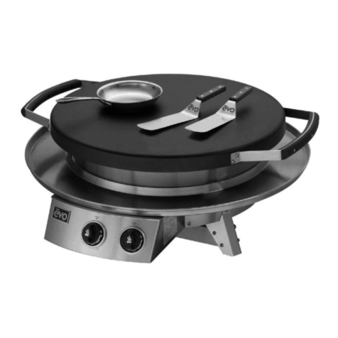
Evo AGA AGA-10-0096-LP-CE Installation instructions

R
For Outdoor Use Only.
Do Not Use Indoors.
by
05/2021 EINS 517915
LPRT 517914
AGA Professional Series Outdoor Gas Grills
25G drop in cooktop
For use in GB and IE
PLEASE READ THESE INSTRUCTIONS BEFORE USING THIS APPLIANCE
AND KEEP IN A SAFE PLACE FOR FUTURE REFERENCE.
Installations & Operation Instructions
CAUTION: THIS UNIT IS HEAVY, PROPER EQUIPMENT AND ADEQUATE MANPOWER MUST BE USED IN MOVING THE
RANGE TO AVOID DAMAGE TO THE UNIT OR THE FLOOR.
REMEMBER, when replacing a part on this appliance, use only spare parts that you can be assured conform to the safety and
performance specication that we require.
DO NOT use reconditioned or copy parts that have not been clearly authorised by AGA.

II
Useful Information
It maybe useful to make a note of your AGA appliance Serial
Number when it is being installed.
The serial number can be found on the right hand side of the
control panel.
Warranty terms & conditions
Your manufacturer’s warranty covers your AGA Outdoor
grill for defective workmanship for a period of two years
including labour and parts.
This warranty covers mechanical breakdown and proven
cosmetic and manufacturing defects.
To make certain your warranty remains valid you must
ensure:
• The appliance has been connected correctly to the
gas cylinder as per the recommendations of the
manufacturer of the regulator which are included in the
instructions supplied with the appliance.
• Has been used solely in a domestic environment for
domestic purposes.
• Is not a second hand or refurbished appliance.
• Has not been subject to misuse, accidental damage
or modification or repair (other than an approved
warranty repair) and has not deteriorated due
to normal domestic wear and tear and that the
manufacturer’s recommendations concerning cleaning
materials has been followed.
Return to base repair policy – In the event of your grill being
identied as faulty please contact our support team who will
assess the problem and oer telephone support to rectify the
issue. In the event that a repair is required we may request
that that the grill is collected by ourselves and returned to
our premises to complete any rectication work required. On
completion of the repair we will return the product back to
yourselves.
PLEASE NOTE: The manufacturer’s warranty is not
transferable.
What is not covered by this
warranty:
Conditions and damages resulting from any of the
following:
• Improper or inadequate installation, delivery, use,
storage or maintenance
• Any repair not authorised in writing by AGA
Rangemaster Ltd, any modifications, misapplications, or
unreasonable use
• Improper setting of any control
• Harsh environmental conditions, including, but not
limited to, continual seawater spray, high pressure
water, and direct contact with corrosive chemicals and
materials
• Excessive or inadequate electrical, or gas supply
• Accidents, natural disasters, acts of God
• Conditions covered by the purchaser’s insurance
• Products purchased or utilised for commercial use
without the express authorisation of AGA Rangemaster
Ltd for such use
• Labour not pre-authorised by AGA Rangemaster Ltd
and labour not performed by an authorised AGA
Rangemaster Ltd service agency or representative.
• The cost of service or a service call to identify or correct
installation errors or to instruct the user of the proper
use of the product
• The cost for any inconvenience, personal injury or
property damage due to failure of the product, and cost
of damage arising
• Natural variations in colour and finishes that are
inherent to the material and unavoidable (and
therefore not defects).
• The warranty is only valid in the mainland UK and
Northern Ireland. Any claim under warranty for
products outside of mainland UK and Northern
Ireland would require the unit to be returned and
then collected to/from our location at your cost and
arranged by you.

III
My AGA Details:
Model Nos: AGA Professional Series Gas Grill 25G drop in
AGA-10-0096-LP-CE
Serial No:
AGA Service No:
AGA Dealer or store
contact No:
Date of Installation:

IV
1. General Warnings 1
2. Outdoor use advice 2
3. Unpacking 4
4. Clearance dimensions 5
5. Countertop Installation (1 of 4) 6
5. Countertop Installation (2 of 4) 7
5. Countertop Installation (3 of 4) 8
5. Countertop Installation (4 of 4) 9
6. Fitting chassis in counter top 10
7. Drip pan installation 11
8. Drip pan and gasket installation 12
9. Assembling cook surface retaining fasteners 13
10. Installing cook surface (1 of 3) 14
10. Installing cook surface (2 of 3) 15
10. Installing cook surface (3 of 3) 16
11. Gas Type, Gas Pressure, and Heat Inputs 17
12. Gas Connections 18
13. Gas Soundness 19
14. Gas burner and injectors 20
15. Final installation checks 20
16. Operating Instructions 21
17. 25G Temperature Control 22
18. Lighting Instructions 23
19. Checking Operation 24
18. Replacing Ignitor Battery 24
20. Removing Spill Trays 25
21. Cooking Surface Maintenance 26
Contents

1
Grill is for outdoor use only. Grill should be operated in a well-ventilated space.
Never operate in an enclosed space, garage or building. Your grill is not intended to
be installed in or on recreational vehicles and/or boats.
Do not install or use grill within 36” (91.5 cm) of combustible materials from back
and sides of grill. Grill shall not be located under unprotected overhead (enclosed
carport, garage, porch, patio) made of combustible construction.
This symbol identies the most important safety
messaging in this manual. When you see this symbol,
be alert to the possibility of serious bodily injury if
the instructions are not followed. Be sure to read and
carefully follow all of the messages.
FOR YOUR SAFETY
If You Smell Gas:
1. Shut o gas to appliance.
2. Extinguish any open ame.
3. Remove grill cooking surface.
4. If odour continues, immediately call your gas
supplier or your re department.
FOR YOUR SAFETY
1. Do not store or use gasoline or other
ammable vapours and liquids in the vicinity
of this or any other appliance.
2. An LP Tank not connected for use shall not
be stored in the vicinity of this or any other
appliance.
It is the responsibility of the assembler/owner to
assemble, install and maintain gas grill. Do not
let children operate or play near your grill. Failure
to follow these instructions could result in serious
personal injury and/or property damage.
nWARNING
nWARNING
nWARNING
Some parts may contain sharp edges
as especially noted in this manual.
Wear protective gloves as necessary.
1. General Warnings

2
2. Outdoor use advice
Figure 1 - Enclosure with walls on all sides but
no overhead cover.
Figure 2 - Partial Enclosure with overhead cover and
no more than two walls.
Figure 3 - Partial Enclosure with overhead cover and
no more than two walls.
This appliance shall only be used in an above ground open-air situation with natural ventilation, without stagnant areas,
where gas leakage and products of combustion are rapidly dispersed by wind and natural convection.
Any enclosure in which the appliance is used shall comply with one of the following:
• An enclosure with walls on all sides, but at least one permanent opening at ground level and no overhead cover. See
Figure 1.
• Within a partial enclosure that includes and overhead cover and no more than two walls. See Figure 2 & 3.
• Within a partial enclosure that includes an overhead cover and more than two, the following shall apply:
-At least 25% of the total wall area is completely open; and
-At least 30% of the remaining wall area is open and unrestricted. See Figure 4 & 5.
• In the case of balconies, at least 20% of the total side, back and front areas shall be and remain open and unrestricted.
The following diagrams provide a diagrammatic representation of outdoor areas. Rectangular areas have been used in these
gures - the same principles apply to any other shaped area.
This appliance is not intended to be installed in or on boats, and is not intended to be installed in or on recreational vehicles.
Figure 4 - Open side at least 25% of total wall area.
30% or more in total of the remaining wall area is
open and unrestricted

3
Installation Requirements
THIS APPLIANCE MUST ONLY BE INSTALLED BY PERSONS
THAT ARE CERTIFIED TO LOCAL REGULATIONS.
This AGA is suitable for Propane only, and cannot be used on
any other gas.
n IMPORTANT: See data plate which is situated behind
the plinth cover.
Installation must be to Local authority and National Wiring
Regulations/Codes in force, and carried out by a Qualed
Engineer.
In your own interest, and that of safety to comply with the
law, all gas appliances should be installed by a competent
person, in accordance with the relevant regulations. Failure
to install the appliances correctly could lead to prosecution.
On completion, test the gas installation for tightness.
n WARNING
DO NOT DIRECTLY INSTALL THIS UNIT TO
COMBUSTIBLE SURFACES, AND DO NOT USE
COMBUSTIBLE MATERIALS IN THE CONSTRUCTION
OF ANY COUNTER, STAND, OR OTHER DEVICE
WHICH WILL COME INTO DIRECT CONTACT WITH
THE BURNER CHASSIS (SEE PAGE
n WARNING
IMMEDIATELY AFTER CONNECTING GAS SUPPLY
LINE AND BEFORE FIRST IGNITION, CHECK ALL GAS
CONNECTIONS WITH SOAPY WATER TO TEST FOR
LEAKS.
n WARNING
KEEP WATER AND ALL COOKING SPILL OVERS AWAY
FROM FRONT CONTROL PANEL AND ALL OPEN
SERVICE AREAS. NEVER HOSE UNIT, OR SPRAY UNIT
WITH PRESSURIZED CLEANING SOLUTIONS.
n CAUTION CAREFULLY FOLLOW ALL
INSTALLATION INSTRUCTIONS AND
CONSTRUCT ALL COUNTER SPACE, STANDS,
OR OTHER SURFACES TO THE RECOMMENDED
INSTALLATION SPECIFICATIONS AS OUTLINED
IN THIS MANUAL.
n CAUTION
THIS UNIT IS HEAVY AND SHOULD BE
INSTALLED BY TWO PEOPLE. USE NECESSARY
BLOCKING FOR LOCATING AND INSTALLING
COOK SURFACE.
IMPORTANT PRODUCT AND SAFETY INFORMATION
READ FIRST
n CAUTION
ALWAYS KEEP ANY AND ALL FLAMMABLE
LIQUIDS AND COMBUSTIBLE MATERIALS
AWAY FROM UNIT. DO NOT STORE TOWELS OR
UTENSILS, OR ANY OTHER ITEMS ON UNIT’S
DRIP PAN.
n CAUTION
DO NOT CLEAN THE COOK SURFACE CLEANING
SOLUTIONS. USE ONLY GRILL SCREENS AND
GRILL PADS AND FOLLOW THE PRESCRIBED
METHOD OF CLEANING AS OUTLINED IN THIS
MANUAL.
n NOTICE
THE SERIAL NUMBER AND MODEL
INFORMATION LABEL PLATE IS LOCATED INSIDE
THE RIGHT-SIDE SPILLOVER DOOR.
n NOTICE
INSTALLATION OF ANY VENT HOODS OR FIRE
EXTINGUISHER SYSTEMS MUST CONFORM
TO THE NATIONAL, STATE, AND LOCAL
BUILDING AND ALL APPLICABLE UNIFORM
CONSTRUCTION CODES.
n NOTICE
DURING THE FIRST FEW HOURS OF OPERATION
IT IS NORMAL FOR OILS USED IN THE
MANUFACTURING PROCESS TO BURN OFF AND
GIVE AN ODOR OR SLIGHT PETROLEUM SMOKE.

4
3. Unpacking
32” 816mm
25”
635mm
Diameter
11 ⁄” 228mm
19 ⁄” 503mm
Cooking Surface: Lift and separate cooking surface from unit and place next to installation area.
Drip Pan Gasket:
Gasket is secured
to top of drip tray.
Remove gasket from
drip tray and set aside
for reinstallation.
Drip Pan Unlatch
pan from circular
skirt, then carefully
lift and separate
drip pan from unit
and place next
to installation
area. Take care
not to scratch
drip pan during
installation.
Chassis:
Lift chassis from
crating box and
place on its side next
to installation area.
Use caution since
ignition components
are exposed.
Metal Right Angle Brackets: Unscrew from unit and keep
screws and brackets handy for rst installation step.
Step. 1 As you are unpacking the crate, make sure you locate all components before installation.
n The cooking surface is heavy.
Use caution when lifting.
Remove Tie Down
Bolts and Tabs
holding chassis to
packing crate base
using ⁄” wrench.

5
4. Clearance dimensions
Read the instructions carefully in this booklet to install the
25G Cooktop to a metal, stone or wood countertop surface.
Cabinet layout and construction may vary.
915mm (36”) clearance from cooking surface
to combustible ceiling materials.
305mm (12”) clearance
from cooking surface
to combustible sidewall
materials.
305mm (12”)
clearance from
cooking surface to
combustible back
wall materials.
If installing alongside
another 25G unit,
provide 50mm (2”)
minimum clearance
from edge of drip pans.
Minimum 3” clearance required under unit venting to 560 sq/m (22 sq/in) of combustible air.
The minimum environmental temperature for safe use of the 25G should not be below 32°F ( 0° C).
CLEARANCE TO COMBUSTIBLE CONSTRUCTION FROM CHASSIS
Combustibles Non-combustibles
Back 9.5mm * (⁄”) 0”
Sides 9.5mm* (⁄”) 0”
Bottom 76mm (3”) 76 mm (3”)
CLEARANCE TO COMBUSTIBLE CONSTRUCTION FROM COOKING SURFACE
Top 915mm (36”)
Sides 305mm (12”)
Back 305mm (12”)
* 9.5mm (⁄”) of cement board lined enclosure to chassis.

6
5. Countertop Installation (1 of 4)
Step. 2 Mark the nished position of the AGA 25G drip pan on the countertop using the dimensions shown. The circular
dimension of 1805mm (31” ⁄”) is the diameter of the drip pan to the outside ange material thickness (located to the
inside of the half-rolled bead edge). The drip pan cutout must be made precisely to these dimensions (or at a maximum
+1.5mm (⁄”)) so that the half-rolled top bead on the drip pan edge overhangs the cutout dimension by 6mm (.25”).
(See following page for more details).
11 3
4
"
299mm
31 11
16
"
805mm
24"
610mm
12"
305mm
123
32
"
44mm
115
64
"
32mm
22 1
2
"
572mm
113
32
"
36mm
12"
305mm
Countertop
with substrate
underlayment
Opening in countertop front
From countertop
front to center of
drip pan cutout.
Cabinetry box:
1-½” below
countertop surface
TOP VIEW
NOTE:
If the dimensions for the
countertop overhang and
countertop depth cutout
are not followed, there will
be a conict with the door
swing which may hinder
access to the spillover
waste containers.
Countertop
overhang to
cabinet front

7
5. Countertop Installation (2 of 4)
STEP 2 continued: Make sure cabinetry box is 38mm (1-½”) below countertop surface and mounting brackets are
positioned correctly so drip pan and chassis are aligned to countertop. (see diagrams above). A black o-ring is recessed in
the top bead and designed to create a seal against the countertop.
Also ensure allowance for the countertop overhang as shown on the SIDE VIEW (see next page).
When you have conrmed the position is correct, cut the countertop and substrate.
CORRECT ALIGNMENT OF DRIP PAN AND
CHASSIS TO COUNTERTOP
INCORRECT ALIGNMENT OF DRIP PAN AND
CHASSIS TO COUNTERTOP
Possible reasons for incorrect alignment:
1. Top of cabinetry box is less than 3 cm from
countertop
2. Chassis mounting brackets are too high.
Black o-ring under
drip pan bead

8
5. Countertop Installation (3 of 4)
38mm
11
2
"
194mm
721
32
"
146mm
53
4
"
146mm
53
4
"
146mm
53
4
"
68mm
211
16
"
177mm
631
32
"
572mm
221
2
"
822mm
3211
32
"
783mm
3027
32
"
SIDE VIEW
Example of 9.5mm* (⁄”) tile with substrate for a total of 38mm (1-½”) overall. Make sure you allow for the countertop
overhang as shown.
Metal Right
Angle
Mounting
Brackets
(supplied)
Shelving or
drawers can
be installed
under AGA
25G if desired.
Finished cabinet face
set back from nished
countertop front edge

9
36"
915mm
721
32
"
195mm
24"
610mm
11
2
"
38mm
Shelving or
drawers can be
installed under
AGA 25G if desired.
FRONT VIEW
Step. 3: Construct a bay for the Evo unit with your chosen cabinet system. Position and fasten the supplied mounting
brackets 195mm (7-21/32”) below the nished countertop surface.
Metal right angle mounting brackets supplied with unit are
each 1.5mm (⁄”) thick. Mount angle brackets as shown.
Unit slides into framework and rests on top side of brackets.
Brackets are slotted for fasteners at each four corners.
Cabinet
Framework
Example: Tiled countertop with
substrate. Finished countertop
thickness should be 36mm to 38mm
(1-⁄” to 1-½”).
5. Countertop Installation (4 of 4)

10
6. Fitting chassis in counter top
Step. 4 Slide the AGA 25G chassis into the counter top so it rests on top of the installed brackets. Bolt unit to angle brackets
using supplied 1/4” x 20 fasteners from underside.
Use supplied 1/4” fasteners to bolt
chassis to angle brackets.
n In your own interest, and that of safety to comply
with the law, all gas appliance should be installed
by a competant person, in accordance with the
relevant regulations.

11
Step. 5 Slide drip tray over chassis circular skirt positioning spillover slots to the corresponding slots of the top chassis
deck. Notice the drip pan catches showing through the inside cutout locations of the circular chassis skirt. From the
inside of the skirt, use each of the three latches to pull the drip pan down into the counter.
Drip Tray
Catches
GRILL FRONT
7. Drip pan installation

12
8. Drip pan and gasket installation
Step. 6 Secure drip pan to chassis using access slot (A). Rewrap drip pan gasket around top of drip tray and secure (B).
Ensure seal under drip pan edge is touching countertop (C).
Drip pan gasket
seam at rear
CROSS SECTION OF
CHASSIS ACCESS SLOT
Hook drip pan latch under chassis
catch and tighten screw at chassis
access slot.
Slip gasket ring onto top of drip pan
so it creates a seal to the chassis skirt.
CROSS SECTION OF
DRIP PAN TOP
CROSS SECTION OF
DRIP PAN EDGE
Ensure the black seal under the drip pan
bead edge is touching the countertop.
B C
drip pan
countertop
drip pan
chassis
skirt
Use No. 3 Phillips screwdriver to secure
drip pan at the access points.

13
Step. 7 Locate Parts Box shipped with your AGA 25G and the parts bag containing the Rear Retaining Bullet Fastener, two
each ¼” x 20 hex bolt and locking nut, and two each J-Hook. Follow the illustration show on this page, and using a ⁄”
wrench tighten the Rear Retaining Bullet to a cook surface tab as shown (Ensure the Rear Retaining Bullet is placed on the
right hand side of the tab). Next, loop the J-Hook through the inside slot of each remaining tab.
n IT IS RECOMMENDED THE COOKING SURFACE BE
PLACED ON A PROTECTED WORK SURFACE WITH
THE FLANGE FACING UPWARD.
Place Rear Retaining Bullet
Fastener on right hand side
of tab.
Using a ⁄” wrench, tighten
the Rear Retaining Bullet to
the cooking surface tab with
two each ¼” x 20 hex bolt
and locking nut. Ensure the
bolts are tightened securely.
Loop the J-Hook through
the inside slot of two tabs
as shown.
9. Assembling cook surface retaining fasteners

14
10. Installing cook surface (1 of 3)
Step. 8 Position the cook surface at the rear of the burner chassis by placing the cook surface in the area of the drip pan,
separated by a towel or cardboard to prevent damage to the drip pan.
Place suitable protection on drip
pan (towel or cardboard). Place
cook surface vertically with Bullet
Fastener facing downward.

15
Step. 9 Place cook surface over circular skirt with the three support tabs (located under cook surface) resting on the chassis
skirt top. Position the rear support tab of the cook surface to the right of the rear seam (rear view) of the chassis skirt (A).
Then rotate the cook surface clockwise until the support tab is in line with the seam (B) and the rear bullet secures in the
chassis slot (C) .
COOK SURFACE
SUPPORT TAB
BOTTOM-UP VIEW OF REAR COOK SURFACE
CUT AWAY VIEW OF REAR COOK SURFACE
SHOWING BULLET ENGAGED IN CHASSIS SLOT
A
B
C
REAR BULLET
10. Installing cook surface (2 of 3)

16
Step. 10 Locate two (2) J-hooks attached to underside of cooktop, cut zip ties and remove nyloc nut.
One at a time, slide J-hooks through guide tubes. Slowly place cooktop down. Open both waste doors and tighten nyloc
nut on end of j-hook located at inside rear of each waste door.
Open waste doors to
locate end of J-hook.
Guide Tube
J-Hook
Tighten nyloc nut at
end of each J-hook.
10. Installing cook surface (3 of 3)
Table of contents
Other Evo Grill manuals
Popular Grill manuals by other brands

Kamado Joe
Kamado Joe KETTLE JOE KJ15043321 owner's manual

RUSTA
RUSTA BROOKLYN 5-in-1 manual

Nexgrill
Nexgrill DELUXE 720-0958AE operating instructions

Napoleon
Napoleon Prestige Pro Series Assembly guide

Char-Broil
Char-Broil 463460712 Product guide

George Foreman
George Foreman The Next Grilleration Super Champ GRP3 Use and care book