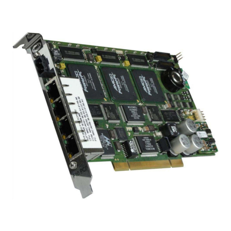
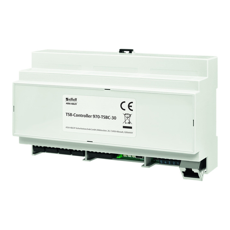
EVOC PCI-16P16R User manual

PCI-16P16R
16 Channels Relay &
Isolated D/I Card

@Copyright 1999-2000 EVOC Technology Co., Ltd.
All Rights Reserved.
The information in this document is subject to change without prior
notice in order to improve reliability, design and function and does
not represent a commitment on the part of the manufacturer.
In no event will the manufacturer be liable for direct, indirect, special,
incidental, or consequential damages arising out of the use or
inability to use the product or documentation, even if advised of the
possibility of such damages.
This document contains proprietary information protected by
copyright. All rights are reserved. No part of this manual may be
reproduced by any mechanical, electronic or other means in any
form without prior written permission of the manufacturer.
Trademarks
PCI-16P16R is registered trademarks of EVOC Co., Ltd. IBM PC is a
registered trademark of International Business Machines Corporation.
Intel is a registered trademark of Intel Corporation. Other product
names mentioned herein are used for identification purposes only
and may be trademarks and/or registered trademarks of their
respective companies.

Contents -i-
Contents
Chapter 1: Introduction...................................................1
1.1 Features...........................................................................2
1.2 Applications .....................................................................2
1.3 Specifications:..................................................................3
Chapter 2: Installation.....................................................5
2.1 What You Have ...............................................................5
2.2 Unpacking .......................................................................5
2.3 PCI-16P16R’s Layout......................................................7
2.4 Jumper and DIP Switch Description................................8
2.5 Input Signal Selection......................................................8
2.6 Connector Pin Assignments .............................................9
Chapter 3: Low-level Programming...........................12
3.1 I/O Port Address Map ...................................................12
3.2 Relay Output Register –Base+00 ..................................13
3.3 Isolated Input Registers.................................................14
3.4 Relay Output.................................................................14
3.5 Programming.................................................................16
Chapter 4: Software User’sManual.............................18
4.1 Version Description.......................................................18

- ii -Contents
4.2 Installation.....................................................................18
4.2.1 Hardware & Driver Installtion...................................................18
4.2.2 Sample Program Installation....................................................19
4.3 ActiveX Control Application Manual ............................20
4.3.1 Application with VC .....................................................................20
4.3.2 Application with VB.....................................................................20
4.4 API DESCRIPTION......................................................21
4.4.1 API for Win98................................................................................21
4.4.2 API for DOS...................................................................................24
Appendix A. Relay Contact Protection Circuits..................26

How to Use This Guide
This manual is designed to help you use the PCI-16P16R. The
manual describes how to modify various settings on the PCI-
16P16R card to meet your requirements. It is divided into four
chapters:
lChapter 1, “Introduction”gives an overview of the product
features, applications and specifications.
lChapter 2, “Installation”describes how to install the PCI-
16P16R. The layout of PCI-16P16R is shown, the DIP
switch setting for base Address, jumpers setting for input
signal, and connectors’pin assignment are specified.
lChapter 3, “Low-level Programming”describes the
register structure and how to program the digital inputs and
outputs on the PCI-16P16R.
lChapter 4,”Software User’s Manual”gives you a software
installation guide and describes the API (application
interface) supplied by PCI-16P16R.
lAppendix A, “Relay Contact Protection Circuits”gives
some circuits for relay contact protection.


Introduction -1-
Chapter 1: Introduction
The PCI-16P16R 16-CH Relay Actuator and Isolated D/I card
is a compact-size and PCI-Bus digital I/O card for IBM
personal computer or compatibles in controlling and sensing
applications.
This card provides 16 relay actuators and 16 opto-isolated
digital inputs. You can use 16 on-board relays to control
power switches or ON/OFF control devices, and use 16 opto-
isolated D/I channels to collect digital inputs in any noisy
environments. It is very essential to use isolated input to
prevent the ground loop problems.
Each relay is matched with one red LED to reflect its ON/OFF
status. Each input channel is jumper selectable to either AC
or DC input control voltage. The isolation voltage is
guaranteed at 1,000V, so that common-mode voltages and
voltage spikes that often occurs in industrial environments
are safety isolated from the PC and the PCI-16P16R.
The digital I/O is via one 37 pins D-type connector that project
through the computer case at the rear of the board.

-2-Introduction
1.1 Features
The PCI-16P16R Relay Actuator and D/I Card provides the
following advanced features:
l32-bit PCI-Bus plug and play
lPlugs directly into the PCI-Bus, do not need accessory
board
l16 relay actuator outputs
l16 opto-isolated AC or DC polarity-free digital inputs
lLEDs to indicate the energized relays
lInput jumpers selectable for AC_Filter/Non-AC_Filter
l1,000 V fully isolation
lOn-board relay driving circuits
lOn-board digital input signal conditioning circuits
l37-pin D-type female connector
1.2 Applications
lIndustrial ON/OFF control
lEnergy management
lExternal high power relay driving, signal switching
lLaboratory automation
lIndustrial automation
lSwitch contact status sensing, limit switch monitoring
lUseful with A/D and D/A to implement a data acquisition &
control system

Introduction -3-
1.3 Specifications:
uRelay Outputs
The 16 electro-mechanical relay outputs are addressed as
two I/O bytes, eight of the relays (outputs 0~4 and 8~12) are
Form C contacts (Normal Open and Normal Closed) and
the remaining relays are Form A (Normal Open only). A LED
indicates each relay’s ON/OFF status for monitoring.
lRelay Type: Double-Pole-Double-Throw (DPDT)
lOutput Channels: 16 (0~4 and 8~12 are Form C; 5~7
and 13~15 are Form A).
lContact Rating: 12VAC/0.5A or 24VDC 1A
lContact Type: Bifurcated
lContact Resistance: 100M Max.
lRelay ON/OFF Time: 5 msec. typical
lCoil Voltage: +12V @33mA for each relay
uIsolated Inputs
The 16 opto-isolated D/I channels are used for sensing
digital inputs and providing 1,000V for isolation. Each
channel can be configured as AC Filter or Non-AC Filter by
jumper settings.
lOpto-Isolator: PC-814
lInput Channels: 16
lInput Signal: AC, don’t care polarity; DC, don’t care
polarity

-4-Introduction
lInput Voltage: 5~24VDC or AC 50~1,000Hz
lInput Impedance: 1.2K
lIsolation Voltage: 1,000V channel-to-channel and
channel-to-ground
lResponse Time: 20 sec without AC Filter, 1ms with AC
Filter
uPower Consumption
l+5VDC: 400 mA typical
l+12VDC: 550mA maximum, all relays are energized
uInterface Characteristic
lI/O Connector: 37-pin Female D-type connector
lCompatible Bus: IBM PC-PCI Bus
uPhysical/Environment
lOperating Temperature: 0 ~60
lStorage Temperature: -20 ~80
lHumidity: 5~90%, non-condensing
lDimension: 173mm(L) 110mm(W)

Installation -5-
Chapter 2: Installation
This chapter describes how to install the PCI-16P16R. At first,
the contents in the package and unpacking information that
you should be careful are described. The jumpers and
switches setting for the PCI-16P16R base address and digital
input configuration (AC signal or DC signal) are also
specified.
2.1 What You Have
In addition to this User’s Manual, the package includes the
following items:
lPCI-16P16R Relay Actuator & Isolated D/I Card
lTwo DB-37 male connectors
l40-pin to DB-37 converter flat cable
If any of these items is missing or damaged, contact the
dealer from whom you purchased the product. Save the
shipping materials and carton in case you want to ship or
store the product in the future.
2.2 Unpacking
Your PCI-16P16R card contains sensitive electronic
components that can be easily damaged by static electricity.

-6-Installation
The card should be done on a grounded anti-static mat. The
operator should be wearing an anti-static wristband,
grounded at the same point as the anti-static mat.
Inspect the card module carton for obvious damage.
Shippingand handling may cause damage to your module.
Be sure there are no shipping and handling damages on the
module before processing.
After opening the card module carton, extract the system
module and place it only on a grounded anti-static surface
component side up.
Again inspect the module for damage. Press down on all
the socketed IC to make sure that they are properly seated.
Do this only with the module place on a firm flat surface.
Note: DO NOT APPLY POWER TO THE CARD IF IT HAS
BEEN DAMAGED.
You are now ready to install your PCI-16P16R

Installation -7-
2.3 PCI-16P16R’s Layout
Figure 2.1: PCI-16P16R layout

-8-Installation
2.4 Jumper and DIP Switch Description
You can change the PCI-16P16R’s input signals by setting
jumpers on the card. The card’s jumpers are preset at the
factory. Under normal circumstances, you should not need
to change the jumper settings.
A jumper switch is closed (sometimes referred to as shorted)
with the plastic cap inserted over two pins of the jumper. A
jumper is open with the plastic cap inserted over one or no
pin(s) of the jumper.
2.5 Input Signal Selection
The PCI-16P16R’s input signal can be selected as either AC
input or DC input signal. There are 2 jumpers (J1 and J9)
associated with each digital input channel for configuring the
channel as AC or DC input. The digital input channels and
their corresponding jumpers are shown in the following
Table 2.3.

Installation -9-
JUMPER INPUT
SIGNAL JUMPER INPUT
SIGNAL
J1 DI0 J9 DI8
J1 DI1 J9 DI9
J1 DI2 J9 DI10
J1 DI3 J9 DI11
J1 DI4 J9 DI12
J1 DI5 J9 DI13
J1 DI6 J9 DI14
J1 DI7 J9 DI15
Table 2.3 The digital input channels and
their corresponding jumper
The default setting of the input signal selection is DC type,
which is shown as below:
Input Signal
Selection AC Input DC Input
(Default)
Jumper
J1~J9 AC position DC position
2.6 Connector Pin Assignments
The PCI-16P16R card comes equipped with two I/O
connectors CON1 and CON2. CON1 is a 37-pin D-type
connector accessible from the rear panel of the card and
CON2 is an on-board 40-pin connector. The pin assignment
of these connectors is described in Figure2.2 and Figure2.3
respectively.

-10-Installation
Figure 2.2 Figure 2.3
Pin Assignment of CON1Pin Assignment of CON2
Legend:
1. DIAn -digital input A of channel n
2. DIBn -digital input B of channel n
3. NCn -normal close pin of relay n
4. Non -normal open pin of relay n
5. COMn -common pin of relay n
6. GND -ground
7. NC -Not Connected
Note: Isolated Digital Input is polarity-free, so you can connect
the digital inputs signal on input A and input B points and
do not care the polarity.

Installation -11-
A cable connector to convert the CON2 40-pin header to
37-pin male D-type connector is enclosed with the PCI-
16P16R. The mapping between the 40-pin header and 37-
pin D-type connector are shown below.
40-pin Ribbon 37-pin D-sub
Figure 2.4 CON2Connection

-12-Low-level Programming
Chapter 3: Low-level Programming
A low-level programming interface of PCI-16P16R is
described in this chapter. If you wish to control the digital
input/output operations through the primitive I/O functions
(inportb and outportb), you have to be careful to understand
the meaning of the structure of the 8 registers. Here, you will
get all detailed information of the PCI-16P16R’s register
format and control procedures.
3.1 I/O Port Address Map
The PCI-16P16R requires 2 consecutive addresses in the PC
I/O address space. The following table (Table 3.1) shows the
location of each register and driver relative to the base
address and its description.
I/O Base
address Read Write
Base+00 Isolated inputs
(DI0~DI15) Relay outputs
(R0~R15)
Base+02 Relay outputs
Status (Read
back)
Table 3.1: The location of register and driver

Low-level Programming -13-
3.2 Relay Output Register –Base+00
The PCI-16P16R provides 16 relay output channels. The
ON/OFF status of each relay is controlled by its
corresponding bit of register, i.e. the control bit is low (0)
status, it turns the relay OFF, and high status (1) will energize
the relay.
The readback capability is also supported in the PCI-16P16R,
i.e. you can read back each relay’s status through Base+02
register.
The relationshipsbetween the bitsof relay output register and
their corresponding relay are shown as below.
Relay Output Register: (Base+00)
Attribute: Write
Data Format:
Bit 76543210
RO7 RO6 RO5 RO4 RO3 RO2 RO1 RO0
Bit 15 14 13 12 11 10 9 8
RO15 RO14 RO13 RO12 RO11 RO10 RO9RO8
RO: Relay Output

-14-Low-level Programming
3.3 Isolated Input Registers.
There are 16 non-polarity isolated inputs provided in the PCI-
16P16R. The register is read-only, as it uses to get status
from input channels.
Isolated Input Register: (Base+00)
Attribute: Read
Data Format:
Bit 76543210
DI7DI6DI5 DI4 DI3 DI2 DI1 DI0
Bit 15 14 13 12 11 10 9 8
DI15 DI14 DI13 DI12 DI11 DI10 DI9DI8
3.4 Relay Output
The PCI-16P16R contains two types of relay: Form C and
Form A. The relay R0~R4 and R8~R12 are form C relays,
and R5~R7 and R13~R15 are form A type. The differences
between these two types of relay are:
1. Form C Relay: (R0~R4 and R8~R12)
Table of contents
Popular Controllers manuals by other brands
Texas Instruments
Texas Instruments TMS320C2000 quick start guide

Kohler
Kohler APM802 installation instructions
Fluidwell
Fluidwell F132-P Operation manual

Biamp
Biamp Qt X installation guide

SIPOS
SIPOS Seven Aktorik Ecotron Series Operation instructions

Franklin Electric
Franklin Electric SubStart SC Assembly and operation instructions
