Doc: MHIT200B1012.docx 20/01/2014 p. 6 / 8
P.09 – Tempo minimo che deve trascorrere fra la disconnessione di uno step e la successiva
riconnessione sia in MAN che in AUT. Durante questo tempo il numero dello step sulla pagina
principale lampeggia.
P.10– Sensibilità alla connessione. Parametro che imposta la velocità di reazione della
centralina. Con valori bassi di P.10 la regolazione è veloce (maggior precisione intorno al
setpoint ma maggior numero di manovre). Con valori alti invece si hanno reazioni più lente
della regolazione, con minor numero di manovre degli step. Il tempo di ritardo alla reazione è
inversamente proporzionale alla richiesta di step per raggiungere il setpoint: tempo attesa =
(sensibilità / numero di step richiesti).
Esempio: impostando la sensibilità a 60s, se viene richiesta l’inserzione di uno step di peso 1
vengono attesi 60s (60/1 = 60) . Se invece servono un totale di 4 step verranno attesi 15s (60 /
4 = 15).
P.11 … P18 – Funzione dei relè di uscita 1…8:
OFF = Non utilizzato
1..32 = Peso dello step. A questo relè è collegato un banco di condenstaori di
potenza n volte (n=1…32) quella del più piccolo, definita con P.06.
ON = Sempre attivato.
NOA = Allarme normalmente disecctato. Il relè si eccita in presenza di un qualsiasi
allarme con la proprietà Allarme globale attiva.
NCA = Allarme normalmente eccitato. Il relè si diseccita in presenza di un qualsiasi
allarme con la proprietà Allarme globale attiva.
FAN = Relè controlla la ventola di raffreddamento.
MAN = Relè eccitato quando centralina è in MAN.
AUT = Relè eccitato quando centralina è in AUT.
A01…A13 = Il relè si eccita in presenza dell’allarme specificato.
P.19 – Setpoint (valore da raggiungere) del cosfi. Utilizato in applicazioni standard.
P.20 - Lingua dei messaggi di allarme scorrevoli.
P.09 - Minimum time that must elapse between the disconnection of one step and the
subsequent reconnection both in MAN or AUT mode. During this time the number of the step
on the main page is blinking.
P.10 - Connection sensitivity. This parameter sets the speed of reaction of the controller. With
small values of P.10 the regulation is fast (more accurate around the setpoint but with more
step swithchings). With high values instead we’ll have slower reactions of the regulation, with
fewer switchings of the steps. The delay time of the reaction is inversely proportional to the
request of steps to reach the setpoint: waiting time = (sensitivity / number of steps required).
Example: setting the sensitivity to 60s, if you request the insertion of one step of weight 1 are
expected 60s (60/1 = 60). If instead serve a total of 4 steps will be expected 15s (60/4 = 15).
P11 ... P18 - Function of output relays 1 ... 8:
OFF = Not used .
1 .. 32 = Weight of the step. This relay drives a bank of cpacitors which power is n
times (n = 1…32) the smallest power defined with parameter P.06.
ON = Always on.
NOA = Alarm normally de-energized. The relay is energized when any alarm with the
Global alarm property arises.
NCA = Alarm normally energized. The relay is de-energized when any alarm with the
Global alarm property arises.
FAN = The relay controls the cooling fan.
MAN = Relay is energized when device is in MAN mode.
AUT = Relay is energized when device is in AUT mode.
A01 ... A13 = The relay is energized when the alarm specified is active.
P.19 - Setpoint (target value) of the cosphi. Used for standard applications.
P.20 - Language of scrolling alarm messages.
.
NOTE: Per i successivi menù vedi manuale completo
scaricabile dal sito
NOTE: For the other menus, refer to the complete instructions
manual available on the website.
Allarmi
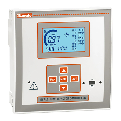
xAl sorgere di un allarme, il display mostra una icona di allarme, un codice
identificativo e la descrizione dell’allarme nella lingua selezionata.
xSe vengono premuti i tasti di navigazione delle pagine, la scritta scorrevole con le
indicazioni di allarme scompare per poi ricomparire dopo 30 secondi.
xIl reset degli allarmi è automatico quando scompaiono le condizioni che li hanno
generati.
xIn seguito al verificarsi di uno o più allarmi, la DCRL ha un comportamento
dipendente dalla impostazione delle proprietà degli allarmi attivi.
Alarms
xWhen an alarm is generated , the display will show an alarm icon, the code and the
description of the alarm in the language selected.
xIf the navigation keys in the pages are pressed, the scrolling message showing the
alarm indications will disappear momentarily, to reappear again after 30 seconds.
xAlarms are automatically resetted as soon as the alarm conditions that have
generated them disappear.
xIn the case of one or more alarms, the behaviour of the DCRL depends on the
properties settings of the active alarms.
Proprietà di default allarmi
Cod.
Descrizione
Abilitazione
Relè allarme
Disconness.
Ritardo interv.
A01 Sottocompensazione 15 min
A02 Sovracompensazione 120 s
A03 Corrente impianto troppo bassa 5 s
A04 Corrente impianto troppo alta 120 s
A05 Tensione impianto troppo bassa 5 s
A06 Tensione impianto troppo alta 15 min
A07 Sovraccarico corrente condensatori 180 s
A08 Temperatura troppo alta 30 s
A09 Microinterruzione 0 s
A10 THD tensione troppo alto 120 s
A11 THD corrente impianto troppo alto 120 s
A12 Richiesta manutenzione 0s
A13 Step difettoso 15 min
Default alarm properties
Cod.
Description
Enable
Alarm relay
Disconnection
Delay
A01 Undercompensation 15 min
A02 Overcompensation 120 s
A03 Current too low 5 s
A04 Current too high 120 s
A05 Voltage too low 5 s
A06 Voltage too high 15 min
A07 Capacitor current overload 180 s
A08 Temperature too high 30 s
A09 No-Voltage release 0 s
A10 Voltage THD too high 120 s
A11 Current THD too high 120 s
A12 Maintenance requested 0s
A13 Step failure 15 min
Installazione
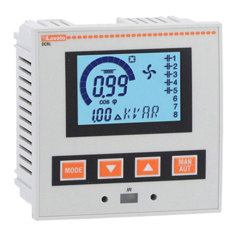
xDCRL è destinata al montaggio da incasso. Con il corretto montaggio garantisce
una protezione frontale IP54.
xDall’interno del quadro, per ciascuna delle quattro clips di fissaggio, posizionare la
clip in una delle due guide laterali, premendo successivamente sullo spigolo della
clip in modo da agganciare a scatto anche la seconda guida.
xSpingere la clip in avanti facendo pressione sulle sue pareti laterali e facendole
scorrere sulle guide fino che le apposite alette deformabili premono al massimo
possibile contro la superficie interna del pannello
Installation
xDCRL is designed for flush-mount installation. With proper mounting, it guarantees
IP54 front protection.
xFrom inside the panel, for each four of the fixing clips, position the clip in one of the
two sliding guide, then press on the clip corner until the second guide snaps in.
xPush the clip forward pressing on its side and making it slide on the guides until it
presses completely on the internal surface of the panel.
