EVOLV DNA 75C User manual
Evolv DNA 75 Color
75 Watt Variable Power Module with Temperature Protection and USB
The DNA 75C is a power regulated digital switch-mode DC-DC converter for personal vaporizers.
It features Evolv’s patented Wattage Control, Temperature Protection, Preheat, a full color TFT screen,
Reverse Polarity Protection, an onboard programmable multicolor LED, waterproof onboard buttons
and a real-time clock. Evolv’s EScribe software and Theme Designer software can be used to fully
customize all aspects of the interface and monitor the user experience. The DNA 75C runs from a single
lithium polymer or lithium ion battery, and features battery monitoring and an integrated 1A charger.
Operating Range
Minimum
Typical
Max
Output Power
1 Watt
75 Watts
Output Voltage
.2 Volts
9.0 Volts
Output Current, continuous
.5 Amps
30.0 Amps
Atomizer Resistance, temperature sensing wire, cold
See Graph
.15 Ohm
See Graph
Atomizer Resistance, Kanthal wire
See Graph
.25 Ohm
See Graph
Temperature Limit
200°F
450°F
600°F
Input Voltage, unloaded
3.0 Volts
3.7 Volts
4.2 Volts
Input Current
12.0 Amps
30.0 Amps
Screen On Current
50mA
Quiescent Current
30mA
Power Down Current
1uA
Efficiency
85%
Specifications
Footprint
.71” x 2.60” / 18mm x 66mm
Thickness
.32”
Screen
.9” 80 x 160 pixel Full Color TFT
Weight
15.2g
Absolute Limits
Minimum
Max
Output Current, instantaneous peak
40.0 Amps
Atomizer Resistance, cold
.02 Ohm
8.0 Ohm
Input Voltage
2.5 Volts
5.0 Volts
Input Current, pulse
32.0 Amps

Contents
Operating Range ........................................................................................................................................... 2
Output Power................................................................................................................................................ 4
Display....................................................................................................................................................... 5
Error Messages ......................................................................................................................................... 5
Charger.......................................................................................................................................................... 6
Battery monitoring.................................................................................................................................... 6
Pinout (bottom side shown) ......................................................................................................................... 6
Wiring............................................................................................................................................................ 7
Recommended wire sizes ......................................................................................................................... 7
Reverse Polarity Protection ...................................................................................................................... 7
External component recommendations ................................................................................................... 7
Assembly ....................................................................................................................................................... 8
Installing the Screen.................................................................................................................................. 8
Mounting....................................................................................................................................................... 9
Mechanical Dimensions .............................................................................................................................. 10
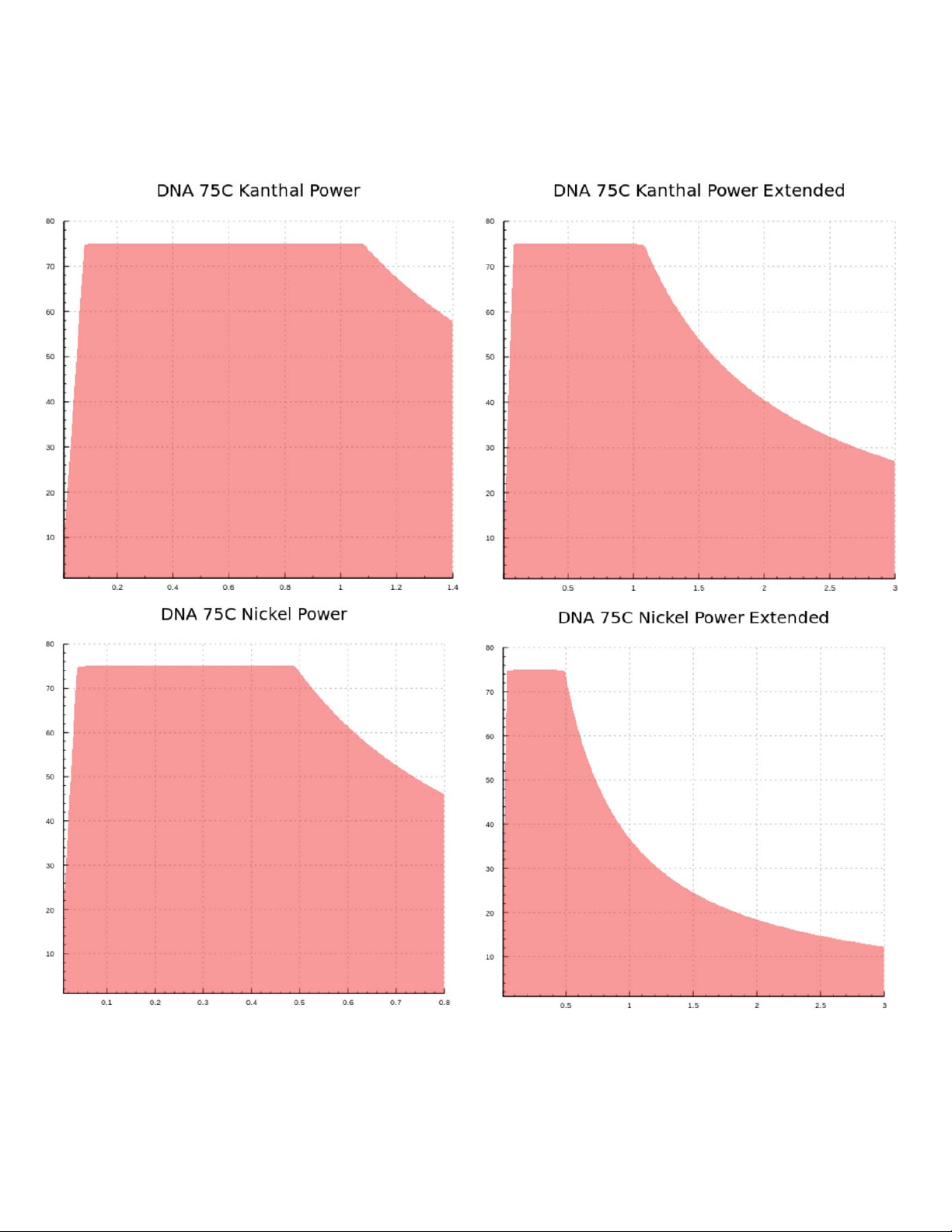
Output Power
The following graphs show the output power range of the DNA 75C as a function of the coil resistance.

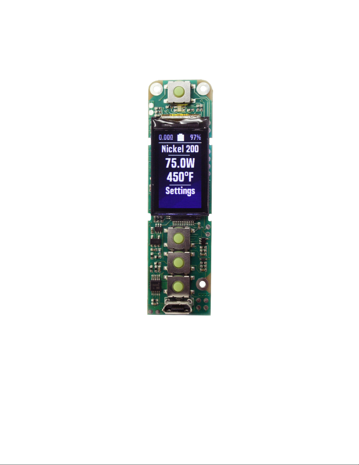
Display
The DNA 75C has a full color 80 x 160 pixel TFT screen. The screen is attached to the main board by a
flexible cable, allowing freedom in the design of your device. The screen’s default position is on top of
the board, between the fire and adjust buttons. This allows for easy assembly. The screen connects to
the board with a ZIF connector, so alternate placement is possible. Please use caution when handling
the screen and design the device so that the cable will be secured or strain relieved in operation. The
two notches along each side of the PCB are designed to accommodate a screen holder. A 3D model is
included with the models on the Evolv website to 3D print or injection mold screen holders for the DNA
75C.
Error Messages
The DNA 75C will indicate a variety of error states.
No Atomizer: The DNA does not detect an atomizer.
Check Atomizer: The DNA does not detect an atomizer, the atomizer has shorted out, or the atomizer
resistance is incorrect for the power setting.
Check Battery: The battery is deeply discharged and needs to be charged, or is damaged. If this
happens, the DNA 75C will not fire the atomizer. The Check Battery message will continue to display for
a few seconds after attempting to fire the device. User should remove and replace the battery.
Shorted: The atomizer or wiring are short circuited.
Ohms Too Low:The resistance of the atomizer coil is too low for the current wattage setting. If this
happens, the DNA 75C will continue to fire, but will not be able to provide the desired wattage. The
Ohms Too Low message will continue to display for a few seconds after the end of puff.
Ohms Too High: The resistance of the atomizer coil is too high for the current wattage setting. If this
happens, the DNA 75C will continue to fire, but will not be able to provide the desired wattage. The
Ohms Too High message will continue to display for a few seconds after the end of puff.
Temperature Protected:The heating coil reached the maximum allowed temperature during the puff. If
this happens, the DNA 75C will continue to fire, but will not be able to provide the desired wattage.
Weak Battery: The battery needs to be charged, or a higher amp rated battery needs to be used. If this
happens, the DNA 75C will continue to fire the atomizer, but will not be able to provide the desired
wattage. The Weak Battery message will continue to display for a few seconds after the end of the puff.
Return To Researcher: The DNA has reached a limit configured by a researcher.
Too Hot:The DNA 75C has onboard temperature sensing. It will shut down and display this message if
the internal board temperature becomes excessive.

Charger
The DNA 75C has a built in 1A USB charger. It automatically detects the type of USB power supply it is
connected to, so it can be plugged into standard PC USB ports or higher power chargers.
Battery monitoring
The DNA 75C contains a full battery management system that continuously monitors the state and
health of the battery both under load and while idle.
Pinout (bottom side shown)
Pin Number
Pin Name
Function
Out
Out
Power output.
1
Fire-
Negative side of the fire button.
2
Fire+
Positive side of the fire button.
3
Up+
Positive side of the up button.
4
Select+
Positive side of the select button.
5
Down+
Positive side of the down button.
6
Logic-
Logic ground. Negative side of the up, select, and down buttons.
Gnd
Gnd
Power output. Gnd is the ground return for the atomizer. It is connected
internally to B-. There are three ground lugs and one ground pad.
B+
B+
Positive battery terminal.
B-
B-
Negative battery terminal. Internally connected to Gnd.

Wiring
The atomizer is connected to the Out pad. If the DNA 75C is not being grounded through the mounting
screws, the Gnd pad should connect to the negative side of the connector. The battery is connected to
the B+ and B- terminals. It is important to use appropriately sized wire when using the DNA. Too small
wire will not perform well, and significantly undersized wire can burn out. The output wires should be
silicone or Teflon insulated only, and at least 14 gauge. The input wire carries less current, and can be as
small as 20 gauge wire if silicone or Teflon insulated.
Recommended wire sizes
Minimum size
Recommended size
Maximum size
Battery, silicone insulated
20 gauge
18 gauge
16 gauge
Battery, PVC insulated
18 gauge
16 gauge
14 gauge
Output, silicone insulated
16 gauge
14 gauge
12 gauge
Switches, if used
28 gauge
24 gauge
22 gauge
Reverse Polarity Protection
The DNA 75C includes built in Reverse Polarity Protection to protect the user, board, device, and battery
in the event that a battery is inserted backwards.
External component recommendations
The DNA 75C is a self-contained power regulator which does not require external buttons for its user
interface. However, it does support the use of external buttons if desired.
Fire button:
Use a momentary on, normally open type switch or button. A standard pushbutton switch is
appropriate. The switch is a logic function – all power switching is handled with transistors inside the
DNA module, so the switch does not need to be rated for power. A waterproof or processed sealed
switch is recommended. Please use caution, as the positive side of the fire button connects directly to
positive battery voltage.
Up/Select/Down buttons:
The small onboard buttons allow the user to navigate the interface and modify device settings.
Alternatively, remote normally open type switches or buttons can be attached to the UP, SELECT and
DOWN mounting holes for customization.
Battery:
The DNA 75C runs from a single lithium polymer type battery pack or round lithium ion 18650 type
battery. The DNA 75C can use multiple cells in a parallel type wiring configuration as long as the
maximum input voltage is 4.2 Volts.

Assembly
Installing the Screen
The TFT screen connects to the DNA 75C using an 8 pin ZIF socket and a flexible cable to allow for design
flexibility. The cable can be bent or folded (once) but care should be taken to not apply tension or strain
to the area where the cable attaches to the screen itself. Once the screen is mounted the cable should
be tucked up under the screen and not out towards the fire button. Positioning the cable near the fire
button can allow the mods fire button to contact the cable when pressed which will cause eventual
screen failure. Only insert or remove the screen before the board is powered on.
Step 1: Locate the ZIF connector on the DNA 75C
PCB.
Step 2: Carefully and gently lift the locking tab on
the rear of the connector to vertical.
Step 3: Fully insert the flexible cable into the front
of the socket with the contact side towards the
PCB.
Step 4: Close the locking tab and press until the
connector gently clicks. Remove the clear screen
protector by pulling on the colored tab.

Screen issues can occur if the screen is inserted incorrectly. If you are experiencing a white screen or
intermittent display issues confirm the screen is correctly seated in the ZIF socket as shown below.
Mounting
The DNA 75C has onboard switches for adjusting the power level, navigating the interface and activating
the output. Each of these functions also has optional through-hole pads for using remote buttons.
The DNA 75C has three mounting holes on the PCB. These holes are designed for #0 screws. There is an
extended mounting pad of .125” diameter around each. These holes are electrically connected to each
other and to ground. With careful design, the mounting pads can be used to ground the chassis to the
DNA 75C, and pass the output current through chassis to the connector. However, if using this method,
ensure that the PCB remains in good contact with the board at all times. Split lock washers and a RoHS
chromate conversion coating on the chassis are recommended.
It is recommended that DNA boards be secured using the provided holes to mechanically mount them to
the device. Use of glues are not suggested including hot glue, epoxy, superglue, hobby cement, etc. The
only adhesive approved for contact with the board is non-corrosive Silicone adhesive such as the kind
available from MG Chemicals.
DNA boards are complex, utilizing multilayer PCBs, and are designed with safety and reliability in mind.
Please do not modify components on the boards, remove onboard buttons, shave, cut or trim the PCB
or enlarge the mounting holes. Doing so creates the potential to expose layers in the PCB and could
cause a safety and/or reliability issue. Evolv reserves the right to deny a warranty claim for any and all
board modifications or improper use.
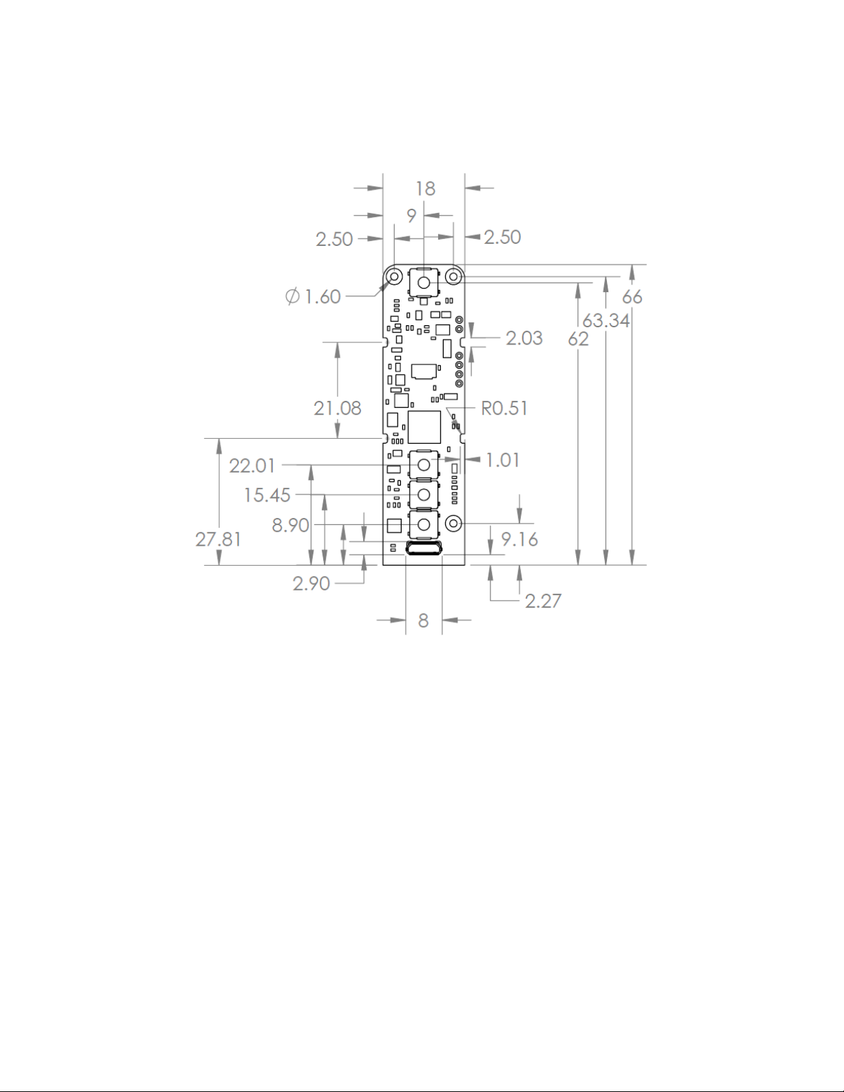
Mechanical Dimensions
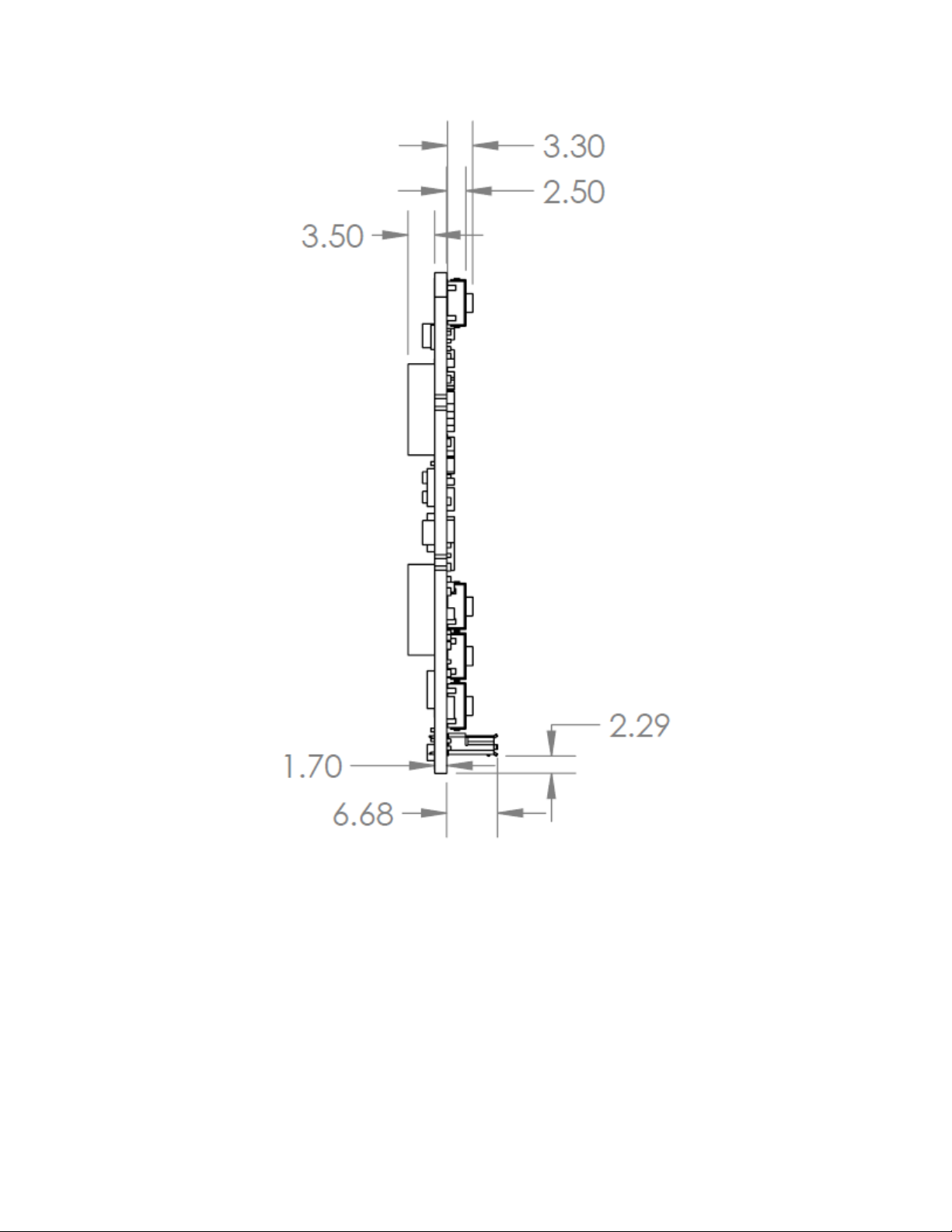

3D models of the DNA 75C available on our website in IGES, STEP, and Solidworks formats.
Table of contents
Popular Media Converter manuals by other brands


Microflex
Microflex 101-0019 Installation Operation & Specifications Manual

Buffalo
Buffalo AirStation WLI3-TX1-G54 user manual

Lenz
Lenz 10133 Information

Extron electronics
Extron electronics CLK 100 user guide

TR-Electronic
TR-Electronic Profibus 802 Series user manual

tams elektronik
tams elektronik LD-G-2 manual


