Information LE130XF/LE131XF
Seite 2von 6/ Page 2of 6
hierdurch wird die notwendige Luftzirkulation um den
Empfänger verhindert. Kleben Sie vielmehr die Metallteile der
Lokomotive mit Isolierband o.ä. ab. Hierdurch können Sie
ungewollte Kurzschlüsse vermeiden, ohne daß der Empfänger
'erstickt'.
Der Schrumpfschlauch, der sich über einem Teil des
Lokempfängers befindet, schützt berührungsempfindliche Teile
und darf daher nicht entfernt werden. Fixieren Sie den
Empfänger mit doppelseitigem Klebeband.
Mit Digital plus Decodern ausgerüstete Lokomotiven dürfen
auf Zweileiteranlagen nicht an der Oberleitung betrieben
werden, da die Lokomotive durch Aufgleisen in der falschen
Richtung die doppelte Fahrspannung erhalten kann. Hierbei
wird der Lokempfänger zerstört!
Alle Ausgänge des Empfängers werden von einer internen
Gleichrichterschaltung versorgt, die einen maximalen
Gesamtstrom von 1,0 A zuläßt. Es darf also die Summe aller
an Motor und Funktionsausgängen auftretenden Ströme nie
größer sein als dieser zulässige Gesamtstrom. Jeder
Einzelausgang darf nur bis zu seinem zulässigen
Maximalstrom belastet werden.
Rechnerisch ist zwar die Summe der beiden Maximalströme
von Motor und Funktionsausgang größer als der zulässige
Gesamtstrom von 1,0 A, dennoch darf dieser Wert im
Dauerbetrieb nicht überschritten werden
Bevor Sie einen Digital plus Lokempfänger einbauen:
Prüfen Sie die Lokomotive vor dem Umbau im normalen
Gleichstrombetrieb auf einwandfreie Funktion. Ersetzen Sie
verschlissene Kohlen und durchgebrannte Birnchen. Nur eine
Lok mit einwandfreier Mechanik kann mit einem Lokempfänger
einwandfrei fahren. Kondensatoren über den
Motoranschlüssen müssen entfernt werden.
metal components of the locomotive. By doing so you can
avoid unintentional short-circuits without depriving the decoder
of air.
The heat-shrink sleeve covering parts of the locomotive
decoder protects components which are sensitive to contact
and therefore it is not to be removed. Use double-sided
adhesive-tape to affix the decoder.
Locomotives equipped with Digital plus decoders must not be
run using powered overhead line either on conventional DC
control or DCC control This could subject the locomotive to
double the voltage and this would destroy the decoder.
All decoder outputs are supplied by an internal rectifier that
permits a maximum current of 1.0 A. Therefore the sum total of
all currents from functional inputs and outputs must not exceed
the permitted total current. No individual output may be loaded
beyond its permitted maximum current.
Although the sum of the specified maximum currents of both
motor and function outputs is larger than the permitted
1000mA, nevertheless, in continuous operation this value of
1000mA must not be exceeded.
No bulbs may be connected if the motor itself requires a
current of 1000mA.
Before installing a Digital plus Decoder:
Check the loco in normal DC operation to make sure that it
works as it should before modifying the locomotive.
Replace worn wheel contacts, motor brushes and blown bulbs.
Only a locomotive that is mechanically OK will function
properly with a locomotive decoder. Capacitors across the
motor connections must be removed.
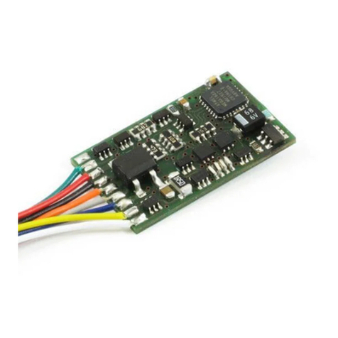
Einbau des LE130XF
Notieren Sie sich, welcher Motoranschluß mit den rechten und
welcher mit den linken Radschleifern verbunden ist. Dies
erspart Ihnen beim Anschluß des Lokempfängers Versuche,
welches Kabel des Lokempfängers an welchen Motoranschluß
gelötet werden muß, um die richtige Fahrtrichtung einzustellen.
Die Motoranschlüsse müssen nach Entfernen der bisherigen
Kabel potentialfrei sein. Das heißt, sie dürfen keine
Verbindung zum Chassis oder den Lokrädern (Radschleifern)
mehr haben. Achten Sie auch darauf, daß solche
Verbindungen mitunter erst durch Aufsetzen des Gehäuses
entstehen können!
Wenn Sie sich nicht sicher sind, ob alle Voraussetzungen zum
Einbau erfüllt sind, wenden Sie sich an einen Servicebetrieb
Schließen Sie den Lokempfänger zuerst an die Radschleifer
an:
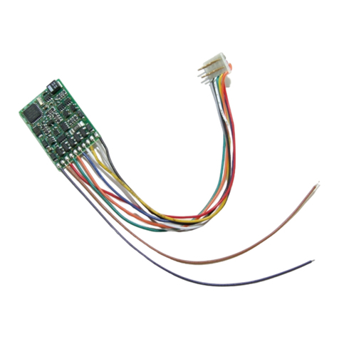
•rotes Kabel an die in Fahrtrichtung rechten Radschleifer
•schwarzes Kabel an die in Fahrtrichtung linken
Radschleifer.
Dann verbinden Sie den Empfänger mit den
Motoranschlüssen:
•oranges Kabel an den Motoranschluß, der vorher mit den
rechten Radschleifern verbunden war
•graues Kabel an den Motoranschluß, der vorher mit den
linken Radschleifern verbunden war.
Nun schließen Sie die Funktionen an. Im Auslieferungszustand
sind diese Funktionsausgänge wie folgt eingestellt: Ausgänge
A und B reagieren fahrtrichtungsabhängig auf F0, die
Ausgänge C und D reagieren auf F1 und F2. Diese Einstellung
kann geändert werden.
Wenn Sie die Funktionsausgänge in der Werkseinstellung
Installation of the LE130XF
Take note of which motor connection is linked to the right-hand
locomotive wheels and which to the left. If you do this you will
not have to try out which cable of the decoder needs to be
soldered to which connection of the motor in order to achieve
the desired direction of travel.
After the removal of the original connections to the motor
brushes, both the motor brushes must be potential free and
completely isolated from both tracks. This means that they
must not be connected in any way to the chassis or to the
wheels of the locomotive. Also bear in mind that such
connections are sometimes created only when the chassis is
put back!
Please contact a service centre if you are in any doubt as to
whether all preconditions for the installation are fulfilled!
First connect the decoder to the pick-ups from the wheels of
the locomotive:
•red cable to the wheels which in relation to the direction of
travel are on the right-hand side of the locomotive
•black cable to the wheels which in relation to the direction
of travel are on the left-hand side of the locomotive
Then connect the decoder to the motor connections:
•orange cable to the motor connection previously
connected to the right-hand locomotive wheels
•grey cable to the motor connection previously connected
to the left-hand locomotive wheels.
Now connect the functions. Ex-works default settings for the
functions are configured as follows: function outputs A and B
as direction-dependent outputs reacting to F0, function outputs
C and D react to F1 and F2. This configuration can be altered
as desired.
