NSK EDD Megatorque Motor User manual
MEGATORQUE MOTORTM SYSTEM
User’s Manual
(Driver Unit Model EDD)
Document Number: C20201-01
M-E099DD0C2-201

Limited Warranty
NSK Ltd. warrants its products to be free from defects in material and/or workmanship which NSK
Ltd. is notified of in writing within, which comes first, one (1) year of shipment or 2400 total
operation hours. NSK Ltd., at its option, and with transportation charges prepaid by the claimant,
will repair or replace any product which has been proved to the satisfaction of NSK Ltd. to have a
defect in material and/or workmanship.
This warranty is the sole and exclusive remedy available, and under no circumstances shall NSK
Ltd. be liable for any consequential damages, loss of profits and/or personal injury as a result of
claim arising under this limited warranty. NSK Ltd. makes no other warranty express or implied,
and disclaims any warranties for fitness for a particular purpose or merchantability.
Copyright 2019 by NSK Ltd., Tokyo, Japan
All rights reserved.
No part of this publication may be reproduced in any
form or by any means without permission in writing
from NSK Ltd.
NSK Ltd. reserves the right to make changes to any
products herein to improve reliability, function or design
without prior notice and without any obligation.
NSK Ltd. does not assume any liability arising out of the
application or use of any product described herein;
neither does it convey any license under its present
patent nor the rights of others.

Notes for Proper Use of Megatorque Motor System
1. For Safety Use of the Products
This product is intended for the uses of general industry, and is not designed and/or manufactured for the uses
involving human lives.
When you consider to use this product for special uses such as nuclear control, aero-space devices, traffic control,
medical devices, various safety devices or such systems, please contact us.
Although this product is manufactured under strict quality control, be sure to provide safety equipment for
applications to the facility which can cause serious accidents or losses due to the failure of this product.
2. Precautionary statement for the prolonged use of the Driver Unit
1) Temperature
Keep the ambient temperature of the Driver Unit within 0 to 50[°C]. You cannot use the Driver Unit in a high
temperature atmosphere over 50[°C]. Keep a clearance of 100 mm in the upper and the lower side of the Driver Unit
when it is installed in an enclosure. If heat is built up on the upper side of the Driver Unit, provide ventilation openings
on the top surface or equip a forced air cool unit to take the heat out of the Driver Unit. (Measures against contamination
are required for the ventilation openings.)
2) Dust-proof and Waterproof
Put the Driver Unit in an enclosure with the protection code of IP54 or better. Protect the Driver Unit from oil-mist,
cutting oil, metal chips and paint fume, etc. Otherwise it may result in failure of electric circuits of the Driver Unit.
(The IP code is to specify the protection level of enclosures from solid contamination and water. It is specified in the
IEC standard and other safety regulations.)
3) Wiring/Ground
Refer to the User's Manual for proper wiring.
When wiring and installing the Driver Unit, take appropriate measures not to contaminate it.
Use the product by adhering to power specifications of Driver Unit.
For IO cable of CN2 control, use the one with cable length shorter than 2[m].
For CN0 USB communication cable, use the double-shielded one with length shorter than 3[m], and for the connector
at Driver Unit side, use USB mini-B.
4) Storing
Store the Driver Unit in a place at where it is not exposed to rain, water, and harmful gas or liquid.
Store the Driver Unit in the place at where it is not exposed to direct sunlight. Keep the ambient temperature and the
humidity as specified.
5) The limited number of times for overwriting data to EEPROM.
The EEPROM is used to backup all data and programs. However, the number of times for overwriting is limited to
approximately 100 000 times.

3. Precautionary statement for the prolonged use of the Motor
1) Temperature
Keep the ambient temperature of the Motor within 0 to 40[°C]. You cannot use the Motor in a high temperature
atmosphere over 40[°C].
2) Dust-proof and Waterproof of the Motor
The standard Motors PS series/PN series/PX series are not made for dust-proof or waterproof (IP30 equivalent).
You cannot use the Motor in humid or oily atmosphere.
3) Use conditions
The allowable moment load and axial load depend on the Motor size. Double check the specified limits of the Motor
meet the actual use conditions.
An excessive load or excessive offset load will cause permanent deflection of the rotor and the bearing abnormality.
Be sure not to drop the Motor or not to give an excessive impact to it while transporting it or installing it.
The flatness of the Motor mounting surface shall be 0.02 mm or less.
4) Periodic check
Puncture of the Motor and shorting or breakage of cable may occur depending on using and environmental conditions.
If the Motor is left in such conditions, it cannot exhibit its capability 100 % and will lead to a problem of the Driver
Unit. We recommend conducting the periodic preventive measures such as an insulation resistance check of the Motor,
to see its current condition.

4. Quick troubleshooting …Confirm it one more time.
1) When an alarm occurs
When an alarm occurs right after the power is on, please refer to
4.1. Quick Troubleshooting…Alarm when the power is on .
Did you take proper action to the alarm?
◊Follow the remedy described in the manual again.
2) When the power does not turn on and the indication display does not turn on
Check the voltage of main and control power by a tester if the voltage is in the range of specifications that are described
in the User’s manual.
3) When the Motor does not move
Turn off the Motor power and check the followings.
Does the Motor turn smoothly?
Is there any jerky motion?
Does the rotation axis have any axial play?
(Never disassemble the Motor.)
Are the control Inputs and Outputs properly functioning?
◊Monitor the status of SVON and IPOS signals by the I/O command through the Handy Terminal.
◊Check if the voltage of input signal and 24 VDC power source are stable using an oscilloscope, etc.
4) The Motor vibrates. Positioning is inaccurate. Alarm of software thermal occurs frequently.
Did you tune the servo parameters LO (Load inertia), SG (Servo gain), VG (Velocity loop proportional gain), PG
(Position loop proportional gain), FP (Primary low-pass filter) and NP (Primary notch filter)?
◊Apply tuning to servo parameters by referring to “5. Tuning.”
Are the fixing bolts of the load and the Motor securely fastened?
◊Check and fasten them tightly if necessary.
Connect the ground terminal of the Driver Unit to one point grounding. (Refer to the User’s Manual for wiring.)
Is any external force in rotational direction when the Motor is stopping with the Servo lock state? (It leads to the Motor
overheat if external force is applied.)
5) Breaker trip occurs frequently.
When the System recovers from the breaker trip by turning on the power again, take the following action.
◊Select a breaker of which rated current suits to the power capacity of the Driver Unit.
4.1. Quick Troubleshooting…Alarm when the power is on
The alarm occurs when the power is turned on if input signals of EMST (Emergency stop, Pin No.3) and OTP/OTM
(Over travel limits, Pin No. 5 and 6) of the connector CN2 are not connected.
However, the Driver Unit is not defective.
◊This is because the ports of EMST input and OTP/OTM inputs are set to the normally closed contact (B contact) at the
factory.
To cancel the alarm, wire these ports or follow the procedure below to change the polarity to the normally open contact
(A contact).
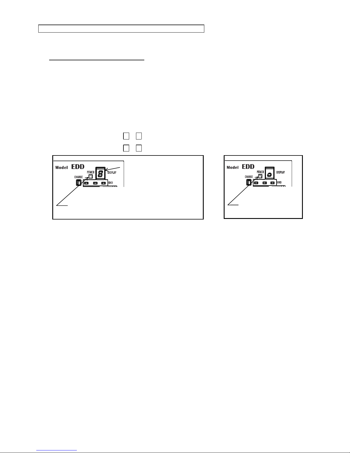
Step 1: identify the alarm.
1) Turn on the power of the Driver Unit.
2) Check the 7 segments LED on the front panel of the Driver Unit.
◊The LED changes in order of F →4 in case of “Emergency stop.”
◊The LED changes in order of F →3 in case of “Travel limit over”alarm.
Power LED:Turns on after the power is on. .
Normal: Green
Abnormal: Orange
7segments LED: Identifies a type of alarm.
It indicates a type of alarm in 2 digit
numbers. The numbers will be dispalyed in
time sharing.
If two or more errors occurs, the LED
indicates them in the same manner as
described above.
Powe LED: Turns on after the power is on.
Normal: Green
Abnormal: Orange
When an alarm occurs
In normal state

Step 2: Polarity setting of Input ports.
1) Input the command MO (Motor Off) to make the
Motor servo off to set the polarity of control
inputs.
O
ENT
M
:MO
:_
2) Input the command PI0 (Edit input function).
:PI0
FNEMST;_
I
ENT
0 ?
P
3) Following the display of the parameter FN
(Function), the parmaeters NW (Anti-chattering
timer) AB (Input polarity) appear sequentially by
a press of SP key, then the prompt “?”appears
on the bottom line.
FNEMST;
AB1;
NW0.2
?_
SP
SP
◊SP key operation is not necessary in the terminal screen of EDD MegaTerm. After operating (2) above, proceed to
operation (4).
4) Input the paramter AB0 to change the polarity to
the normally open contact.
After the imput, a prompt “?”appears again,
press the ENT key when the prompt “?”
appears again.
Thus the input EMST is set to the normally open
contact.
?AB0
?
:_
ENT
B
A
ENT
0 ?
5) Input the command SV (Servo on) to turn on the
servo of the Motor..
:SV
:_
V
S
ENT
◊When setting the input OTP to the normally closed contact, input the command PI2 and follow the procedure above.
◊When setting the input OTM to the normally closed contact, input the command PI3 and follow the procedure above.
5. Others
Combination of the Motor and the Driver Unit shall conform to the specification.
Be sure to keep the record of parameter settings.
Do not modify the cable set.
Lock the connectors securely and check for loose fixing screw(s).
Please keep expendable parts and backup parts. (The Motor, the Driver Unit and the Cable set for replace)
Use alcohol for cleaning, and never apply thinner.

(Blank Page)

Conformity with the International Safety Regulations
The Megatorque Motor Systems conform to the EU Directives (CE Marking) and Underwriters Laboratory (UL) regulations.
Conformity with the EU Directives
The Megatorque Motor System is a machine component that conforms to provisions of the Low Voltage Directive
2014/35/EU and EMC Directives 2014/30/EU. This will help a user in easy conformity with the EU Directives (CE
marking) of a machine into which the Megatorque Motor System is incorporated.
Table 1: List of compliance standard
Item
Conformed regulation
Megatorque
Motor
EN60034-1
: Rotating electrical machines
Low Voltage
Directive
Motor /
Driver Unit
EN61800-5-1
: Adjustable speed electrical power drive
systems
EN55011
: Conducted emission(Group1, Class A)
Electromagnetic
Compatibility
Directive
EN55011
: Radiated emission(Group1, Class A)
EN61000-6-4
: Emission standard for industrial
environments
EN61000-6-2
: Immunity for industrial environments
EN61800-3
: EMC requirements and specific test
methods (Emission: Category C2)
(Immunity: Second environment)
EN61000-4-2
: Electrostatic discharge immunity
EN61000-4-3
: Radiated electromagnetic field immunity
EN61000-4-4
: Electric first transient/ burst immunity
EN61000-4-5
: Surge immunity
EN61000-4-6
: Conducted disturbance immunity
EN61000-4-8
: Power frequency magnetic field immunity
EN61000-4-11
: Voltage Dips & Interruptions immunity
Warning In a domestic environment, this product may cause radio interference, in which case
supplimentary mitigation measures may be required.
Conformity with EMC Directive
NSK defined installation models (conditions) for the Megatorque Motor PS/PN Series, including installation space and
wiring between Driver Units and Motors, and set EMC Directive based on 4 [m] cable models, which have been
certified by TÜV SÜD Product Service GmbH.
When Megatorque Motor PS/PN Series is incorporated into machinery, real-world installation and/or wiring conditions
may differ from those of established models. Therefore, it is necessary to check for EMC Directive compliance
(especially radiation and conduction noise) in the machinery incorporating the PS/PN Series Motors.

Conditions to Conform with EU Directives
The wiring example shown below is one of our recommendations for the conformity with the EU Directives.
Figure 1: Wiring diagram (Example)
Surge
absorber
Resolver
AC power
source
Protective
ground (PE)
Main
power
CN5
Control
power
CN4
CN3
L
N
L
N
CN1
Handy
Terminal
Ferrite
core 1
(3 turns)
Ferrite
core 3
(1 turn)
Ferrite
core 3
(1 turn)
Ferrite
core 3
(2 turns)
MegatorqueMotor
Ferrite
core 2
(2 turns)
Motor
Driver Unit Model EDD
Inside of control panel
Circuit breaker
Noise filter
Environmental conditions
The Driver Unit must be used in the environmental condition of Pollution Degree1 or 2 as specified by
IEC60664-1. The Driver Unit shall be installed into a control panel with the structure that does not allow
penetration of water, oil or dust (IP54).
Power source
The Driver Unit Model EDD shall be used in the environmental condition of “Over-voltage category III”
as specified by IEC60664-1.
Circuit breaker
Install a circuit breaker that conforms to IEC standard and UL safety standard between the power source
and the Driver Unit.
Noise filter
Install a noise filter between the power source and the Driver Unit.
Ferrite core
Ferrite cores for signal cable shall be set to the power cable, the Motor cable and the resolver cable.
Protective Grounding
Be sure to ground the protective grounding terminal of the Driver Unit Model EDD to the protective
ground (PE) of the control panel for a measure against electrical shock.
Table 2: List of recommended parts
Item
Specification
Model Number
Remarks
Circuit breaker
Rated current:
15 [A]
BW32AAG
(Fuji Electric)
Conforms to IEC regulations and
approved by UL
Noise filter
Single phase:
250 [VAC], 10 [A]
FN2070-10/06
(SCHAFFNER)
Surge absorber
–
R-A-V781BWZ-4
(Okaya electric)
Ferrite core 1
–
E04RA400270150
(Seiwa Electric MFG)
Ferrite core 2
–
E04SR301334
(Seiwa Electric MFG)
For the Terminal
Ferrite core 3
–
E04SR211132
(Seiwa Electric MFG

Conformity with Underwriters Laboratories Standards
Motors
Motor is compliant with UL1004-1 standard. (File number:E216970)
Driver Unit Model EDD
Driver Unit Model EDD is compliant with UL61800-5-1 standard. (File number:E216221)
Cable set
The cable material which is conforming to UL standard is used.
Be sure to meet the following as they are the supplementary conditions for the qualification.
Environmental conditions
The Driver Unit must be used in the environmental condition of Pollution Degree1 or 2 as specified
by IEC60664-1.
The Driver Unit shall be installed into a control panel with the structure that does not allow
penetration of water, oil or dust (IP54).
Power source
The Driver Unit Model EDD shall be used in environmental condition of “Over-voltage category III” as
specified by IEC60664-1.
Suitable for use on a circuit capable or delivering not more than 5,000[Arms] symmetrical amperes, 240[V]
maximum.
Circuit breaker
Install a circuit breaker (rated 15[A]) that conforms the UL safety standard between the power source
and the Driver Unit. (Please refer to Table 2 above for the specifications.)
Protective Grounding
Be sure to ground the protective grounding terminal of the Driver Unit Model EDD to the protective ground
(PE) of the control panel for a measure against electrical shock.
Wiring
・Use 75 [C] CU wire only.
・Wire range for field wiring terminals are marked adjacent to the terminal, on the wiring diagram or
instruction manual.
Table 3: Acceptable lead diameter
Model No.
Wire Range(AWG)
Input
Output
All Models
18
19
Others
・Solid state Motor overload protection level of 115 [%] of FLA is provided in each model.
・Integral solid state short circuit protection does not provide branch circuit protection. Branch circuit
protection must be provided in accordance with the National Electrical Code and any additional local
codes.
・Motor over temperature protection is not provided by the driver unit.

!
Danger :Megatorque Motor PN series with Brake unit, Megatorque Motor Z
series with High environmental resistance, Megatorque Motor High
speed PX series with its Driver Unit, and their system as a combination
of Motor and Driver Unit do not comply with UL and CE marking
regulation. Driver Units comply with UL Standard and CE Mark when
used with a standard PN series Megatorque Motor. However, they do
not comply with UL standards or CE Mark when used with Megatorque
Motor PN series with Brake unit and Megatorque Motor Z series with
High environmental resistance.
!
Caution : Risk of Electric Shock- Capacitor discharge time is at least 5 [min]

—i —
Contents
1. Introduction ------------------------------------1-1
1.1. Notes to Users---------------------------------------------1-2
1.1.1. Notes for Safety-----------------------------------1-2
1.1.2. Precautions for Use------------------------------1-2
1.1.3. Interchangeability of Motor and Driver Unit 1-5
1.2. Terminology ------------------------------------------------1-6
2. Specifications ---------------------------------2-1
2.1. System Configuration ------------------------------------2-1
2.1.1. Control Mode --------------------------------------2-1
2.1.2. Examples of System Configuration ----------2-2
2.2. Reference Number and Coding -----------------------2-4
2.2.1. Mega torque Motor-------------------------------2-4
2.2.2. Driver Unit Model EDD--------------------------2-4
2.2.3. Cable Set -------------------------------------------2-4
2.2.4. Handy Terminal -----------------------------------2-4
2.3. Name of Each Part----------------------------------------2-5
2.3.1. Mega torque Motor-------------------------------2-5
2.3.1.1. PS Series ------------------------------------2-5
2.3.1.2. PN Series ------------------------------------2-6
2.3.1.3. PX Series ------------------------------------2-7
2.3.2. Driver Unit Model EDD--------------------------2-8
2.3.3. Handy Terminal -----------------------------------2-9
2.4. Standard Combination List----------------------------2-10
2.4.1. Motor and Driver Unit Model EDD
Combinations------------------------------------2-10
2.4.2. Cable Set -----------------------------------------2-11
2.4.3. Handy Terminal ---------------------------------2-11
2.5. Motor Specifications------------------------------------2-12
2.5.1. PS Series-----------------------------------------2-12
2.5.2. PN Series-----------------------------------------2-13
2.5.3. PX Series -----------------------------------------2-13
2.5.4. Axial Load and Moment Load ---------------2-14
2.6. External Dimensions -----------------------------------2-15
2.6.1. Megatorque Motors ----------------------------2-15
2.6.1.1. PS Series ----------------------------------2-15
2.6.1.2. PN Series ----------------------------------2-19
2.6.1.3. PX Series ----------------------------------2-21
2.6.2. Driver Unit Model EDD------------------------2-22
2.6.3. Cable Set -----------------------------------------2-23
2.6.3.1. Stationary Cable--------------------------2-23
2.6.3.2. Flexible Cable-----------------------------2-23
2.7. Driver Unit Specifications -----------------------------2-25
2.8. USB Interface Specifications-------------------------2-27
2.8.1. CN0: USB Communication Connector ----2-27
2.8.1.1. Pin-Out (CN0)-----------------------------2-27
2.8.1.2. CN0 Signal List---------------------------2-27
2.9. RS-232C Interface Specifications-------------------2-28
2.9.1. CN1: RS-232C Serial Communication
Connector-----------------------------------------2-28
2.9.1.1. CN1 Pin-Out-------------------------------2-28
2.9.1.2. CN1 Signal List---------------------------2-28
2.10. Specifications of Control Input/Output Interface2-29
2.10.1.CN2: Control Input/Output Signal
Connector-----------------------------------------2-29
2.10.1.1. CN2 Pin-Out -----------------------------2-30
2.10.1.2. CN2 Signal List ------------------------- 2-31
2.10.2.CN2 Interfacing --------------------------------- 2-33
2.10.2.1. General Input Signal------------------- 2-33
2.10.2.2. Pulse Train Input Signal -------------- 2-34
2.10.2.3. Analog Command Input Signal ----- 2-35
2.10.2.4. Output Signal---------------------------- 2-36
2.10.2.5. Position Feedback Signal Output -- 2-36
2.10.2.6. Analog Monitor Output---------------- 2-37
2.11. CN3: Resolver Cable Connector------------------ 2-38
2.11.1.CN3 Pin-Out------------------------------------- 2-38
2.11.2.CN3 Signal List --------------------------------- 2-38
2.12. CN4: Motor Connector------------------------------- 2-39
2.12.1.CN4 Pin-Out------------------------------------- 2-39
2.12.2.CN4 Signal List --------------------------------- 2-39
2.13. CN5: Connector for Power Supply --------------- 2-40
2.13.1.CN5 Pin-Out------------------------------------- 2-40
2.13.2.CN5 Wiring Diagram--------------------------- 2-40
3. Unpacking, Installation and Wiring ------3-1
3.1. Unpacking -------------------------------------------------- 3-1
3.1.1. Receiving Check---------------------------------- 3-1
3.1.2. Motor and Driver Unit Model EDD
Combinations-------------------------------------- 3-1
3.2. Installation -------------------------------------------------- 3-2
3.2.1. Motor Mounting -----------------------------------3-2
3.2.1.1. Environmental Conditions of Motor --- 3-2
3.2.1.2. Motor Installation--------------------------- 3-2
3.2.1.3. Coupling Load to Motor ------------------3-3
3.2.1.4. Confirmation of Use Conditions--------3-4
3.2.1.5. Dummy Inertia------------------------------ 3-4
3.2.2. Installation of Driver Unit -----------------------3-5
3.3. Wiring--------------------------------------------------------3-6
3.3.1. Connection of Cable Set------------------------3-6
3.3.2. Connecting Power-------------------------------- 3-7
3.3.3. Ground Connection------------------------------ 3-8
3.3.4. Connector Wiring--------------------------------- 3-9
3.3.4.1. Wiring Example (CN2)-------------------- 3-9
3.4. Turning on Main Power-------------------------------- 3-10
3.4.1. Precautions Before Power-on--------------- 3-10
3.4.2. Points to be Checked When Power-on --- 3-11
3.4.3. Polarity Setting of Control Input Port
(Normally Open Contact and Normally
Closed Contact)--------------------------------- 3-12
3.4.4. Power on and Servo on----------------------- 3-13
4. RS-232C Communication and USB
Communication-------------------------------4-1
4.1. RS-232C Communication
(Handy Terminal Communication)-------------------- 4-2
4.1.1. Check on Handy Terminal ---------------------- 4-3
4.1.2. Setting Parameters ------------------------------- 4-3
4.1.2.1. Input of the Password --------------------4-3
4.1.2.2. Reset to Shipping Set --------------------4-4
4.1.3. Readout of Parameter---------------------------4-4
4.1.3.1. Monitoring Parameters by a Group --- 4-5
4.1.3.2. Monitoring Parameters Altered from
Shipping Set -------------------------------- 4-5

—ii —
4.1.4. Monitoring the Current Status ------------------4-6
4.1.4.1. Inputting a Command while
Monitoring Multiple Conditions----------4-6
4.2. USB Communication (EDD MEGATERM)----------4-7
4.2.1. Setting Application Software--------------------4-9
4.2.2. Establishing Communication------------------4-10
4.2.3. Setting Parameters------------------------------4-10
4.2.3.1. Input of the Password-------------------4-11
4.2.3.2. Reset to Shipping Set-------------------4-12
4.2.4. Readout of Parameter--------------------------4-12
4.2.4.1. Monitoring Parameters by a Group--4-13
4.2.4.2. Monitoring Parameters Altered from
Shipping Set-------------------------------4-14
4.2.5. Monitoring the Current Status ----------------4-14
4.2.5.1. Inputting a Command while
Monitoring Multiple Conditions--------4-15
5. Tuning-------------------------------------------5-1
5.1. Tuning Flowchart------------------------------------------5-1
5.2. Tuning Level 1: Automatic Tuning --------------------5-2
5.2.1. Precautions for Automatic Tuning-------------5-3
5.2.2. Initialization of Servo Parameters -------------5-4
5.2.3. Automatic Tuning----------------------------------5-5
5.2.4. Trial Running----------------------------------------5-7
5.3. Tuning Level 2: Servo Gain Tuning-------------------5-9
5.3.1. Input of Load moment of Inertia----------------5-9
5.3.1.1. When the Load moment of inertia is
Unknown -------------------------------------5-9
5.3.2. Minor Tuning of Servo Gains -----------------5-10
5.4. Tuning Level 3: Manual Tuning----------------------5-13
5.4.1. Precautions for Manual Tuning---------------5-13
5.4.2. Setting Velocity Loop Proportional Gain (VG)5-13
5.5. Setting Filters (Tuning Level 2)----------------------5-15
5.5.1. Setting Low-pass Filter-------------------------5-15
5.5.2. Setting Notch Filter------------------------------5-16
6. Operation---------------------------------------6-1
6.1. Preparation -------------------------------------------------6-1
6.1.1. Wiring Check----------------------------------------6-1
6.1.2. Operation Procedure------------------------------6-1
6.2. Position Scale----------------------------------------------6-2
6.2.1. Resolution of position Scale --------------------6-2
6.2.2. Direction of Position Scale ----------------------6-3
6.2.3. Setting Home Position----------------------------6-4
6.2.4. Software Over Travel Limit----------------------6-6
6.2.4.1. Setting the Limits by Teaching----------6-7
6.2.4.2. Setting the Limits by Direct Input-------6-8
6.3. Positioning Operation ------------------------------------6-9
6.3.1. Positioning Command----------------------------6-9
6.3.2. Program Positioning Operation --------------6-10
6.3.2.1. Program Operation via Control
Inputs and Outputs-----------------------6-11
6.3.2.2. Program Positioning Operation via
RS-232C Communication--------------6-13
6.3.2.3. Programming------------------------------6-14
6.3.2.4. Program Sequence----------------------6-20
6.3.3. Pulse Train Command Positioning Operation6-23
6.3.3.1. Format of Pulse Train Input -----------6-25
6.3.3.2. Resolution of Pulse Train --------------6-26
6.3.3.3. Input Timing -------------------------------6-27
6.3.4. Jogging---------------------------------------------6-28
6.3.4.1. Jogging with Control Input and Output 6-29
6.3.4.2. Jogging via RS-232C Communication 6-30
6.3.5. RS-232C Communication Positioning
Operation----------------------------------------- 6-31
6.3.6. Velocity and Torque Control by Analog Input 6-33
6.3.6.1. Selection of Control Mode------------- 6-33
6.3.6.2. RS-232C Communication Operation 6-34
6.3.6.3. Analog Input Operation----------------- 6-35
6.3.6.4. Analog Command Input Offset------- 6-36
7. Operational Function------------------------7-1
7.1. Control Input ----------------------------------------------- 7-1
7.1.1. Emergency Stop: EMST-------------------------7-1
7.1.2. Alarm Clear: ACLR ------------------------------- 7-2
7.1.3. Hardware Over Travel Limit: OTP and OTM7-3
7.1.4. Servo on: SVON-----------------------------------7-4
7.1.5. Program Start: RUN Internal Program
Channel Selection: Input PRG0 to PRG7 ---7-6
7.1.6. Stop: STP ------------------------------------------- 7-7
7.1.7. Jogging: JOG Jogging Direction: DIR-------- 7-9
7.2. Control Output------------------------------------------- 7-10
7.2.1. Driver Unit Ready: DRDY--------------------- 7-10
7.2.2. Warning: WRN----------------------------------- 7-10
7.2.3. Over Travel Limit Direction:
OTPA and OTMA--------------------------------- 7-11
7.2.4. Servo State: SVST------------------------------ 7-13
7.2.5. In-operation: BUSY----------------------------- 7-14
7.2.6. In-position: IPOS -------------------------------- 7-15
7.2.6.1. CFIN Mode: Parameter FW < 0------ 7-16
7.2.6.2. IPOS Mode (Parameter FW = 0) ---- 7-17
7.2.6.3. FIN Mode (Parameter FW > 0)------- 7-18
7.2.6.4. In-position Limit: Parameter IN------- 7-19
7.2.6.5.Parameter IS:
In-position Stability Timer-----------------7-19
7.2.7. Target Proximity: NEARA and NEARB---- 7-20
7.2.8. Position Feedback Signal --------------------- 7-21
7.2.8.1. Resolution of Position Feedback
Signal--------------------------------------- 7-22
7.2.8.2. Signal Output Timing ------------------- 7-24
7.3. RS-232C/USB Monitor -------------------------------- 7-25
7.3.1.Monitoring Way for Control
Input/Output Signal------------------------------ 7-26
7.3.1.1. Electrical Condition Monitor:
Monitor IO0-------------------------------- 7-27
7.3.1.2. Monitor for Internal Recognition of Input
and Output State: Monitor IO1 ------- 7-28
7.3.1.3. Monitor for State of Input Functions:
Monitor IO2-------------------------------- 7-28
7.3.1.4. Monitor for State of Output Functions:
Monitor IO3-------------------------------- 7-29
7.3.1.5. Monitor for Individual Function ------- 7-29
7.3.2. Alarm Monitor ----------------------------------- 7-30
7.3.2.1. Monitor All Occurring Alarms at
One Time ---------------------------------- 7-30
7.3.2.2. Monitor for Alarm History and Event:
Monitor TA/HI----------------------------- 7-31
7.3.3. Pulse Train Counter: Monitor RP----------- 7-32
7.3.4. Position Feedback Signal Counter:
Monitor FK --------------------------------------- 7-32
7.3.5. Current Position Monitor: Monitor TP ----- 7-32
7.3.6. Monitor for Software Thermal Loading:
Monitor TJ---------------------------------------- 7-33
7.4. Analog Monitors----------------------------------------- 7-34
7.4.1. Use of Preset Monitors ------------------------ 7-35

—iii —
7.4.2. Customization of Monitor Data---------------7-36
7.4.2.1. Analog Monitor for State of Control
Inputs and Outputs Functions---------7-37
8. More Advanced Function ------------------8-1
8.1. Assignment of Input/Output Function ----------------8-1
8.1.1. Function of Control Input-------------------------8-2
8.1.2. Function of Control Output ----------------------8-4
8.1.3. Editing Function of Control Input and Output --8-6
8.1.3.1. Editing Control Input Function ----------8-6
8.1.3.2. Editing Control Output Function--------8-8
8.1.3.3. Masking Control Output Function----8-10
8.1.3.4. Forcible Output in Setting of Output
Port Function------------------------------8-11
8.2. Extended Control Input --------------------------------8-12
8.2.1. Input HOLD: HLD--------------------------------8-12
8.2.2. Velocity Override: ORD ------------------------8-13
8.2.3. Integration OFF: IOFF--------------------------8-14
8.2.4. Home Return Start: HOS ----------------------8-15
8.2.5. Home Position Limit: HLS ---------------------8-15
8.3. Extended Control Output------------------------------8-16
8.3.1. In-zone Output: ZONEA, ZONEB,
and ZONEC---------------------------------------8-16
8.3.2. Outputs of Operating Conditions-------------8-17
8.3.2.1. Position Error: TEU (Position Error, Under)
and TEO (Position Error, Over) -----------8-18
8.3.2.2. Velocity: Outputs TVEU (Velocity Error,Under)
and TVEO (Velocity Error, Over) -------8-19
8.3.2.3. Velocity: Outputs TVU (Velocity, Under)
and TVO (Velocity, Over) ------------------8-19
8.3.2.4. Torque Command: Outputs TTU
(Torque Command, Under) and
TTO (Torque Command, Over)-------8-19
8.3.2.5. Thermal Loading:
Outputs TJU (Thermal Loading, Under)
and TJO (Thermal Loading, Over)---8-20
8.3.3. Travel Limit Output (±): OTXA----------------8-21
8.3.4. Output Normal: NRM ---------------------------8-22
8.3.5. Home Return Completed: HOME------------8-22
8.3.6. Home Position Defined: HCMP --------------8-22
8.4. Teaching---------------------------------------------------8-23
8.4.1. Preparation for Teaching ----------------------8-24
8.4.2.Teaching of Parameter -------------------------8-24
8.4.3. Teaching the Position Data of Positioning
Program-------------------------------------------8-25
8.5. Tuning------------------------------------------------------8-26
8.5.1. Servo Block Diagram --------------------------8-26
8.5.2. Digital Filter---------------------------------------8-28
8.5.3. Position Loop Dead Band --------------------8-29
8.5.4. Automatic Gain Switching --------------------8-30
8.6. Positioning Operation ----------------------------------8-31
8.6.1. Acceleration Profiling and Individual
Acceleration Setting----------------------------8-31
8.6.2. Examples of Acceleration Profiling and
Individual Setting of Acceleration and
Deceleration--------------------------------------8-33
8.6.3. Shorter Way Positioning ----------------------8-34
8.6.4. User Scale Positioning ------------------------8-36
8.7. Program Operation -------------------------------------8-39
8.7.1. Change of Parameter via
Program Operation-----------------------------8-39
8.7.2. Automatic Program Execution at Power on -8-41
8.8. Home Return--------------------------------------------- 8-45
8.8.1. Home Return Operation via the
Home Position Sensor ------------------------ 8-46
8.8.1.1. Home Return Mode: OS4-------------- 8-46
8.8.1.2. Home Return Mode: OS5-------------- 8-48
8.8.1.3. Home Return Mode: OS1-------------- 8-48
8.8.1.4. Home Return Mode: OS3-------------- 8-48
8.8.2. Home Return with Travel Limit-------------- 8-49
8.8.2.1. Home Return Mode: OS7-------------- 8-49
8.8.3. Teaching of Home Position------------------ 8-51
8.8.3.1. Home Return Mode: OS6-------------- 8-51
8.8.3.2. Teaching of Home Position in
Servo-off Sate ---------------------------- 8-52
8.8.4. Position Adjustment of Home Limit Sensor--8-53
8.8.5. Teaching of Home Position Offset --------- 8-54
8.9. RS-232C Communication----------------------------- 8-55
8.9.1. Specifications of Communication----------- 8-55
8.9.2. Communication Procedure------------------- 8-55
8.9.2.1. Power on----------------------------------- 8-56
8.9.2.2. Command Entry-------------------------- 8-57
8.9.2.3. Cancelling Command------------------- 8-58
8.9.2.4. Input of the Password ------------------ 8-58
8.9.2.5. Readout of Parameter Settings and
Internal State------------------------------ 8-59
8.9.2.6. Reading out Parameter Settings
by a Group--------------------------------- 8-60
8.9.2.7. Error Message---------------------------- 8-61
9. Details of Command and Parameter----9-1
9.1. Difference of RS-232C Communication and
USB Communication-------------------------------------9-1
9.1.1. Different Commands between RS-232C
Communication and USB Communication-9-1
9.1.2. Simultaneous Operation of RS-232C
Communication and USB Communication-9-1
9.1.3. Command Parameters Invalid in
USB Communication ----------------------------9-1
9.1.4. Inhibited Operations in
USB Communication ----------------------------9-2
9.2. Handling Instruction of Command and Parameter9-3
9.2.1. Character String of Command ---------------- 9-3
9.2.2. Grammar of Command ------------------------- 9-3
9.2.3. Error Message ------------------------------------ 9-4
9.2.4. Multi-statement on a Line ---------------------- 9-4
9.2.5. Wildcard Search----------------------------------9-5
9.2.6. Repeating Readout ------------------------------9-5
9.2.7. Multi-monitor---------------------------------------9-6
9.2.8. Initialization of Specified Parameter---------9-6
9.2.9. Adjusting--------------------------------------------9-7
9.2.10.Output to Analog Monitor-----------------------9-7
9.3. Glossary of Command and Parameter--------------9-8
9.4. Parameter List------------------------------------------- 9-84
10. Maintenance ------------------------------- 10-1
10.1. Backup Parts------------------------------------------- 10-1
10.2. Storing the Parts -------------------------------------- 10-1
10.3. Periodic Check----------------------------------------- 10-2
10.3.1.Motor ---------------------------------------------- 10-2
10.3.2.Driver Unit
(Including Cables and Handy Terminal)-- 10-2
10.4. Periodic Replacement of Parts-------------------- 10-3
10.4.1.Motor ---------------------------------------------- 10-3

—iv —
10.4.2.Cables---------------------------------------------10-3
10.4.3.Driver Unit ----------------------------------------10-4
10.5. Repair Service -----------------------------------------10-6
10.6. Warranty Period and Covering Range-----------10-7
10.6.1.Warranty Period---------------------------------10-7
10.6.2.Limited Warranty--------------------------------10-7
10.6.3.Immunities----------------------------------------10-7
10.6.4.Service Fee --------------------------------------10-7
10.6.5.Notice for discontinuity of the Product and
Duration of Support ----------------------------10-7
10.6.6.Application to special uses-------------------10-7
11. Alarm and Warning-----------------------11-1
11.1. Identifying Alarm and Warning---------------------11-1
11.1.1.LED Alarm Indicator----------------------------11-1
11.1.2.Confirmation of Alarm and Warning--------11-2
11.1.3.History of Alarm and Warning ---------------11-3
11.2. List of Alarm and warning ---------------------------11-5
11.2.1.Normal State-------------------------------------11-5
11.2.2.Condition in the State of Alarm and Warning11-6
11.2.2.1. Alarm --------------------------------------11-6
11.2.2.2. Warning -----------------------------------11-7
11.2.2.3. Over Travel Limit------------------------11-7
11.3. Cause and Remedy-----------------------------------11-8
11.3.1.CPU Error-----------------------------------------11-8
11.3.2.Alarm A0: Disconnected Sensor Cable ---11-8
11.3.3.Alarm A1: Position Data Error---------------11-9
11.3.4.Alarm A2: Motor Cable Disconnected-----11-9
11.3.5.Warning A3: Software Thermal ----------- 11-10
11.3.6.Alarm A4: Excess Velocity ----------------- 11-11
11.3.7.Warning A5: Home Position Undefined- 11-11
11.3.8.Alarm A9: Commutation Error------------- 11-12
11.3.9.Warning C0: Position Command/Feedback
Signal Error------------------------------------- 11-13
11.3.10. Alarm C3: CPU Error ---------------------- 11-13
11.3.11. Alarm E0: RAM Error---------------------- 11-14
11.3.12. Alarm E2: ROM Error---------------------- 11-14
11.3.13. Alarm E7: System Error------------------- 11-15
11.3.14. Alarm E8: Interface Error----------------- 11-15
11.3.15. Alarm E9: ADC Error ---------------------- 11-15
11.3.16. Warning F1: Excess Position Error ---- 11-16
11.3.17. Over Travel F2:
Software Over Travel Limit-------------- 11-17
11.3.18. Over Travel F3:
hardware Over Travel Limit------------- 11-18
11.3.19. Alarm F4: Emergency Stop -------------- 11-19
11.3.20. Warning F5: Program Error-------------- 11-19
11.3.21. Warning F8: Automatic Tuning Error-- 11-20
11.3.22. Warning P0: Over Heat ------------------- 11-21
11.3.23. Alarm P1: Main Power Overvoltage --- 11-21
11.3.24. Alarm P2: Motor Over Current ---------- 11-22
11.3.25. Alarm P3: Control Power Under Voltage 11-22
11.3.26. Warning P5: Main Power Under Voltage 11-23
11.3.27. Alarm P9: Power Module Alarm -------- 11-23
12. Troubleshooting-------------------------12-1
12.1.Identifying Problem ------------------------------------12-1
12.2.Troubleshooting ----------------------------------------12-1
12.2.1.Power Trouble----------------------------------- 12-2
12.2.2.Motor Trouble ----------------------------------- 12-2
12.2.3.Vibration, Abnormal Noise or Unstable
Settling-------------------------------------------- 12-3
12.2.4.Improper Positioning--------------------------- 12-3
12.2.5.RS-232C Communication Problem-------- 12-4
Appendix
Appendix 1: How to Monitor Input and Output Signal................1
Appendix 2: How to Check Motor Condition ..............................6
Appendix 3: How to Back up and Restore the Settings
of Programs and Parameters.............................10
Appendix 4: Handling of Saved Data in MegaTerm.................18
Appendix 5: Procedure for Replacing
Driver Unit Model EDD.......................................20
Appendix 6: Regeneration Resistor ........................................22
Appendix 7: Wiring of RS-232C Communication Cable...........24
Appendix 8: USB Communication Cable.................................25
Appendix 9: Setting List of Parameter and Program of
Driver Unit Model EDD.......................................26

1. Introduction
—1-1 —
1. Introduction
This is the operation manual of the Megatorque Motor System with the Driver Unit Model EDD. Please
refer to “2.4. Standard Combination List” for the applicable Megatorque Motor System.
Before operating the Megatorque Motor System for the first time, this manual should be read thoroughly.
We describe the standard Motors only in “2.5. Motor Specifications.” If your Motor is not one of these,
please refer to the attached specification document.

1. Introduction
—1-2 —
1.1. Notes to Users
1.1.1. Notes for Safety
For your safety, you should read this manual thoroughly and understand the contents before operating the
Megatorque Motor System.
The following notices are added to give particular emphasis on the safety precautions in this manual.
!
Danger : A matter that might cause serious injuries.
!
Warning : A matter that might result in injuries.
!
Caution : A matter that might result in the breakdown of equipment into which the
Motor is installed or the break down of the mechanism surrounding the
Motor.
1.1.2. Precautions for Use
Pay special attention to the following when installing, checking and troubleshooting the Megatorque
Motor System.
!
Caution : When making a combination of a Motor and a Driver Unit, confirm that
their specifications for Motor size and maximum Motor torque match each
other.
•This is because the Driver Unit holds the unique parameter settings for a matching
Motor.
•Refer to “2.4.Standard Combination List” for the combination.
•Make sure that the reference numbers on each identification plate of a Motor and a
Driver Unit indicate the same coding for Motor size, Motor maximum torque and
position sensor.
•If the reference numbers are not matched, the Motor may lose its accuracy and emit
noise, and furthermore, it may not move or lose its control.
!
Caution : Do not cut the Cable Set, or do not hook it up to other cable.
•The modification of the Cable Set may worsen the Motor and Driver Unit
performances, typically positioning accuracy and repeatability of the resolver.
!
Caution : Never disassemble the Motor because it has been precisely assembled
and tuned.
•If disassembled, it may cause abnormalities such as deterioration in rigidity and
positioning accuracy, and generation of noise.
!
Caution : Be sure to connect protective ground of the Driver unit Model EDD.
•Failure to do so may cause an electric shock.
!
Danger : Be sure to connect the Emergency Stop signal circuit to the EMST port of
the CN2 control I/O connector.
•Please set the System so that you can immediately stop the Motor in case of an
emergency.
!
Caution : Do not remove the panel of the Driver Unit so as not to cause an electric
shock. It is extremely dangerous due to high voltage present.
•Driver Units have high capacity electrolytic capacitors in its internal circuits, and
thus resulting in high residual voltage of the capacitors for few minutes after the
main power is turned off.
1. Introduction
—1-3 —
!
Caution : Use of an optional regeneration resistor shall be considered for a heavy-
duty operation.
•The Megatorque Motors regenerate when they decelerate carrying heavy load
inertia.
•An internal capacitor charges the Motor regeneration. However, when high and
continuous regeneration exceeding its capacity is applied, excess energy activates an
alarm “Alarm P1: Abnormal main power voltage” and the Motor stops. In such a
case, you need to lower operating conditions (velocity, deceleration rate, and
operation duty cycle), or you require an external high capacity regeneration resistor.
!
Danger : Never apply water or oil to the Driver Unit.
•Take appropriate measures to protect the Driver Unit from water, oil, slag, dust, and
corrosive gas.
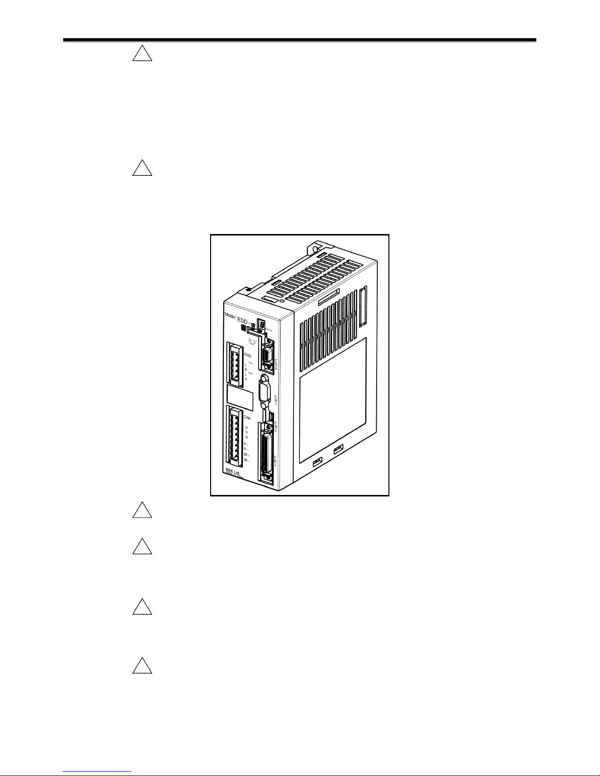
Figure 1-1: Outline of Driver Unit Model EDD
!
Warning : Do not test the insulation of the Driver Unit.
•The high voltage used in the test may destroy the internal circuits of Driver Unit.
!
Caution : In most cases, the Direct Drive Motor System cannot exhibit its full
performance unless the shipping set of the parameters is altered for
actual applications.
•Refer to “5. Tuning” and be sure to set the servo parameters to actual use conditions.
!
Caution : Allowable moment load and axial load depend on Motor size. Please
confirm that actual load conditions are in the limits of the Motor.
•Refer to “2.5. Motor Specifications” for the allowable moment load, axial load and
radial load.
!
Caution : An excessive eccentric load or an excessive load may cause the
permanent deformation of the rotor or premature failure of the bearing
inside the Motor. When handling the Motor, please pay special attention
not to drop it and not to give a shock to it. Protect the Motor from a
collision with an obstacle.

1. Introduction
—1-4 —
•Excessive load to the Motor may damage the bearing of Motor and may
mechanically lock the Motor.
•The flatness of the Motor mounting surface shall be 0.02 mm or less.
!
Caution : For an oscillating operation less than 45 [°], turn the Motor 90 [°] or more
at least once a day.
!
Caution : Do not give a direct impact to the Motor with a hammer or the like. A
direct impact to the outside of the Motor or the load fixed to the Motor
may deteriorate accuracy of the built-in position sensor.
!
Caution : When attaching a rotary machine component to the Motor such as a
bearing or a ball screw, be sure to align both centers within 0.01 mm.
Excessive eccentric load or excessive load to the Motor may cause the
premature failure of Motor’s bearing.
!
Danger : As the Motor may become hot depending on your use conditions, handle
it in a sufficiantly cold state, and be careful of burns, etc.
!
Danger : The Motor has a rotational part and a stationary part. Be careful not to be
caught in the rotational part, including the parts that you install.
!
Warning : Be sure not to activate the dynamic brake in the following conditions.
Otherwise the dynamic brake circuit may break and the Motor will enter in
a “free run”state, leading to possible injuries.
•Do not activate the dynamic brake in normal operations. Stop the Motor by a control
command, not by the dynamic brake. The dynamic brake is an auxiliary function to
stop the Motor immediately in an emergency. In the middle of operation, an alarm, a
warning or the “Emergency stop”input activates the dynamic brake.
Warnings that initiate “Servo-off” state are “A3” (Software thermal), “C0” (Position
command/Feedback error), “F5” (Program error), and “F8” (Automatic tuning
error).
•The load moment of inertia to a Motor must be within the range of the
recommended load moment of inertia described in "2.5 Motor Specifications." In
case of an indexing operation, a position command shall be 360 degrees or less,
while the maximum speed for continual rotation must be 0.5 [s-1] or less.
(However, there may be a possibility to exceed the above limits in some cases.
Please consult NSK when you require a close investigation on the limits.)
•For the PN4180 Motor, be sure to stop the Motor for 20 minutes or longer when you
stop it by the dynamic brake.
!
Caution : When the Motor is continually accelerating a high inertial load with high
acceleration, the system constantly outputs a high torque exceeding the
rated torque, and thus likely to activate the warning “A3” (Software
thermal). In such a case take a remedy to decrease the load moment of
inertia or to lower the speed.
Table of contents
Other NSK Media Converter manuals


Popular Media Converter manuals by other brands


H&B
H&B TX-100 Installation and instruction manual

Bolin Technology
Bolin Technology D Series user manual

IFM Electronic
IFM Electronic Efector 400 RN30 Series Device manual

GRASS VALLEY
GRASS VALLEY KUDOSPRO ULC2000 user manual

Linear Technology
Linear Technology DC1523A Demo Manual

Lika
Lika ROTAPULS I28 Series quick start guide

Weidmuller
Weidmuller IE-MC-VL Series Hardware installation guide

Optical Systems Design
Optical Systems Design OSD2139 Series Operator's manual

Tema Telecomunicazioni
Tema Telecomunicazioni AD615/S product manual

KTI Networks
KTI Networks KGC-352 Series installation guide

Gira
Gira 0588 Series operating instructions

Lika
Lika SFA-5000-FD user guide