Evoqua Wallace&Tiernan 50-200 Series User manual

Series 50-200 Evaporator
For Chlorine
BOOK NO. WT.050.200.001.UA.IM.0814
W3T198237

SERIES 50-200
EVAPORATOR
FOR CHLORINE
W3T198237

EVOQUA W3T98237WT.050.200.001.UA.IM.0814
50-200 EVAPORATOR FOR CHLORINE
ORDERING INFORMATION
WARRANTY
SELLER MAKES NO OTHER WARRANTY OF
ANY KIND, AND THE FOREGOING WARRANTY IS IN LIEU OF ALL OTHER WARRANTIES, EXPRESS OR IMPLIED,
INCLUDING ANY WARRANTY OF MERCHANTABILITY OR OF FITNESS OF THE MATERIAL OR EQUIPMENT FOR
ANY PARTICULAR PURPOSE EVEN IF THAT PURPOSE IS KNOWN TO SELLER.
LIMITATION OF BUYER’S REMEDIES. EXCLUSIVE REMEDY

EVOQUA W3T98237
50-200 EVAPORATOR FOR CHLORINE
WT.050.200.001.UA.IM.0814
The Evoqua Water Technologies Series 50-200 Evaporator for Chlorine de-
scribed in this instrucon book changes the state of chlorine from liquid to
gas to supply other gaseous ow control apparatus.
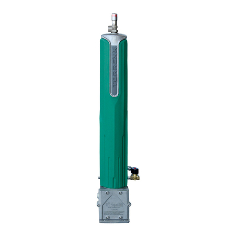
The Series 50-200 Evaporator comprises a steel cylinder immersed in a hot
water bath, an external heat exchanger, and associated control devices.
This instrucon book covers three versions of the evaporator: (1) standard
version W3T97879, (2) lethal cered version W3T97880, and (3) the MLS
version W3T99684 for our customers located in the People's Republic of China.
Both versions have idencal subassembly and component parts except for the
pressure cylinder. The cylinder in the “standard” version is fabricated to meet
all requirements of Secon VIII of the ASME Code for Unred Pressure Vessels.
The “standard” evaporator is therefore suitable for chlorine, sulfur dioxide,
or ammonia service (as labeled) in all applicaons. If, however, the customer
requires either a “lethal cered” cylinder or a greater wall thickness for extra
corrosion allowance, the “lethal rated” version is provided.
!

EVOQUA W3T98237WT.050.200.001.UA.IM.0814
50-200 EVAPORATOR FOR CHLORINE
Very Important Safety Precauons (Chlorine) ............ 1.010-40,-41
Very Important Safety Precauons ............................. SP-1,-2,-3
Regional Oces .......................................................... 1.010-1
Technical Data ............................................................. Secon 1
Installaon .................................................................. Secon 2
Operaon ................................................................... Secon 3
Service ........................................................................ Secon 4
Illustraons ................................................................. Secon 5
Spare Parts List ........................................................... Secon 6
Literature/Manuals ..................................................... Secon 7
Chlorine Handling Manual ....................................... WT.025.000.001.UA.IM

EVOQUA W3T98237
50-200 EVAPORATOR FOR CHLORINE
WT.050.200.001.UA.IM.0814
This and the following page tled “Very Important Safety Precauons” provide, in brief, informaon of urgent
importance relave to safety in the installaon, operaon, and maintenance of this equipment.
TO AVOID POSSIBLE SEVERE PERSONAL INJURY OR EQUIPMENT DAMAGE, OBSERVE THE FOLLOWING:
THIS EQUIPMENT SHOULD BE INSTALLED, OPERATED, AND SERVICE ONLY BY TRAINED, QUALIFIED PERSON-
NEL WHO ARE THOROUGHLY FAMILIAR WITH THE ENTIRE CONTENTS OF THIS INSTRUCTION BOOK AND THE
CHLORINE GAS HANDLING MANUAL.
CHLORINE GAS IS A RESPIRATORY IRRITANT. EXPOSURE TO CHLORINE GAS IN SUFFICIENT CONCENTRATION
PRODUCES IRRITATION OF THE MUCOUS MEMBRANES, THE RESPIRATORY SYSTEM, AND THE SKIN. IN EXTREME
CASES, SUFFOCATION AND DEATH CAN OCCUR.
WHEN CHANGING CHLORINE CYLINDERS, IT IS RECOMMENDED PRACTICE TO HAVE AN APPROVED GAS
MASK AVAILABLE THAT YOU HAVE BEEN TRAINED TO USE AND YOU MUCH BE COMPLETELY FAMILIAR WITH
YOUR LOCAL PLANT OPERATING AND EMERGENCY PROCEDURES AND CHLORINE INSTITUTE RECOMMENDED
EMERGENCY PROCEDURES.
DO NOT TOLERATE ANY CHLORINE LEAKS. CHLORINE LEAKS NEVER GET BETTER. CHLORINE LEAKS ALWAYS
GET PROGRESSIVELY WORSE IF THEY ARE NOT PROMPTLY CORRECTED. IT IS RECOMMENDED PRACTICE TO
HAVE AN APPROVED GAS MASK AVAILABLE WHEN MAKING LEAK CHECKS.
AS SOON AS THERE IS ANY INDICATION OF CHLORINE IN THE AIR, TAKE IMMEDIATE STEPS TO CORRECT THE
CONDITION.
IMPORTANT INFORMATION RELATED TO SAFETY OF CHLORINATION EQUIPMENT INSTALLATION IS PROVIDED
IN THE CHLORINE GAS HANDLING MANUAL. IN THE INTEREST OF SAFE OPERATION, THIS INFORMATION MUST
BE READ, UNDERSTOOD, AND PRACTICED BY EQUIPMENT OPERATORS AND THEIR SUPERVISORS.
AT TIME OF INITIAL INSTALLATION, WHEN CHLORINE SUPPLY LINES HAVE BEEN DISCONNECTED FOR ANY REA-
SON AND ON A ROUTINE DAILY BASIS, THOROUGHLY CHECK ALL JOINTS, CONNECTIONS, AND EQUIPMENT FOR
POSSIBLE CHLORINE LEAKS AND IMMEDIATELY CORRECT ANY THAT MAY BE FOUND.
WHEN ANY CONNECTION IS BROKEN EVEN FOR A SHORT TIME, IMMEDIATELY PLUG THE RESULTANT OPEN-
INGS WITH A RUBBER STOPPER OR EQUIVALENT TO PREVENT THE ENTRANCE OF MOISTURE. MOISTURE
MUST BE EXCLUDED FROM ANY PART OF THE EQUIPMENT THAT IS NORMALLY EXPOSED TO DRY CHLORINE
ONLY. WHILE DRY CHLORINE IS NON-CORROSIVE, MOIST CHLORINE IS EXTREMELY CORROSIVE TO COMMON
METALS, SUCH AS BRASS OR STEEL.

EVOQUA W3T98237WT.050.200.001.UA.IM.0824
50-200 EVAPORATOR FOR CHLORINE
THE TWO MOST COMMON CAUSES OF CHLORINE PIPING LEAKS ARE:
1. RE-USE OF GASKETS. THIS SHOULD NEVER BE DONE. ALWAYS HAVE AN ADEQUATE SUPPLY ON
HAND AND ALWAYS USE NEW GASKETS OF THE CORRECT MATERIAL AND SIZE AS IDENTIFIED ON
THE EQUIPMENT PARTS DRAWING.
2. IMPROPERLY MADE-UP THREADED PIPE JOINTS. SEE CHLORINE GAS HANDLING MANUAL FOR
RECOMMENDED PROCEDURE.
EXCEPT IN CASES OF LEAK DETECTION OR CALIBRATION ADJUSTMENTS, THE CHLORINE GAS SUPPLY MUST
BE SHUT OFF AT THE GAS SUPPLY CONTAINERS AND THE CHLORINE GAS IN THE SYSTEM EXHAUSTED BEFORE
SERVICING THE EQUIPMENT.
USE ONLY EVOQUA WATER TECHNOLOGIES LISTED PARTS, EXCEPT FOR COMMERCIALLY AVAILABLE PARTS AS
IDENTIFIED ON THE PARTS LIST. THE USE OF UNLISTED PARTS CAN RESULT IN EQUIPMENT MALFUNCTIONS
HAVE HAZARDOUS CONSEQUENCES.
DO NOT DISCARD THIS INSTRUCTION BOOK UPON COMPLETION OF INSTALLATION. INFORMATION PROVIDED
IS ESSENTIAL TO PROPER AND SAFE OPERATION AND MAINTENANCE.
ADDITIONAL OR REPLACEMENT COPIES OF THIS INSTRUCTION BOOK ARE AVAILABLE FROM:
Evoqua Water Technologies
725 Wooten Road
Colorado Springs, CO 80915
Phone: (800) 524-6324
Minor part number changes may be incorporated into Evoqua Water Technologies products from me to me
that are not immediately reected in the instrucon book. If such a change apparently has been made in your
equipment and does not appear to be reected in your instrucon book, contact your local Evoqua Water
Technologies sales oce for informaon.
Please include the equipment serial number in all correspondence. It is essenal for eecve communicaon
and proper equipment idencaon.

EVOQUA W3T98237
50-200 EVAPORATOR FOR CHLORINE
WT.050.200.001.UA.IM.0814
This and the following page tled “Very Important Safety Precauons” provide, in brief, informaon of urgent
importance relave to safety in the installaon, operaon, and maintenance of this equipment.
THIS EQUIPMENT IS SUITABLE FOR USE WITH CHLORINE ONLY. DO NOT USE WITH OTHER GASES. SUCH USE
CAN RESULT IN MALFUNCTION OR FAILURE OF VARIOUS COMPONENTS, CAUSING POSSIBLE SEVERE PER-
SONAL INJURY.
TO AVOID SEVERE PERSONAL INJURY AS A RESULT OF A CHLORINE LEAK(S), ENSURE THAT THE CHLORINATOR
IS READY FOR OPERATION BEFORE CHLORINE IS INTRODUCED INTO THE EVAPORATOR AND ITS CONNECTING
PIPELINES. OPERATION OF THE CHLORINATOR MAY BE NECESSARY TO DISPOSE OF CHLORINE TO PERMIT THE
REPAIR OF LEAKS. IF THE EVAPORATOR IS USED WITHOUT A CHLORINATOR, PROVIDE AN ALTERNATE MEANS
OF DISPOSAL.
IF THE SUPPLY CONTAINER DOES NOT HAVE ADEQUATE RESERVE CAPACITY TO ACCEPT THE MAXIMUM CON-
TENTS THAT ARE BEING FORCED FROM THE EVAPORATOR CYLINDER, DO NOT STOP CHLORINATION. INSTEAD,
IN ORDER TO PREVENT OVER-FILLING AND DEVELOPING EXTREME PRESSURES WITHIN THE SUPPLY CONTAINER,
CLOSE THE SUPPLY VALVE AND USE THE CHLORINATOR OR GAS DISPOSAL SYSTEM TO COMPLETELY EVACUATE
THE EVAPORATOR AND ITS CONNECTING PIPELINES.
TO AVOID SEVERE PERSONAL INJURY OR CYLINDER RUPTURE, DO NOT INSTALL A VALVE OF ANY TYPE
BETWEEN THE EVAPORATOR DISCHARGE AND THE GAS PRESSURE RELIEF SYSTEM. RUN THE OUTFLOW
FROM THE RELIEF VALVE TO ATMOSPHERE. TERMINATE THE RELIEF LINE IN AN AREA WHERE GAS FUMES
CANNOT CAUSE DAMAGE OR INJURY TO PERSONNEL. DO NOT TERMINATE THE RELIEF LINE AT A LOCA-
TION ROUTINELY USED BY PERSONNEL, SUCH AS WORK AREAS OR PATHWAYS, NOR NEAR WINDOWS OR
VENTILATION SYSTEM INTAKES. IF AN AREA MEETING THESE REQUIREMENTS IS NOT AVAILABLE, REFER TO
THE CHLORINE INSTITUTE FOR ALTERNATE METHODS OF DISPOSAL.
TO AVOID AN OVERPRESSURE CONDITION CAPABLE OF RUPTURING THE PIPING SYSTEM AND RESULTING
IN A DISCHARGE OF GAS FROM THE GAS PRESSURE RELIEF SYSTEM, DO NOT CLOSE ANY VALVE OR VALVES
BETWEEN THE EVAPORATOR AND THE CHLORINE SUPPLY WITHOUT FOLLOWING THE EVACUATION PROCE-
DURE DESCRIBED IN THIS INSTRUCTION BOOK. LIQUID CHLORINE HAS A HIGH COEFFICIENT OF THERMAL
EXPANSION. DO NOT CLOSE VALVES IN SUCH A WAY THAT LIQUID CHLORINE MAY BE TRAPPED, SINCE DAN-
GEROUS PRESSURES CAPABLE OF RUPTURING THE PIPING SYSTEM MAY BUILD UP WITH A SMALL INCREASE
IN TEMPERATURE.
DO NOT REMOVE THE PRESSURE RELIEF SYSTEM WHILE THE EVAPORATOR IS PRESSURIZED.
TO AVOID A MAJOR RELEASE OF CHLORINE, DO NOT OPEN THE LIQUID LINE PRESSURE RELIEF SYSTEM WHILE
THE EVAPORATOR IS PRESSURIZED.
THE GAS LINE TO THE REGULATING VALVE MUST BE SHORT WITH A SLIGHT DOWN-GRADE TOWARD THE
EVAPORATOR, ALLOWING ANY RELIQUEFIED CHLORINE TO DRAIN BACK TO THE EVAPORATOR. THIS WILL
PREVENT ANY RELIQUEFIED CHLORINE FROM REACHING AND DAMAGING EQUIPMENT DOWNSTREAM OF
THE REGULATING VALVE.

EVOQUA W3T98237WT.050.200.001.UA.IM.0814
50-200 EVAPORATOR FOR CHLORINE
TO AVOID RUPTURE OF THE SUPPLY CONTAINER, CAUSING POSSIBLE SEVERE PERSONAL INJURY, CLOSE THE
SUPPLY VALVE AND USE THE CHLORINATOR OR GAS DISPOSAL SYSTEM TO COMPLETELY EVACUATE THE EVAPO-
RATOR CYLINDER AND ITS CONNECTING PIPELINES.
ALL TWO-BOLT AMMONIA AND RUPTURE DISC UNIONS ARE ONLY LIGHTLY TIGHTENED FOR SHIPPING. TO AVOID
SEVERE PERSONAL INJURY FROM A CHLORINE LEAK, FIRMLY TIGHTEN ALL UNIONS AFTER PIPING IS INSTALLED.
TO AVOID THE RUPTURE OF THE EVAPORATOR PRESSURE CYLINDER OR ITS CONNECTING PIPELINES, CAUSING
POSSIBLE SEVERE PERSONAL INJURY AND EQUIPMENT DAMAGE, DO NOT ATTEMPT TO DISASSEMBLE OR REPAIR
THE RELIEF VALVE. IF IT MALFUNCTIONS, REPLACE IT.
SECURELY SUPPORT THE EXPANSION TANK (e.g., WITH A BRACKET) TO AVOID DAMAGE THAT COULD RESULT
IN A MAJOR RELEASE OF LIQUID.
USE ONLY WATER TO FILL THE HOT WATER TANK AND HEAT EXCHANGER. DO NOT USE ANY SUBSTITUTE
FLUID. THE BOILING TEMPERATURE OF WATER PROVIDES A LIMIT ON AN ACCIDENTAL OVER-TEMPERATURE
CONDITION, THEREBY LIMITING THE GAS PRESSURE INSIDE THE EVAPORATOR CYLINDER.
THE TOP OF THE TANK WILL BE HOT (180°F). TO AVOID SEVERE PERSONAL INJURY DUE TO HOT SURFACES, DO
NOT REMOVE OR REINSTALL CAPLUG WITH BARE HANDS; USE A GLOVE OR OTHER INSULATING MATERIAL.
WHEN DRAINING HOT WATER OUT OF HEAT EXCHANGER, ALLOW WATER TO COOL BEFORE REMOVING PLUG.
TO AVOID SEVERE PERSONAL INJURY FROM BURNS DUE TO HOT WATER IN SIGHTGLASS TUBE, TURN POWER
OFF AND DRAIN THE TANK ENOUGH SO THAT NO WATER IS VISIBLE IN THE SIGHTGLASS. ALLOW THE SIGHT-
GLASS TO COOL BEFORE HANDLING.
WHEN HANDLING HAZARDOUS MATERIAL, IT IS THE RESPONSIBILITY OF THE EQUIPMENT USER TO OBTAIN AND
OBSERVE ALL SAFETY PRECAUTIONS RECOMMENDED BY THE MATERIAL MANUFACTURER/SUPPLIER.
BOLT THE EVAPORATOR SECURELY TO THE CONCRETE PAD.
LIFT THE EVAPORATOR BY A CRANE HAVING NO LESS THAN A ONE-TON CAPACITY RATING.
TO AVOID SEVERE PERSONAL INJURY FROM ACCIDENTAL EXPOSURE TO HIGH VOLTAGE, THE EVAPORATOR
MUST BE SUITABLY GROUNDED TO EARTH BEFORE START-UP. USE THE GROUNDING CONNECTOR PROVIDED.
LINE VOLTAGE IS PRESENT INSIDE THE CONTROL BOX EVEN WHEN THE PANEL POWER SWITCH IS IN THE OFF
POSITION. TO AVOID POSSIBLE SEVERE PERSONAL INJURY DUE TO ELECTRICAL SHOCK, DISCONNECT THE EX-
TERNAL POWER SUPPLY BEFORE SERVICING.

EVOQUA W3T98237
50-200 EVAPORATOR FOR CHLORINE
WT.050.200.001.UA.IM.0814
TO AVOID POSSIBLE SEVERE PERSONAL INJURY FROM ELECTRICAL SHOCK, BE CAREFUL NOT TO TOUCH THE
METAL SCREWS ON THE TERMINALS OF THE PRESSURE SWITCH. THESE TERMINALS ARE CONNECTED TO 115
VOLTS.
TO AVOID POSSIBLE SEVERE PERSONAL INJURY DUE TO EQUIPMENT MALFUNCTION, SEMI-ANNUALLY MAKE A
COMPLETE ELECTRICAL CHECK OF THE OPERATION OF THE TEMPERATURE, WATER LEVEL AND PRESSURE RELIEF
ALARM SWITCHES. IF THE APPROPRIATE RESPONSE IS NOT OBSERVED, REPLACE THE FAULTY CONTROL UNIT.
THE TWO MOST COMMON CAUSES OF CHLORINE PIPING LEAKS ARE:
1. RE-USE OF GASKETS. THIS SHOULD NEVER BE DONE. ALWAYS HAVE AN ADEQUATE SUPPLY ON HAND
AND ALWAYS USE NEW GASKETS OF THE CORRECT MATERIAL AND SIZE AS IDENTIFIED ON THE EQUIP-
MENT PARTS DRAWING.
2. IMPROPERLY MADE-UP THREADED PIPE JOINTS. SEE CHLORINE HANDLING MANUAL FOR RECOM-
MENDED PROCEDURE.
USE ONLY EVOQUA WATER TECHNOLOGIES LISTED PARTS, EXCEPT FOR THOSE COMMERCIALLY AVAILABLE
PARTS IDENTIFIED BY COMPLETE DESCRIPTION ON THE PARTS LIST. THE USE OF UNLISTED PARTS CAN RESULT
IN EQUIPMENT MALFUNCTIONS CAUSING POSSIBLE SEVERE PERSONAL INJURY.
DO NOT DISCARD THIS INSTRUCTION BOOK UPON COMPLETION OF INSTALLATION.
INFORMATION PROVIDED IS ESSENTIAL TO PROPER AND SAFE OPERATION AND MAINTENANCE.
ADDITIONAL OR REPLACEMENT COPIES OF THIS INSTRUCTION BOOK ARE AVAILABLE FROM:
Evoqua Water Technologies
725 Wooten Road
Colorado Springs, CO 80915
Phone: (800) 524-6324
Minor part number changes may be incorporated into Evoqua Water Technologies products from me to me
that are not immediately reected in the instrucon book. If such a change apparently has been made in your
equipment and does not appear to be reected in your instrucon book, contact your local Evoqua Water
Technologies sales oce for informaon.
Please include the equipment serial number in all correspondence. It is essenal for eecve communicaon
and proper equipment idencaon.

EVOQUA W3T98237WT.050.200.001.UA.IM.0814
50-200 EVAPORATOR FOR CHLORINE
Direct any quesons concerning this equipment that are not answered in the instrucon book to the Reseller
from whom the equipment was purchased. If the equipment was purchased directly from Evoqua Water Tech-
nologies, Colorado Springs, CO contact the oce indicated below.
725 Wooten Road
Colorado Springs, CO 80915
TEL: (800) 524-6324
If the equipment was purchased directly from Evoqua Water Technologies, Canada, contact the nearest oce
indicated below.
Evoqua Water Technologies Ltd. Evoqua Technologies des Eaux Itee
2045 Drew Road 505 Levy Street
Mississauga, Ontario St. Laurent, Quebec
L5S 1S4 H4R 2N9
(905) 944-2800 (450) 582-4266

50-200 EVAPORATOR FOR CHLORINE
WT.050.200.001.UA.IM.0814 EVOQUA W3T98237
PARA. NO.
General ............................................................................. 1.1
Applicaon........................................................................ 1.2
Technical Data ................................................................... 1.3

WT.050.200.001.UA.IM.0814
50-200 EVAPORATOR FOR CHLORINE
EVOQUA W3T98237
The Series 50-200 Evaporator is available for either Indoor or Outdoor Service
(oponal), and in the following chlorine evaporang capacies:
• 6,000 lb/24 hr. maximum capacity with 12 kW heaters.
• 8,000 lb/24 hr. maximum capacity with 15 kW heaters.
• 10,000 lb/24 hr. maximum capacity with 18 kW heaters.
Part numbers for these arrangements are provided in Secon 5. See Dwg.
50.200.060.010.
!

50-200 EVAPORATOR FOR CHLORINE
WT.050.200.001.UA.IM.0814 EVOQUA W3T98237
6,000, 8,000 or 10,000 lb/24 hr. depend-
ing on heater size.
Electrically powered hot water heat
exchanger.
3-phase power at nominal voltage level
determined by customer during order.
Available nominal voltage requirements
are: 208V, 220V, 240V, 380V, 440V, 480V,
and 550V.
10 psi minimum city quality water
30-140 psi
560 psi
560 psi
1100 lb. (approximately)

WT.050.200.001.UA.IM.0814
50-200 EVAPORATOR FOR CHLORINE
EVOQUA W3T98237

50-200 EVAPORATOR FOR CHLORINE
WT.050.200.001.UA.IM.0814 EVOQUA W3T98237
PARA./DWG. NO.
General ......................................................................... 2.1
Unpacking and Base Mounng ..................................... 2.2
Piping ............................................................................ 2.3
Chlorine Gas and Liquid Piping .................................. 2.3.1
Water Piping .............................................................. 2.3.2
Evaporator Gas Pressure Relief System ........................ 2.4
Gas Pressure Relief Valve Discharge Piping ............... 2.4.1
Liquid Line Pressure Relief System ............................... 2.5
Wiring ........................................................................... 2.6
Controls ..................................................................... 2.6.1
Heat Exchanger ......................................................... 2.6.2
Hot Water Circulang Pump ...................................... 2.6.3
Evaporator Gas and Liquid Line Pressure
Relief Systems ........................................................ 2.6.4
Illustraons
Dimensions ................................................................ 50.200.100.010A&B
Typical Installaon ..................................................... 50.200.110.010A&B
Installaon - Evaporator Liing Method ................... 50.200.110.030
Installaon Wiring
Evaporator .............................................................. 50.200.130.010
Pressure Relief System-Alarm Switch ..................... 50.200.130.020

WT.050.200.001.UA.IM.0814
50-200 EVAPORATOR FOR CHLORINE
EVOQUA W3T98237
The Series 50-200 Evaporator is shipped completely assembled and ready for
installaon. For the locaon of the various evaporator components, see Dwg.
50.200.110.010.
a. Unfasten and remove shipping crate.
b. If a back cover (outdoor opon) was provided, remove it. Loosen and re-
move the bolts located at the top of the evaporator where the enclosure
sides are fastened together.
c. Loosen the black, quarter-turn screws in the side panels of the enclosure.
d. Remove the side panels. Do not replace them unl the evaporator is ready
for operaon.
e. Remove top cover and pipe trim.
f. Aach two liing hooks, each with no less than 1/2-ton capacity rang, to
the liing brackets that extend out a few inches from the gray insulaon
ring.
g. Chain the liing hooks together to a hoist or crane.
!
!
!

50-200 EVAPORATOR FOR CHLORINE
WT.050.200.001.UA.IM.0814 EVOQUA W3T98237
h. Unbolt the evaporator from the wooden base. Li and lower the evapora-
tor onto a concrete mounng pad prepared according to the mounng
details in Dwg. 50.200.100.010. Bolt the evaporator to the pad.
f. Replace top cover and pipe trim.
An ammonia-type union is furnished to accommodate the one-inch chlorine
gas outlet (discharge) pipe. The chlorine gas outlet pipe and union extends
upward from the gray insulaon ring at the top of the evaporator. The gas
pressure relief system and a vacuum regulator-check unit (or gas pressure
reducing valve) must be installed in this line. Refer to Dwg. 50.200.110.010 for
proper installaon. The vacuum regulator-check unit is electrically operated.
The gas pressure reducing valve can be pilot-operated by air or water or can
be electrically operated. Separate instrucons are furnished with either valve.
There are two points at which chlorine liquid can be brought into the evapora-
tor. The top connecon may be used as a convenience from a piping standpoint
when there is only a single evaporator being used. The boom connecon is
required when manifolding several evaporators for high capacity. For single
evaporators, the boom connecon provides an alternate inlet connecon.
The boom connecon is also used as a drain when cleaning the evaporator
in place. Ammonia unions are furnished at both liquid inlet points.
!
!
!

WT.050.200.001.UA.IM.0814
50-200 EVAPORATOR FOR CHLORINE
EVOQUA W3T98237
In the unlikely occurrence of a leak in the evaporator pressure cylinder, chlo-
rine may be present in the water drain-overow and vapor vent outlet lines.
a. Make a 1-1/4-inch connecon to the combinaon water bath drain-over-
ow line, and connect it to the appropriate plant piping.
b. Make a 1-1/4-inch connecon to the vapor vent outlet and connect it to
the appropriate plant piping.
c. Connect a 1/2-inch supply (10 psi min., 135 psi max.) to the water supply
for the purpose of water make-up to the hot water tank.
The Gas Pressure Relief System (see Dwg. 50.202.008.011, Secon 5) is provided
as a preassembled unit.
Install the Gas Pressure Relief System in the gas discharge line as shown in
Dwg. 50.200.110.010. The purpose of this system is to prevent rupture of
the pressure cylinder or related piping in case of an extreme over-pressure
condition. A detailed view of this system is provided in Dwg. 50.202.008.011.
!
!
!

50-200 EVAPORATOR FOR CHLORINE
WT.050.200.001.UA.IM.0814 EVOQUA W3T98237
To provide for fricon losses, use the following pipe sizes:
Discharge line less than 50 feet long: use 1-or 1-1/2-inch, schedule 40
carbon steel pipe.
Discharge line 50 to 100 feet long: use 1-1/2-inch, schedule 40
carbon steel pipe.
The ASME Boiler and Pressure Vessel Code, Secon VIII Division 1 UA-356, ap-
pendix M, provides guidance for relief system discharge piping. The following
is an excerpt from that code:
UA-356 Discharge Lines From Safety Devices.
(a) Where it is feasible, the use of a short discharge pipe or vercal riser, con-
nected through long-radius elbows from each individual device, blowing
directly to the atmosphere, is recommended. Such discharge pipes shall
be at least of the same size as the valve outlet….
(b) When discharge lines are long … the eect of the back pressure that may
be developed therein … must be considered ….
(c) All discharge lines shall be run as direct as is praccable to the point of
nal release for disposal. For the longer lines, due consideraon shall
be given to the advantage of long-radius elbow, avoidance of close-up
ngs, and the minimizing of excessive line strains by expansion joints
and well-known means of support to minimize line-sway and vibraon
under operang condions.
If liquid is trapped in the supply pipe between two pipes, liquid expansion can
result in pipe rupture. To avoid this, a means of pressure relief is furnished.
(See the Chlorine Handling Manual.)
Table of contents
