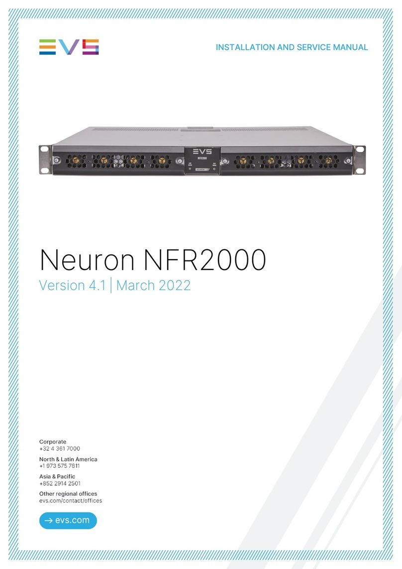
EVS Synapse SFR04 Instruction sheet

INSTALLATION &
CONFIGURATION
MANUAL
SFR04/08/18
4, 8 AND 18 SLOT FRAMES

INSTALLATION AND
CONFIGURATION MANUAL
SFR04/08/18
2
Copyright
EVS Broadcast Equipment S.A. – Copyright © 2001 – 2021. All rights reserved.
Disclaimer
The information in this manual is furnished for informational use only and subject to change
without notice. While every effort has been made to ensure that the information contained in
this user manual is accurate, up-to-date and reliable, EVS Broadcast Equipment cannot be held
responsible for inaccuracies or errors that may appear in this publication.
Improvement Requests
Your comments will help us improve the quality of the user documentation. Do not hesitate to
send improvement requests, or report any error or inaccuracy on this user manual by e-mail to
Regional Contacts
The address and phone number of the EVS headquarters are usually mentioned in the Help >
About menu in the user interface.
You will find the full list of addresses and phone numbers of local offices either at the end of this
user manual (for manuals on hardware products) or on the EVS website on the following page:
http://www.evs.com/contacts.
User Manuals on EVS Website
The latest version of Media Infrastructure manuals are available at: https://mi-sftp.evs.com/
The user manuals for other EVS products can be found at the EVS download center, on the
following webpage: https://www.evs.com/en/download-area.

EVS Broadcast Equipment SA
3
WARNING: TO REDUCE THE RISK OF FIRE OR
ELECTRICAL SHOCK, DO NOT EXPOSE THIS
APPLIANCE TO RAIN OR MOISTURE
● ALWAYS disconnect your entire system from the AC mains before cleaning any component. The product
frame (SFR18 or SFR04) must be terminated with three-conductor AC mains power cord that includes an
earth ground connection. To prevent shock hazard, all three connections must always be used.
● NEVER use flammable or combustible chemicals for cleaning components.
● NEVER operate this product if any cover is removed.
● NEVER wet the inside of this product with any liquid.
● NEVER pour or spill liquids directly onto this unit.
● NEVER block airflow through ventilation slots.
● NEVER bypass any fuse.
● NEVER replace any fuse with a value or type other than those specified.
● NEVER attempt to repair this product. If a problem occurs, contact your local EVS distributor.
● NEVER expose this product to extremely high or low temperatures.
● NEVER operate this product in an explosive atmosphere.
Warranty: EVS warrants their products according to the warranty policy as described in the general terms.
That means that EVS Broadcast Equipment SA can only warrant the products as long as the serial numbers
are not removed.
Copyright © 2001 – 2021 EVS Broadcast Equipment SA
Date created: 11-07-2007
Date last revised: 06-02-2017
EVS, the EVS logo and Synapse are trademarks of EVS Broadcast Equipment SA
This product complies with the requirements of the product family standards for audio, video, audio-visual
entertainment lighting control apparatus for professional use as mentioned below.
EN60950
EN55103-1: 1996
EN55103-2: 1996
Safety
Emission
Immunity

INSTALLATION AND
CONFIGURATION MANUAL
SFR04/08/18
4
UL
Warning
Troubleshooting must be performed by a trained technician. Do
not attempt to service this equipment unless you are qualified to
do so.
Check that the correct fuses have been installed. To reduce the
risk of fire, replace only with fuses of the same type and rating.
This equipment has more than one power supply. To reduce the
risk of electric shock, disconnect both power supply cords before
servicing.
This apparatus must be earthed. Use only certified power cables.
The front of the frame may only be opened by trained service
personnel.
Installation and maintenance of the SFR04, SFR08 and SFR18 is
considered service action.
The service area should be closed the proper way after service
actions to guarantee safe operation. The service areas are marked
with the label shown left.
No user serviceable parts are inside. Refer all service to qualified
personnel.
Warning, hazardous moving parts inside fan tray. Keep fingers
and other body parts away.
The opened front lid may not be used as a shelf to store objects.
Chapters containing service actions are marked with an
exclamation mark.
This equipment is only for use at altitudes not more than 2000m
above sea level or equivalent.
This equipment is only for use in non-tropical conditions or
equivalent.
Exposed portions of the power supply assembly are electrically “hot”. To reduce the risk of electrical
shock, the power cord must be disconnected when the power supply assembly is removed.
The ground terminal of the power plug is connected directly to
the chassis of the unit. For continued protection against electric
shock, a correctly wired and grounded (earthed) three-pin
power outlet must be used. Do not use a ground-lifting adapter
and never cut the ground pin on the three-prong plug.

EVS Broadcast Equipment SA
5
Table of Contents
UL 4
Table of Contents
5
Preface 7
Manual information 7
Purpose 7
Audience 7
Revision history 7
Writing styles 7
Unpacking and shipping 8
Unpacking 8
Shipping 8
Chapter 1: Introduction 9
Introduction to Synapse 9
An Introduction to Synapse 9
Local Control Panel 9
Remote Control Capabilities 9
Product Description 10
General description 10
Main features 10
Complementary cards 10
ADD-ON Daisy Chain Bus 10
Chapter 2: Installation 12
Unpacking the frames 12
Preparing the product for installation 12
Unpacking 12
Inserting into racks 12
Card installation 13
General module layout 13
Inserting cards in an SFR18 frame 13
Opening the front lid 13
Inserting cards in an SFR04 or SFR08 frame 15
I/O-panel installation 16
Connector panel color coding 16
Applying the connector sticker 16
Inserting the I/O-panel 16
Inserting a I/O panel 17
Inserting a I/O-panel into an SFR18 frame 17
Inserting a I/O-panel into an SFR04 or SFR08 frame 17
Chapter 3: Maintenance 18
Fan replacement 18
Replacing fans in an SFR18 frame 18
Replacing fans in an SFR04 frame 18
Replacing fans in an SFR08 18
Power supply replacement 19
Replacing a power supply in an SFR18 19
Replacing a power supply in an SFR04 or SFR08 19
Chapter 4: Configuring the Synapse frame 20
A Quick Start 20
Powering-up 20
Changing settings and parameters 20
Front Panel Control 20
Example of changing parameters using front panel control 21

INSTALLATION AND
CONFIGURATION MANUAL
SFR04/08/18
6
EVS Cortex Software 22
Menu Structure Example 22
Chapter 5: Specifications 23
Frames 23
Dimensions 23
Weight 23
Power 23
Cooling 25
Fan noise 25
Rack Controllers 26
Contacting EVS customer support 27

EVS Broadcast Equipment SA
7
Preface
Manual information
Purpose
This manual details the features, installation, service, operation and
specifications of the SFR04, SFR08 and SFR18 frames.
Audience
This manual is written for the engineers, technicians, operators and
other broadcasting employees that are responsible for the proper
installation and/or operation of the SFR04, SFR08
and SFR18
frames.
Revision history
Edition
Date
Revision
A
July 2007
First draft version
B
January 2008
Final version
C
March 2008
Added SFR08
D
May 2010
Updated revision
E
September 2012
ERC-ERS update
F
November 2014
Added SMP75
G
April 2016
Added SMP45
H
February 2017
Added Gen3 specs
Writing styles
To make this document easier to understand, this manual contains
the following text styles:
Style
Description
Bold
Chapter titles, paragraph titles, table
headers.
Italic
Special words that need emphasis
CAPS
Indicates a keystroke on the keyboard,
such as ENTER, CTRL, SHIFT or ALT.
Display
Indicates text which can be seen on the
synapse control display
>
Indicates the direction of navigation
through a menu structure.
Note
Indicates important information that helps
to avoid problems.
Indicates service areas which may only be
performed by trained service personnel.

INSTALLATION AND
CONFIGURATION MANUAL
SFR04/08/18
8
Unpacking and shipping
Unpacking
EVS has carefully inspected this product before shipment to ensure
years of trouble-free service.
Upon reception, please make sure you:
1- Check products for any visible damage that may have
occurred during transit.
2- Confirm that you have received all products listed on the
packing list.
3- Contact your EVS dealer if any product on the packing list
is missing.
4- Contact the carrier if any item is damaged.
5- Remove all packing material from the products before you
install them, in an anti-static environment.
Shipping
Keep at least one set of original EVS packaging in case you need
to return a product for servicing or replacement. If there is no
original packaging available, please use your own packaging as
long as it meets the following criteria:
•Withstand the weight of the product
•Holds the product rigid within the packaging
•Leaves at least 5 cm of space between the product and the
container
•Protects the corners of the product

EVS Broadcast Equipment SA
9
Chapter 1: Introduction
Introduction to Synapse
An Introduction to
Synapse
EVS is a modular system designed for the broadcast industry. High
density, intuitive operation and high-quality
processing are key
features of this system. Synapse offers a full range of converters
and processing modules. Please visit the EVS website at
http://www.evs.com/ to obtain the latest information on our new
products and updates.
Local Control Panel
The local control panel gives access to all adjustable parameters
and provides status information for any of the cards in the Synapse
frame, including the Synapse rack controller. The local control
panel is also used to back-up and restore card settings. Please refer
to the ERC118, ERS118, ERC108, ERS108, RRC18, RRC08,
RRC04, RRS18, RRS08 and RRS04
manuals for a detailed
description of the local control panel, the way to set-
up remote
control over IP and for frame related settings and status
information.
Remote Control
Capabilities
The remote control options are explained in the rack controller
manual. The method of connection to a computer using Ethernet is
described in the ERC, ERS, RRC or RRS manual.
Note
“EVS Cortex” software will increase system
flexibility of one or more Synapse frames
Although you are not required to use Cortex with a Synapse frame,
you are strongly advised to use a remote personal computer or
laptop PC with the EVS Cortex software installed as this increases
the ease of use and understanding of the modules. This program is
downloadable on our website (http://www.evs.com/
) free of
charge.

INSTALLATION AND
CONFIGURATION MANUAL
SFR04/08/18
10
Product Description
General description
The SFR04, SFR08 and SFR18 are frames that can contain 4
(SFR04), 8 (SFR08) and 18 (SFR18) synapse modular cards. The
SFR04 is 1RU, the SFR08 is 2RU and the SFR18 is 4RU high.
Together with the Rack Controller Card (ERC, ERS, RRC or RRS)
and the power supply (optional redundant power supply in the
SFR18 and SFR08) the frames form the base of the Synapse system.
Main features
SFR18 features include the following:
•Robust design
•Control panel in the front of the frame
•Option for a redundant power supply
•Easy, hot swappable fans
•Internal Synapse daisy chain bus
•Separate rack controller slot which doesn’t take up a card slot
SFR08 features include the following:
•Robust design
•Control panel in the front of the frame
•Option for a redundant power supply
•Easy, front removable, hot swappable fans
•Internal Synapse daisy chain bus
•Separate rack controller slot which doesn’t take up a card slot
SFR04 features include the following:
•Robust design
•Control panel in the front of the frame
•Internal Synapse daisy chain bus
•Separate rack controller slot which doesn’t take up a card slot
Complementary cards
Frames must have one of the following Rack Controller Cards
installed to work properly:
•RRC18 (normal rack controller for SFR18)
•ERC118 (enhanced rack controller for SFR18)
•RRC10 (former model rack controller for SFR18)
•RRC08 (normal rack controller for SFR08)
•ERC108 (enhanced rack controller for SFR08)
•RRC04 (normal rack controller for SFR04)
•RRS18 (rack controller with SNMP functionality for SFR18)
•ERS118 (enhanced rack controller with SNMP for SFR18)
•RRS08 (rack controller with SNMP functionality for SFR08)
•ERS108 (enhanced rack controller with SNMP for SFR08)
•RRS04 (rack controller with SNMP functionality for SFR04)
ADD-ON Daisy Chain
Bus
All Synapse frames contain the unique ADD-ON daisy chain bus. It
enables you to embed audio and
even video from one card to the
other from within the frame (instead of external physical wires). The
bus is a central (passive) interface between the power supply, the

EVS Broadcast Equipment SA
11
front panel control and the cards.
The dedicated wires running from slot-to-slot prov
ide the
opportunity to send signals to and from a card placed immediately
on the right-hand side.
Beside the ADD-ON bus there is also an
internal bus which
distributes reference, power and control/monitoring data to all cards.
To visualise this, the following graphic is made which displays the
functionality of the internal Synapse bus.
•The daisy chain ADD-ON
bus is passive, guaranteeing
absolute stability.
•The ADD-ON
principle can be started anywhere in the
frame.
•The ADD-ON card is placed immediately on the right side of
the master card (front view).
•ADD-ON and master cards can work as standalone cards as
well as working together, all user-configurable (via position
in the chain or via card settings.
•Up to sixteen channels of audio can be transported to or from
a master card with a maximum of four ADD-ON cards.
•Allows transport of 1 DVI signal from one card to the other
over the daisy-chain (for instance with multi-view modules).
•Distribution of reference, power and control/monitor data is
done via separate wires on the bus autonomous of the ADD-
ON chain.
,

INSTALLATION AND
CONFIGURATION MANUAL
SFR04/08/18
12
Chapter 2: Installation
Unpacking the frames
Preparing the product
for installation
Before installing the frames, please do take the following step:
•Check the product for any visible damage that may have
occurred during transit.
•Confirm receipt of all products on the packing list.
•Retain the original packaging for possible re-use.
See “Unpacking and shipping” for more information about returning
a product for servicing or replacement.
Note Contact your EVS
dealer if parts are missing or
damaged or when products on the packing list are
missing.
Unpacking
The EVS Synapse frame must be unpacked and installed in an anti-
static environment. Make sure all package material on de outside
and the inside of the frames are removed before putting it into
operation.
Inserting into racks
SFR frames fit in standard 19” racks. Air-cooled racks are preferred.
The frame’s own cooling design works with air outlets to the side of
the units. Installation of the equipment in a rack should be in the way
that the amount of air flow required for safe operation of the
equipment is not compromised.Please make sure there is sufficient
space and airflow on the left and right side of the frames. Also,
please make sure that when you are stacking frames directly on top
of each other, to keep a nominal distance of 2 millimetres between
the frames.
If installed in a closed or multi-unit rack assembly, the operating
ambient temperature of the rack environment may be greater than
room ambient. Therefore, consideration should be given to installing
the equipment in an environment compatible with the specified
maximum ambient temperature.
SFR frames should be mounted firmly in 19” racks by using valid
mounting material at the front. The SFR frame should also have a
solid support at the backside to prevent personal injury, damage to
the frame or improper operation.
Mounting of the equipment in the rack should be such that a
hazardous condition is not achieved due to uneven mechanical
loading.

EVS Broadcast Equipment SA
13
Consideration should be given to the connection of the equipment to
the supply circuit and the effect that overloading of the circuits
might have on over current protection and supply wiring.
Appropriate consideration of equipment nameplate ratings should be
used when addressing this concern.
A reliable earth connection of rack-mounted equipment should be
maintained. Particular attention should be given to supply
connections other than direct connections to the branch circuit (e.g.
use of power strips).
Installing the SFR frame is a service action and may only be
performed by trained service personnel.
After installation of a SFR18 frame the “Front panel screws” should
be tightened with a screwdriver to prevent unauthorized access by
untrained personnel and to avoid unsafe situations.
Card installation
General module
layout
In general, a Synapse card layout looks like as shown in the picture
below. Displayed in the picture are the most important parts of a
synapse card.
Inserting cards in an
SFR18 frame
To insert the card into an SFR18 frame you first open the front lid
and take off the card holder bar which holds all the cards in place.
Insert the card into an empty slot of the frame as shown in the
picture below.
Opening the front lid
The front is secured by “Front panel screws” and may only be
opened by trained service personnel. After performing service, the
“Front panel screws” should be fastened before continuing normal
operation. Touching live parts inside the SFR18 frame can cause an
energy hazard! Installation or changing the configuration of cards
with an open front lid is considered to be a service action. Leaving
the front unguarded open after a service action must be avoided to
prevent unsafe situations.

INSTALLATION AND
CONFIGURATION MANUAL
SFR04/08/18
14
With the SFR18 frame make sure both sides of the card are
following the frame rails, so the card is guided exactly into the
frame’s internal bus connector. Push the card firmly into the internal
bus connector. When the card is installed, place back the card holder
bar.
Note
If you are going to use ADD-ON cards with a
master card in the SFR18 frame, make sure the
master card is placed left, next to the ADD-ON
card(s).

EVS Broadcast Equipment SA
15
Inserting cards in an
SFR04 or SFR08 frame
To insert the card into an SFR04 or SFR08 frame you first
completely pull out the front lid with the handles, so the control
panel unfolds. Insert the card into an empty slot of the frame like
shown in the picture below (showing SFR04, with SFR08 it looks
the same with the only difference that it has 8 slots instead of 4)
With the SFR04 and SFR08 frames make sure both sides of the card
are following the glides, so the card is guided exactly into the
frame’s internal bus connector. Push the card firmly into the internal
bus connector
Note
If you are going to use ADD-ON cards with master
cards in a SFR04 or SFR08 frames, make sure the
card is placed in a slot number one number lower
than the ADD-ON card(s). Slot numbers in an
SFR04, seen from the front side, are as follows:
Card slot 2
Card slot 4
Card slot 1
Card slot 3
In an SFR08 frame the slot numbers are as follows:
Card slot 4
Card slot 8
Card slot 3
Card slot 7
Card slot 2
Card slot 6
Card slot 1
Card slot 5

INSTALLATION AND
CONFIGURATION MANUAL
SFR04/08/18
16
I/O-panel installation
Connector panel color
coding
The Synapse system uses different connector and card-grip sticker
colors to give you a clear view on which card has which function.
These color codes are the following:
(yellow)
(orange)
(red)
(green)
(dark blue)
(purple)
(turquoise)
(light blue)
(dark red)
(dark green)
(violet)
(brown)
= Analog audio distribution
= Analog video distribution
= Audio A/D conversion
= Audio D/A conversion
= Audio for video
= Audio processing
= Digital audio distribution
= Digital video distribution
= Video A/D conversion
= Video D/A conversion
= Video processing
= Synapse Miscellaneous
Applying the
connector sticker
The connector sticker is sometimes delivered separately with the
I/O-panel. It fits exactly over the I/O-panel and gives it the right
color with the correct connector descriptions per connector. Make
sure the sticker will be manually applied onto the I/O-panel like
displayed in the picture below before you install the I/O-panel in the
frame.
Inserting the I/O-
panel
When the connector sticker is properly fitted onto the I/O-panel and
the card is inserted into the frame, you can insert the I/O-panel so it
connects to the card. To do this you first have to screw off the
placeholder back plate (if there is one) which is covering the
backplane slot, parallel to the front slot where you inserted the card
into.

EVS Broadcast Equipment SA
17
Inserting a I/O panel
Installation or changing the configuration of I/O planes is considered
to be a service action and may only be performed by trained service
personnel. Empty positions should be closed with a “back-plane
BPL00 (blind panel)” before normal operation to prevent an energy
hazard!
Inserting a I/O-panel
into an SFR18 frame
Slide the backplane gently into the SFR18 as shown in the picture
below (panel type might differ from picture).
There are rails in the frame which guides the I/O-panel so it will fit
exactly into the I/O-panel connector of the card. Firmly push the I/O-
panel into the card’s connector. When the I/O-panel is in place,
screw it steadfast onto the frame with a screwdriver.
Inserting a I/O-panel
into an SFR04 or
SFR08 frame
To insert a I/O-panel in a SFR04 or SFR08, slide the backplane
gently into the frame as shown in the picture below (panel type
might differ from picture). This works the same with an SFR08, with
the only difference that there are 8 slots for I/O-panels.
There are rails in the frame which guide the I/O-panel so it will fit
exactly into the I/O-panel connector of the card. Firmly push the I/O-
panel into the connector. When the I/O-panel is in place, screw it
steadfast onto the frame with a screwdriver.

INSTALLATION AND
CONFIGURATION MANUAL
SFR04/08/18
18
Chapter 3: Maintenance
Fan replacement
Replacing fans in an
SFR18 frame
The fans of the SFR18 frame are not hot swappable. Disconnect
power before replacement. You can take them out on the top of the
frame. Screw loose the 2 screws as shown on the picture below.
Take out the fan-mount and unplug the cable. Take the new ordered
FAN24 unit and plug the cable on the print board of the new FAN24.
Put in the fan unit and screw back in the 2 screws.
Replacing fans in an
SFR04 frame
The SFR04 does not have fans built in the frame. The cooling is
done by the fan which is part of the SFR04’s single power supply.
The fan is not hot swappable. If this fan needs replacement, please
call our support department. They will be glad to help you further.
Replacing fans in an
SFR08
The SFR08 has a front removable fan-tray vertically between the
card slots. These fans are hot-swappable. You can simply pull out
the fan-tray by hand, without the need for other handlings other then
pulling and the front of the SFR08 until it unfolds. This is shown in
the image below. Take a new fan tray, or replace the fans in the
original tray, and slide back in that tray and press firmly.

EVS Broadcast Equipment SA
19
Power supply replacement
Replacing a power
supply in an SFR18
The SFR18 has an option for a redundant power supply. These
power supplies are hot swappable, meaning that if there are 2 power
supplies inserted in the frame you can simply pull out one of the two
power supplies without the frame switching off.
There is a safety pal (black button) which you have to pull until you
feel a click. The power supply is now unlocked. Simply pull out the
power supply (sometimes this requires a little force) and slide it out
of the frame. Put back in the new power supply and push is firmly
into the power connector in the back of the frame. Push the safety
pal until you feel a click. The power supply’s LED should light up
immediately.
Replacing a power
supply in an SFR04 or
SFR08
The SFR04 has no option to redundant power supplies. This means
when you want to replace a power supply in an SFR04, you are
required to switch the entire frame off! This is not the case with an
SFR08, which does have the option for redundant power supplies.
You can pull out the power supply on the front side of the opened
SFR04 or SFR08 frame after you have unplugged the control
panel’s flat cable. Slide back in a new power supply and press
firmly. Plug back in the front-panel’s flat cable before closing the
front.
Note
If there is only one power supply in the frame, do not pull it out
without checking if there is someone or something still using the
cards in the frame. Pulling out a power supply, while there is no
other power supply, will instantly switch off the entire frame. Either
make sure the frame is not being used or insert a redundant power
supply before pulling one out.
If service has to be performed to the frame, assure the power
supplies should be switched off by disconnecting the power cable to
the frame. In case of redundant power supplies always be assured
both power cables are disconnected.

INSTALLATION AND
CONFIGURATION MANUAL
SFR04/08/18
20
Chapter 4: Configuring the
Synapse frame
A Quick Start
Powering-up
On powering up the Synapse frame, the card set will use basic data
and default initialisation settings
. All LEDs will light during this
process. After initialisation, several LEDs will remain lit – the exact
number and configuration is dependent upon the number of inputs
connected and the status of the inputs.
Changing settings and
parameters
The front panel controls or the EVS Cortex Software can be used to
change settings. An overview of the settings can be found in the
manuals of the individual cards.
The front panel controls are only accessible
by trained service
personnel
Front Panel Control
Front Panel Display and Cursor
Settings are displayed and changed as follows:
Use the cursor ‘arrows’ on the front panel to select the menu and
parameter to be displayed and/or changed.
Press ►
To go forward through the menu structure.
Press ◄
To go back through the menu structure.
Press ▲
To move up within a menu or increase the value of
a parameter.
Press ▼
To move down through a menu or decrease the
value of a parameter.
Note
Whilst editing a setting, pressing ► twice will reset
the value to its default.
[No Alarms]
This manual suits for next models
2
Table of contents
Other EVS Computer Hardware manuals
Popular Computer Hardware manuals by other brands

Antec
Antec Perfomance II SX1000II user manual

EK-Quantum
EK-Quantum Vector Strix RTX 3070 Backplate user guide

Alphacool
Alphacool NexXxoS GPX-N 1080Pro-M07 instruction manual

Balluff
Balluff BIS Series Technical manual

AXIOMTEK
AXIOMTEK eBOX560-880-FL Series Quick installation guide

Intel
Intel Xeon E3-1125C user guide