zapco DSP6-SL User manual


1
Contents
Mission Statement 2
How a Balanced Signal System Works 3
Sonic Purity 4
SymbiLink™ Balanced System 5
Zapco Digital 6
The Zapco Digital Programming Network 8
Addressing Components on the DPN 9
DSP6-SL 10
Zapco Digital –Functions and Control 12
The PC Program 13
The PC Programming Screen 20
The DRC-SL In-Dash Programmer 25
Adjustment Screen 27
Menu Map28
DRC-SL Quick Menu 30
Technical Assistance 31

2
Mission Statement
ZAPCO IS DEDICATED TO THE PURSUIT OF AUDIO FIDELITY.
Our passion, our “Driving Force” is to design and manufacture car audio
products of unsurpassed quality, to provide unparalleled support and service
for these products and to conduct business in a manner that will enhance
the quality of life for all involved. There is absolutely no substitute for
experience; that is a simple fact of life. Another simple fact is that for over 30
years, ZAPCO has been the leader in defining quality standards for the car
audio industry. These years of experience have led to a thorough
understanding of the challenges that are unique to the world of car audio.
ZAPCO’s relentless quest for sonic purity consistently yields imaginative
designs that utilize the most innovative technologies. The resulting products
set the criteria by which all others in the industry are judged. Feel the
passion, hear the quality, know the performance and reliability by making
ZAPCO the “Driving Force” in your car audio system.

3
How a Balanced Signal System Works

4
Sonic Purity
Our dedication to sonic purity requires that the highest quality
internal components are used.
•Resistors
All resistors (other than power resistors) are 1% precision low noise
metal film. This is a key reason why ZAPCO products have the industries’
best low noise specifications, and why you won’t see as much fluctuation in
our test certificates as you will with other brands. Precision resistors also
reduce distortion and improve channel matching.
•Capacitors
Capacitors are similar to batteries. Like a battery, they store energy
and have electrolyte (internal fluid). Also like a battery, a capacitor can have
a very limited life. “Computer grade” capacitors for example, are reliable
only in cool environments with very little current applied to them. Only the
best high current and high temperature capacitors should be used in an
auto-sound application. Although these capacitors typically cost five times
as much as those commonly used in other brands, ZAPCO insists that no
audio degradation will occur over time.
•Transistors
Two types of transistors are used in ZAPCO products, bipolar and
MOSFET. MOSFET transistors are rugged, high current output devices that
are best suited as switches. They are the choice for switching power
supplies. They are however, very non-linear and are not suitable for use as
audio outputs. They cannot be matched and their inherent distortion
requires too much feedback to achieve reasonable distortion levels. Bipolar
output transistors are used exclusively in the audio stage of all Reference
Series amplifiers. The audio performance of a bipolar transistor heavily
outweighs any minor advantages a MOSFET might offer regarding
durability. We solve the durability concerns by simply using more output
devices than the amplifier requires. This gives us a bulletproof amp with the
sound quality we demand of a ZAPCO product.
•Transformers
Most of the transformers used in our products are hand-wound to
ensure maximum quality. This provides a guarantee that current capability,
efficiency, and radiated noise are all kept within our demanding parameters.
Another critical aspect of the transformer is mounting; all transformers are
securely mounted in their respective chassis. Transformers are massive,
and if not securely mounted can cause failure among internal components
due to vibration.

5
•Power Supplies
Regulated or Unregulated? For years amplifier designers have
debated which type of power supply is best. What’s the truth about power
supplies? They each have advantages and disadvantages and there is no,
one, best type. Limiting yourself to one type of power supply limits your
amplifier design flexibility. ZAPCO uses both types of power supplies
depending on the intended use of each amplifier, as well as expected
current demands and operating environment.
SymbiLink™Balanced System
The most natural configuration for an audio system in the
automobile places the signal source in the dash with the amplifiers located
some distance away, usually under the seat or in the trunk of the vehicle.
The reality of this arrangement dictates the necessity to make long runs of
low level signal cable usually from the front to the back of the car. The
electrical environment in an automobile is one that is inherently noisy and
filled with conditions that threaten to degrade signal fidelity at every turn.
Capacitive loading due to the long cable lengths, the potential for ground
loops, alternator charging currents or currents generated by the amplifiers
themselves are all factors that induce noise and distortion into the signal
cables. By no means is this an ideal situation. Thankfully, ZAPCO has found
the solution.
SymbiLink™components convert a standard unbalanced audio
signal into the fully balanced domain usually reserved for expensive
professional audio equipment found in recording studios or at your local
concert venue. After this conversion is made, the audio cabling becomes
virtually immune to electrical interference in the surrounding environment
and is much less susceptible to signal degradation over long cable runs. It is
for this reason that balanced signal cables are common in professional or
industrial applications. ZAPCO has made this technology available for your
car. ZAPCO engineers also discovered that the pulsating D.C. current in the
automobile chassis and amplifier power wiring caused a significant amount
of low frequency distortion. ZAPCO's balanced SymbiLink™technology
completely eliminates this distortion.

6
Zapco Digital
Who has the number one name in state of the art audio equipment?
Zapco!
But, when most people think of Zapco, they picture compact, powerful,
great sounding amplifiers. While this picture is true enough, it misses one
big piece of the Zapco legend.
Signal Processing!
Zapco virtually created the concept of high sound quality processing in
the late 70’s when we created the PEQ. This was a high voltage preamp/EQ
with and audiophile input stage and 9 bands of equalization for each
channel. It brought a whole new level of performance to car sound. In the
90’s the name was changed to SEQ and the unit is still in production today.
In the 80’s we took processing to another new level with the PX. This
was the first audiophile quality preamp EQ with a multi-order crossover. In
addition, all four EQ bands were parametric, so now you could customize
the EQ parameters to you car. The result: By the late 80’s even non-Zapco
dealers had to have a source of PX’s for all their competition cars.
The next leap was in the 90’s, when Zapco introduced the SX, (later to
become the SX-SL). This unit expanded the Parametric EQ to 5 bands,
added dual high pass and three way band pass crossovers, added variable
crossover slopes, bass-to-highs balance, and SymbiLink™ Balanced inputs.
Also in the 80’s / 90’s we added the DA II, EQ30, SP-7, and two
electronic crossovers. So by the end of the 90’s many audio competitors
(especially the ones winning) were running two or more Zapco processors.
OK! Cool as that is, it is still just history!
What is Zapco doing for today’s Car Audio fanatic?
We’re Going Digital! Zapco began using on-board digital processing
and control in 1999 as we developed the famous 9.0XD, Class D amplifier.
Now, in 2005 Zapco again takes a concept to an entirely new level of
performance and functionality.

7
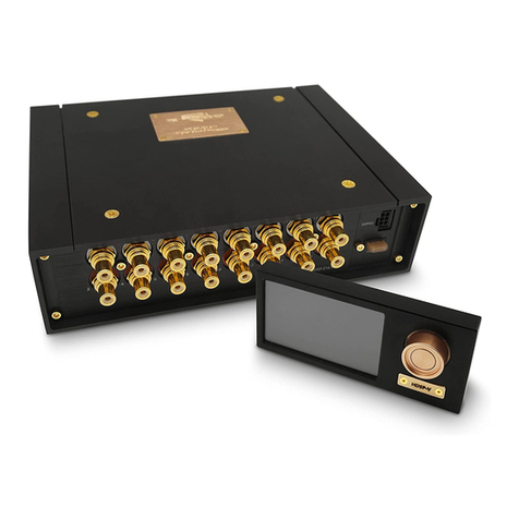
First: We have the DSP6-SL. This is a stand alone Digital Signal
Processor that combines all the functions of an entire array of Zapco
processing into a single compact device. We’ve even added functions never
before available from Zapco processors. The DSP6-SL is programmed and
controlled by a PC through a custom Zapco program designed to be both
full functioned and easy to use.
Second: We’ve developed an entire line of Reference Digital amps,
which have all the DSP6-SL functions on-board. You can just hook up your
Reference Digital amp and play music, or you can add the program to your
PC and have full control of all functions to customize your amp to your
needs.
Third: We have developed the DRC-SL in-dash remote that will allow
you to have immediate 24/7 real time access to your programming right from
your dash.
And, perhaps most significant of all, the Zapco Digital Programming
Network. The network will allow you to control up to 16 amplifiers from a
single DRC-SL or PC. Every Digital series component has a USB port to
allow you to enter the network at any node position and control every
component on the network.
No, Zapco is not the first to put a DSP in a product.
What history will remember though, is that Zapco was the first to do it right.
Welcome to the World of Zapco Digital
In this manual we will take you through the programming and control
functions of the DRC6-SL and the on-board DSP in the Reference Digital
amps as well networking operations of Zapco’s DPN system.

8
The Zapco Digital Programming Network
All Digital Reference amplifiers, and the ZAPCO DSP6-SL, stand-alone
Digital Signal Processor incorporate Zapco’s exclusive Digital Programming
Network™ (DPN). This network allows the user to program all amp functions
using a DRC-SL or a PC. The amps DSP can then be programmed to
control Gain, Volume, Crossover, Q-Bass, Equalization, and even Time
Delay. More importantly, the system allows you to network all amps in your
system so you can control up to 16 amplifiers from a single DRC-SL or, with
a PC from a single window.
While the DRC-SL provides functions never before available, its small
size does limit the graphics of the network and it takes a while to make the
settings through the menu system. To allow higher resolution graphics and
to make the setting go much faster, we have also developed a program that
lets you make all adjustments with a PC. Each Digital Control product has a
USB interface. This allows you to plug a PC into any unit on the network and
control the entire network.*

9
Addressing Components on the DPN
The Digital Programming Network consists of 16 amplifier/DSP nodes
numbered 0 through 15. An extra node (number 16) can be occupied by the
in-dash controller (DRC-SL).
NOTE: Turn all amps off before setting address switches
The binary numbering scheme is shown below with the DIP switch.
Settings for Each Node
When using the DRC-SL, leave all switches in the off position
except the Termination switch. Put Sw6 (Termination) to on. The DRC-SL
will then address to Node 16 (As Below)

10
DSP6-SL
Six Channel Digital Signal Processor
Specifications
THD
Analog < 0.0015
Digital < 0.0008
S/N Ratio
Analog > 99dB
Digital > 100dB
Sensitivity 0.25V to 10V
Control Input Mini USB
Dimensions 8.5”L x 7.4”W x 2.35”H

11
DSP6-SL
Front Panel Connections
1) RCA Inputs-Six channels of input are available through RCA
connectors.
2) DIN Outputs-Three Din Connectors provide six channels of
SymbiLink™ Balanced output.
3) DIP Switch-Six position DIP switch is used to address the unit and
assign a node on the Zapco Digital Programming Network.
4) USB Port-Like all Zapco DC products, the DSP6-SL has a USB port
to interface with a PC for all DSP programming functions.
5) Digital Inputs-Three optical connectors provide optional inputs.
6) Data Connectors-Two RG connectors provide Data in/out for
network cables (and DRC control input)
7) Power Connector-Provides Power, Ground, Turn On, and Aux
+12 volt out

12
Zapco Digital –Functions and Control
The Zapco DSP6-SL is a stand-alone six channel Digital Signal
Processor. It has all the DSP functions of the Reference Digital amps, but,
as a stand-alone piece, it brings the world of Zapco Digital to all amplifiers.
The RCA inputs allow you to use the DSP6-SL with any head unit and
the SymbiLink™ outputs can be connected to any SymbiLink™ amp
directly, or, you can use SymbiLink™ DIN to RCA adaptors to hook the
DSP6 to any RCA input amplifier.
The Zapco Digital functions include Input Sensitivity, Output Gain,
Crossover, Q-Bass, Equalization, and Time Delay. Each Reference Digital
piece also has an Input Commutator that allows any input to be assigned to
any output. The Commutator also allows input pairs to be summed for a 2-
channel mono input to any output channel. All DSP functions may be
applied to each channel independently or they may be applied in stereo
pairs.
Control Methods: Zapco provides two options for control of the Zapco
Digital functions. First; you can load the program included with your digital
product into a PC and program all functions directly from the programming
screen. You will find all functions on a single, easy to use, screen designed
to have the familiar look of Zapco processors.
The other Zapco Digital control option is the DSP-SL. The DRC-SL is an
in-dash piece with a Graphic LCD display and will access all Zapco Digital
functions. Because of the size limitations of the DRC-SL screen, this unit will
take longer to operate than the PC, however unlike the PC, the DRC can be
mounted in-dash and will always be available for needed adjustments.
First we will look at the PC programming method, then we will cover the
use of the DRC-SL in-dash unit.

13
The PC Program
A program disk was included with your Digital Reference Amplifier. The
program will work on any Windows OS from 95 forward. The installation is
fast and straightforward, however, there are minor differences with the
different systems and versions.
On your Digital Reference CD you will find the folder ”ZapcoDPN”. In
most cases you simply open the folder and double click “Setup.exe”.
Setup will install the system on your computer. After the program installs
you will need to install the drivers.
Installation of software
1)Load the Zapco Digital CD and install the program by double clicking
on the set-up icon.
2) Power up all devices connected to the DPN. When all devices are
powered up connect the USB cable between any device and your
computer. Wait a few seconds while the DPN firmware is loaded and
Windows notifies you it has found new hardware.
3) When Windows notifies you it has found new hardware do NOT allow
Windows to install the drivers for you. ALWAYS choose to install the
drivers yourself. Windows 98, 2000 and XP will permit you to search
for a driver. When asked to specify a location browse to (C:\\FTDI USB
DRIVER).
4) Install all drivers. Usually, you will need to install the drivers twice.
5) Run shortcut “ZAPCO DPN” from the start menu or from the desktop.
Details for Windows 98:
After installing the program, plug the mini-USB cable between the PC and
one of the network devices.
Typical: After a few moments the program should say it has found new
hardware and will ask how you want to install the drivers. Click next to
screen A. (Next Page)
At screen A, check “Search for best driver” and click Next to go to screen B.
At screen B, (Next Page) check “Specify a location” and Browse to:
(C:\FTDI USB DRIVER 2) and then click Next.
Drivers will then install. In most cases you will again see the new
hardware screen and you will have to install drivers again. This is because
two different sets of drivers are being installed. In some cases the second
set will install automatically.

14
Alternate: If the “New Hardware” screen does not come up when you plug
in the USB cable, go to Control Panel and open “Install New Hardware”.
Your computer will search for new hardware and offer Screen C. Check
“Yes, the device is on the list” and Highlight Zapco Network Amplifier. Click
Next to go to Screen D.

15
At screen D, click Next to go to Screen A, and proceed as above.

16
Details for Windows 2000, XP, XP Pro:
After installing the program, plug the mini-USB cable between the PC and
one of the network devices.
After a few moments the “Found New Hardware” screen will show.
Caution: The default choice is “Install the software automatically.”
(A-1) Do not use this option!
Mark “Install from a specific location” (A-2) and proceed to Screen B.

17
At screen B, check “Include this location in the search” and browse to
(C:\FTDI USB DRIVER 2). If it is not already in then use the drop down box.
Then click Next to install the drivers. When the drivers start to install you will
see screen C. When this screen shows, click “Continue Anyway”. Drivers
will install and you will go to screen D.

18
From Screen D, click Finish to close the installation, and then open the
shortcut “Zapco DPN” to begin programming your Zapco Digital equipment.
Program Upgrades
The Zapco Digital Programming Network is an evolving entity. As it evolves
we will issue program updates. As noted earlier in the section on
“Addressing” your components their is an upgrade mode for each device.
The upgrade mode is entered by setting address switch #5 to the on
position.
Upgrade Screen

19
To put the network into “Upgrade”:
1) Turn off all network devices and set switch 5 of each to the on
position.
2) Connect the PC to the network with the mini USB cable.
3) Power up the system.
4) Open the Zapco DPN program.
The system will come up in Upgrade Mode as in screen 1 above.
5) Click “Start Upgrade.
6) Screen 2 indicates the first unit has been upgraded.
7) Go to Devices (Screen 3) and chose the next device in the network.
8) Repeat the upgrade process for each device in the network.
9) Shut down the network, turn upgrade switches off and restart
network.
This manual suits for next models
1
Table of contents
Other zapco Computer Hardware manuals