EVVO 20000TLG23P User manual

User manual
PV Grid-Connected Inverter
Product Model: EVVO 20000TLG23P~EVVO 33000TLG23P (2019.04.10)

EVVO 20000TLG23P~EVVO 33000TLG23P
I
II
Notice
The product,service and features that you purchased are bound byEVVO's commercial
contract and terms, The product, service and features (or part of them) described in
this
document may not be in your purchase or usage range. EVVO does not declare or
guarantee
anycontentinthisdocumentexceptthereareother contractualstipulation.
Preface
Outline
Please read the product manual carefully before installation, operation or maintenance. This
Save these instructions!
Thismanualmustbeconsideredasanintegralpartoftheequipment andmustbeavailable
at all times to everyone who interacts with the equipment. The manual must always
accompanytheequipment,evenwhenitistransferredtoanotheruserorfield.
Copyright Declaration
Scope
manual contains important safety instructions and installation instructions that must be
followed during installation and maintenance of the equipment.
Thisproductmanualdescribestheassembly,installation,commissioning,andmaintenanceof
the followinginverters.
EVVO 20000TLG23P, EVVO 25000TLG23P, EVVO 30000TLG23P, EVVO 33000TLG23P
ThecopyrightofthismanualbelongstoEVOLVEENERGY GROUPCO., LIMITEDAny
corporationorindividualshouldnotplagiarize,partiallycopyorfullycopyit(including
software,etc.),andnoreproductionordistributionofitinanyformorbyanymeans.
All rights reserved. EVVO reserves the right of final interpretation. This manualis
subjecttochangeaccordingtouser’s orcustomer’s feedback.
Keep this manual where it will always be accessible.
Target Group
This manual is for qualified person (support person, service person is qualified mentioned in
this manual).
Symbols Used
Thismanualprovidessafetyoperationinformationandusesthesymbolinordertoensure
personalandpropertysecurityandusetheinverterefficientlywhenoperatingtheinverter.
You must understand these emphasized information to avoid the personal injury and
propertyloss.Pleasereadthefollowingsymbolswhichusedinthismanualcarefully.
Danger indicates a hazardous situation which, if not avoided, will result
in death or serious injury.
Danger
Warning indicates a hazardous situation which, if not avoided, could
result in death or serious injury.
Warning
Caution indicates a hazardous situation, if not avoided, could result in
minor or moderate injury.
Caution
Attention indicates there are potential risks. If fail to prevent, may lead
to equipment cannot run normally or property damage.
Attention
Note provides tips that are valuable for the optimal operation of the
product. It can solve your problem and save your time if you read it
carefuly.
Note

EVVO 20000TLG23P~EVVO 33000TLG23P
III
IV
6 Operation interface 43
Table of contents
6.1
Operation and Display Panel 43
6.2
Standard Interface 44
6.3
Main Interface 46
7Trouble shooting and maintenance 57
Preface II
7.1
Trouble shooting 57
7.2
Maintenance 61
1 Basic Safety Information 18 Decommissioning 62
1.1
Safety Instructions 1
1.2
Symbols and Signs 3
2Product characteristics 5
2.1
Product Identification 5
2.2
Function Description 10
2.3
Protection Modules 13
2.4
Efficiency and Derating Curve 13
3Installation 15
8.1
Decommissioning steps 62
8.2
Package 62
8.3
Storage 62
8.4
Disposal 62
9Technical data 63
9.1
Input parameter (DC) 63
9.2
Output parameter (AC) 64
9.3
Efficiency, Safety and Protection 64
9.4
General Data 65
3.1
Installation Process 16
3.2
Checking Before Installation 16
3.3
Tools 18
3.4
Determining the Installation Position 20
3.5
Moving the EVVO 20000TLG23P~EVVO 33000TLG23P 21
3.6
Installing the EVVO 20000TLG23P~EVVO 33000TLG23P 22
10 Quality Assurance 66
4Electrical Connections 24
4.1
Electrical connection 25
4.2
Connecting PGND Cables 25
4.3
Connecting AC Output Power Cables 27
4.4
Connecting Communications Cables 29
4.5
Connecting DC Input Power Cables 36
4.6
Safety check 41
5Commissioning of inverter 42
5.1
Safety Inspection before Commissioning 42
5.2
Start Inverter 42

EVVO 20000TLG23P~EVVO 33000TLG23P
1
2
1
Basic
safety
information
If you have any question or problem when you read the following information,
please contact EVOLVE ENERGY GROUP CO., LIMITED.
Note
Chapter Outline
Please read the safety notice in this manual carefully, if not, it may cause serious
injury or death.
safety instruction
It mainly explains the safety instruction when install and operate the inverter.
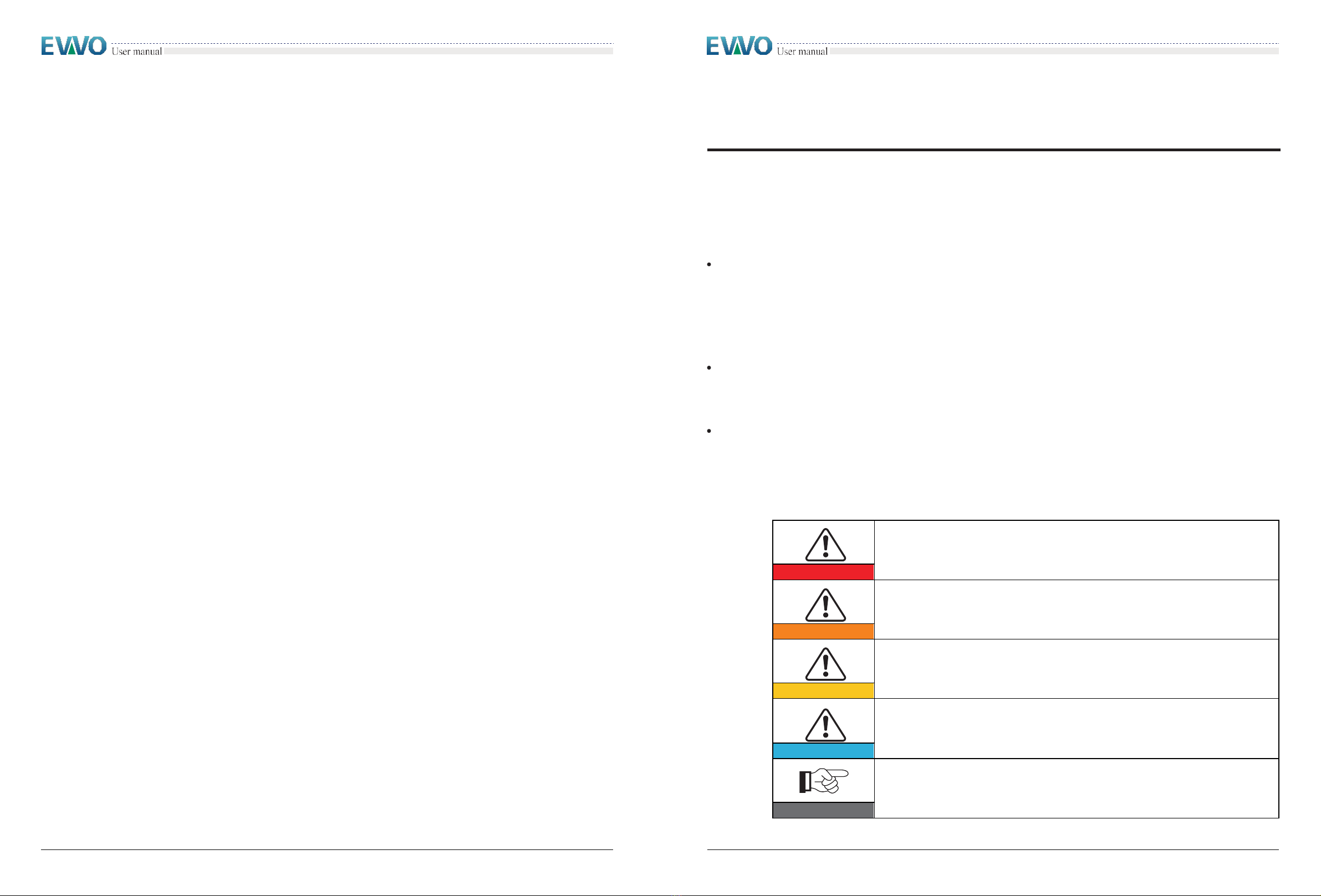
Symbols and signs
It mainly explains the safety symbols on EVVO 20000TLG23P~EVVO 33000TLG23P.
1.1
Safety instructions
The inverter must beinstalled according tothe national andlocal grid standard and law. Read
and understand the instruction of this manual andbe familiar with relevant safety symbols in
the paragraph, then start to install and debug the equipment. According to the national
and state requirements, before connecting the grid, you must get power department
permission, and perform the operation only by qualified electrical engineer. Before
installing and maintaining the equipment, you should cut off the high voltage application
of PV array. You can also open the switch of Solar Array Combiner to cut off the high
voltage. Otherwise, serious injury may becaused.
Body sign and protection
There are warning signs on the body of the inverter,whichhas important safety operation
information, it is forbidden to damage these signs.
Thereisnameplateonsidebodyoftheinverter,whichhasimportantinformationofproduct
parameters,it isforbidden to damagethese signs.
Qualified persons
The customer must make sure the operator has the necessary skill and training to do his/her
job. Staff in charge of using and maintaining the equipment must be skilled, awareand
mature for the described tasks and must have the reliability to correctly interpret what is
described inthemanual.Forsafetyreasononlya qualified electrician,who has received
trainingand
/
orhasdemonstratedskillsandknowledgeinconstructionandinoperationof
thisunit,caninstallthisinverter. EVOLVEENERGY GROUP CO.,LIMITED doesnottakeany
responsibilityforthepropertydestructionandpersonalinjurybecauseofanyincorrectuse.
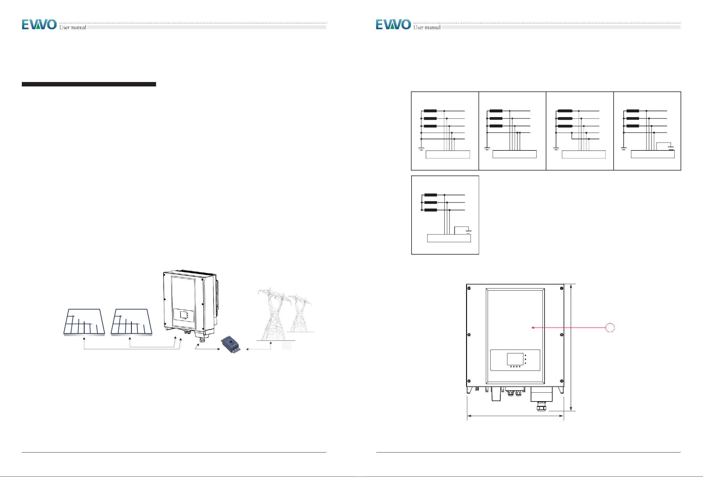
Assembly situation requirements
Please install and start inverter according to the following sections. Put the inverter in
appropriate bearing capacity objects (such as wall and components and so on), to ensure
that inverter vertical placed. Choose suitable place for installing electrical equipment. And
assure
enough fire exit space, convenience for maintenance. Maintain proper
ventilation and ensure thathave theenough air-coolingcycle.
Transport requirements
Ifyoufindpackingproblemsthatmaycausethedamageof theinverter,orfindanyvisible
damage,pleaseimmediatelynoticetheresponsibletransportationcompany.Youcanask
solarequipmentinstallationcontractororEVOLVEENERGYGROUPCO.,LIMITEDforhelpif
necessary. Transport of the equipment, especially by road, must be carried out with by
suitable ways and means for protecting the components (in particular, the electronic
components)fromviolentshocks,humidity, vibration,etc.
Electrical connection
Please comply with all the current electrical regulations about accident prevention in dealing
with the currentinverter.
Before the electrical connection, make sure to use opaque material to cover the
PV modules or to disconnect PV array DC switch. Exposure to the sun, PV array
will produce a dangerous voltage!
Danger
All installation accomplished only by professional electrical engineer!
must be trained;
Completely read the manual operation and understand relevant matters.
Electrical installation and maintenance shall be conducted by qualified
electrician and shall comply with national wiring rules.
Warning
Only get permission by the local power department and complete all electrical
connection by professional electrical engineer then connect inverter into grid!
Attention

EVVO 20000TLG23P~EVVO 33000TLG23P
3
4
Operation
Touching the power grid or the terminal of equipment may lead to die of electric
shock or fire!
Don’t touch the terminal or conductor which connect to the power circuit.
Danger
Some internal components will be very hot when inverter is working. Please wear
protective gloves!
Attention
Maintenance and Repair
Disconnect with the PV components array and electricity grid before any
repair work;
After turning off AC breaker and DC switch for 5 minutes later, the
maintenance or repair of the inverter can be carried out!
Danger
Inverter should work again after removing any faults. If you need any repair
work, please contact with the local authorized service center;
Can’t open the internal components of inverter without authorized. EVOLVE
ENERGY GROUP CO., LIMITED does not take any responsibility for the
losses from that.
Attention
1.2
Symbols and Signs
Signs on the Inverter
There are some symbols which are related to security on the inverter. Please read and
understand the content of the symbols, and then start the installation.
There is residual voltage in the inverter! Before open the equipment, operator
should wait for five minutes after switching off the both AC & DC Side to
ensure the capacitance discharge completely.
Be careful of high voltage.
Be careful of high temperature.
Conformity European with CE.
Point of connection for grounding.
This indicates the allowed temperature range.
IP65
This indicates the degree of protection of the equipment according to IEC
standard 70-1 (EN 60529 June 1997).
Positive pole and negative pole of the input voltage (DC).

EVVO 20000TLG23P~EVVO 33000TLG23P
5
6
2
Product
characteristics
Chapter Outline
Product identification
It introduces the field of use, and how to identify different types of the inverter.
Function description
It introduces how the inverter works and the function modules inside.
Protection modules
It introduces the protection modules in the inverter.
E
f
ficiency
and
de-r
a
t
e
cur
ve
It
in
tr
oduce
e
f
ficiency
cur
ve
and
input/
output
der
a
ting
cur
ve
.
2.1
Product identification
Field of use
The inverter is a multi-string inverter designed to transforma direct electric current (DC)
coming from a photovoltaic generator (PV) into an alternating electric current (AC) Suitable
for being fed into the national grid.
Figure2-1 PV Grid-tied System
Theinvertercanonlybeusedwithphotovoltaicmodulesforon-gridPVpowergeneration.It
cannotbeusedasotherorextrapurposes,Devicemanufactureorsupplierdoesnothave
responsibility to any loss caused by other purpose usage. And customer should take
responsibility to risk and loss of other purpose usage. Customer should follow this manual
for PV on-grid power generation usage. The input of inverter can only be PV panel, if user
uses
DC source or battery to test the inverter, it may cause device damage , product
damage or human injure, device manufacture/supplier does not have responsibility for
these.
Intended grid types:
EVVO 20000TLG23P~EVVO 33000TLG23P inverters are compatible with TN-S
、
TN-C
、
TN-C-
S、TT、IT gridconfigurations。FortheTTtypeofelectricitygrid,thevoltagebetween
neutral and earth should be less than 5V.
Figure2-2 Overview of the grid configurations
TN-S
TN-C
TN-C-S
TT
Transformer
PE
L1
L2
L3
N
Transformer
L1
Transformer
L1
Transformer
L1
L2
L2
L2
L3
N
PE
L3
PEN
L3
N
PE
PE
PE
PE
Components of the inverter:
Figure2-3
PE
L1
L2
L3
IT
Transformer
1
666 mm
512 mm

EVVO 20000TLG23P~EVVO 33000TLG23P
7
8
2
Thespecificmodelsofmulti-stringinverterthatthismanualisaboutaredividedintofour
groups according to the maximum output power (EVVO 20000TLG23P, EVVO25000TLG23P,
EVVO30000TLG23P,EVVO33000TLG23P).
Figure2-4 Components of bottom view (1)
Thechoiceofmodelofinvertermustbemadebyaqualifiedtechnicianwhoknowsabout
the installation conditions, Designer chooses the proper inverter model according to
installationsite,environmentandwholesystemintegration.
Inverter type identification:
EVVO 30000 TLG23P
1 3 5
4
Isolation: transformer less
6 Rated outputpower
Inverter Brand name
Overall dimensions: L×W×H=666mm×512mm×254mm
。
Figure2-8 Front view and left view dimensions
254mm
8
1.
Anti-condensation valve
2.
DC switch
3.
DC positive poles connecters
4.
WIFI/GPRS Interference
5.
RS485 input cable gland/Dry contact
6.
AC cable gland
7.
Fan
8.
DC Negative poles connecters
7
512 mm
1.
Cabinet
2.
Human Interface board
1
666 mm
2
PE N T S R

EVVO 20000TLG23P~EVVO 33000TLG23P
9
10
Figure2-9 Back view and Bracket dimensions
512.0mm
1
2
1.
Heat sink
2.
Bracket
48mm
459mm
336mm
14mm
2.2
Function description
Operating Principle
DCpowergeneratedbyPVarrayisfilteredthroughstringdetectionboardandinputboard
before entering into Power board. Input board also offer functions such as insulation
impedancedetectionandinputDCvoltage
/
currentdetection.DCpowerisconvertedtoAC
powerbyPowerboard.ACpowerisfilteredthroughOutputboardthenACpowerisfedinto
thegrid.Outputboardalsoofferfunctionssuch asgridvoltage
/
output current detection,
GFCI and output isolation relay. Control board provides the auxiliary power, controls the
operationstateofinverterandshowstheoperationstatusbyDisplayboard.Displayboard
displays fault code when inverter is in abnormal operation conditions. At the same time,
Controlboardcantriggertherelaysoastoprotecttheinternalcomponents.
Operating Principle
The string detection board detects the input voltage / current, analyses the operating status of each
PV string and alerts the user that a maintenance required if a problem occurs in the PV string;
The DC switch disconnects internal circuits from the DC input to facilitate maintenance;
The input and output electromagnetic interference (EMI) filters filter out the EMI inside the inverter
to ensure that the inverter meets electromagnetic compatibility requirements;
The Input Board detects the insulation impedance of the PV array and ensures the maximum output
power of the PV system by measuring the voltages & currents of PV array and tracking the
maximum power point (MPPT);
The DC-AC conversion circuit converts DC power into AC power and then the AC power is fed
Identification labels of the equipment:
The labels must NOT be hidden with
objects and extraneous parts (rags,
boxes,equipment,etc.); theymust
becleanedregularly andkeptvisible
at alltimes.
into the electric grid. The AC output power quality meets the requirements of the electric grid;
The output isolation relay isolates the inverter from the electric grid when the grid or the inverter is
faulty.
The LC filter filters out the high-frequency components from the AC output of the inverter to ensure
that the AC output meets electric grid requirements;
The Communication Board enables the inverter to communicate via RS485, WIFI (optional), user
can access all the operating data via the web browser (PC) and APP(iOS & android).
135mm 135mm
10mm
348.3mm

EVVO 20000TLG23P~EVVO 33000TLG23P
11
12
Figure2-10 Electrical block diagram Function module
A.
Configurable relay
The inverter has a configurable switching relay that can be used in various operating
conditions set in the dedicated menu. A typical application example is the closing of the
contact when an alarm occurs.
B.
Energy management unit
B.1
Remote switchingon/off
This control can be used to switch the inverter on/off through an external (remote) control.
B.2
Feeding reactive power into the grid
The inverter can produce reactive power and can therefore feed it into the grid through the setting of the phase
shift factor. Feed-in management can be controlled directly by the grid company through a dedicated RS485
serial interface.
B.3
Limiting the active power fed into the grid
The inverter, if enabled can limit the amount of active power fed into the grid by the inverter to the desired value
(expressed as a percentage).
B.4
Self-power reduction when grid over frequency
When the grid frequency is over limited value, inverter will reduce output power which do good to the grid
stability.
B.5
Powerreductionduetoenvironmentalconditions,inputoutputvoltage
The power reduction value and the inverter temperature at which it occurs depend on the ambient temperature and
on many operating para-meters. Example: input voltage, grid voltage and power available from the photovoltaic
field. The inverter can therefore reduce the power during certain periods of the day and according to the value of
these parameters.
C.
Data transmission
The inverter may be monitored remotely through an advanced communications system based on an RS485 serial
interface, or remotely via the WIFI.
D.
Software update
SD card is used for updating the firmware.
E.
Monitoring string inputs
The inverter can monitor and display the voltage and current of each individual string input. It also checks the
status of the strings and generates a warning in the event of a fault.
INPUT EMI FILTER
OUTPUT EMI FILTER
WIFI
(OPT)
RS485
SD Card
SLAVE DSP
MASTER DSP
IN1A(+)
IN1B(+)
IN1C(+)
+
+
RLY
L1
L1
L1
L1
MPPT1
DC/DC
IN1
IN1A(-)
-
-
+
IN1B(-)
L2
L2
L2
L2
IN1C(-)
INVERTER
DC/AC
L3
L3
L3
L3
DC SPDIII
IN2A(+)
IN2B(+)
IN2C(+)
OVP
+
+
-
MPPT
DC/DC
N1
N
N
N
IN2
IN2A(-)
-
-
IN2B(-)
AC SPDIII PE
PE
EARTH
IN2C(-)
EARTH
AC Outputterminal station
DC SPDIII
DC SWITCH
OVP
Anti-graft
protection
Anti-graft protection
IN1A(+)
+
IN1B(+)
+T/R
IN1C(+)
IN1
-T/R RS485
GND
IN1(+)
IN1(+)
IN1A(-)
-
IN1B(-)
+R
GND REMOTE CONTROL
N.C
IN1C(-)
IN1(-)
IN1(-)
IN1(+)
IN1(+)
N.O
ALARM
IN2A(+)
C
+
IN1(-)
IN1(-)
IN2(+)
IN2(+)
IN2B(+)
IN2C(+)
IN2
IN2(+)
IN2(+)
MARK
Upperpartofthecase
IN2A(-)
IN2(-)
IN2(-)
-
IN2B(-)
IN1(-)
IN1(-)
MARK
Lowerpartofthecase
IN2C(-)
MARK
OPTIONAL
DC Inputterminal station
DC CABLEGLAND
PV CONNECTOR
Machine typesS0/S1/S2/S3/S4/S5

EVVO 20000TLG23P~EVVO 33000TLG23P
13
14
100
98
96
94
92
90
88
86
5% 10% 20% 30% 40% 50% 60% 75% 80% 90% 100%
% of Rated Output Power
2.3
Protection modules
A.
Anti-islanding
In the event of a local grid outage by the electricity company, or when the equipment in the grid side is switched
off for maintenance operations, the inverter must be physically disconnected safely, to ensure protection of people
working on the grid, all in accordance with the relevant national standards and laws. To prevent possible
islanding, the inverter is equipped with an automatic protective disconnection system called “Anti-Islanding”.
B.
RCMU
The inverters are equipped with a redundancy current device to monitor ground leakage current sensitive to all
components of both direct and alternating current. When the steady-state leakage current is larger than 300mA or
instant leakage current is higher than 30mA/60mA /150mA, inverter will disconnect the grid in different time
delay.
C.
Grid monitoring
Continuous monitoring of the grid voltage to ensure the voltage and frequency values stay within operating
limits.
D.
Inverter internal device protection
The inverter has all kinds of internal protection to protect the from input DC side have
abnormal situation.
E.
Ground fault protection
This inverter must be used with panels connected with “floating” connections, that is, with positive and negative
terminals without ground connections,or it may damage the inverter. An advanced ground fault protection
circuit continuously monitors the ground connection and disconnects the inverter when a ground fault is detected.
The ground fault condition is indicated by a red LED on the front panel.
2.4
Efficiency and derating curve
Efficiency curve
Input voltage derating curve
EVVO 20000TLG23P~EVVO 33000TLG23P outputs 230V AC/50Hz
Output voltage derating curve
Vpv=450V
Vpv=600V
Vpv=800V
EVVO 20000TLG23P~EVVO 33000TLG23P outputs 230V AC/50Hz
Output Power vs Input Voltage
40000
35000
30000
25000
20000
15000
10000
0
250 350 440 500 600 700 850 900 950
Vin(V)
Output Power vs Grid Voltage
40000
36000
32000
28000
24000
20000
16000
12000
8000
4000
0
180 190 200 210 220 230 240 250 260 270 280 290 300 310 320
Vgrid(V)
Efficiency[%]
Output Power(W)
Output Power(W)

EVVO 20000TLG23P~EVVO 33000TLG23P
15
16
3
Installation
Outlines of this chapter
This topic describes how to install the EVVO 20000TLG23P~EVVO 33000TLG23P.
Installation notes
3.1
Installation Process
Figure3-1 Installation flowchart
3.2
Checking Before Installation
Checking Outer Packing Materials
Packingmaterialsandcomponents maybedamagedduringtransportation. Therefore,check
theouterpackingmaterialsbeforeinstallingtheinverter.Checkingthesurfaceof packing
materialsfordamage,suchasholesandcracks.Ifanydamageisfound,donotunpackthe
inverterandcontactthedealerassoonaspossible.Youareadvisedtoremovethepacking
materials within 24hours beforeinstallingthe inverter.
Checking Deliverables
3.1
I
n
3
3.1Installation Process
ThistopicdescribestheprocessforinstallingtheEVVO20000TLG23P~EVVO33000TLG23P.
3.2
Checking BeforeInstallation
Beforeunpacking,checkthatthe packingmaterialsareintact. Afterunpacking,checkthat the
deliverables are complete and intact for installer
3.3
Tools
Preparetoolsrequiredforinstallationandelectricalconnections.
3.4
Determining the InstallationPosition
Determine an appropriate position for installing inverter.
3.5
Moving the inverter
This topic describes how to move inverter to the installation position horizontally.
3.6
Installing the inverter
Beforeinstallinginverter,securetheshippedrearpaneltothewall.Thensecureinverterto
the rear panel byusinghexagon screws.
After unpacking the inverter, check whether deliverable material are intact and
complete. If any
damageisfoundoranycomponentismissing,contactthedealer.
Check the list in the table 3-1.
Danger
•Do not install the inverter on flammable building materials.
•Do not store the inverter in areas with flammable or explosive materials.
Caution
•Do not install the inverter in places prone to body contact because the inverter shelf and heat sinks
become hot during the inverter operation.
Attention
•Take the inverter weight into consideration when transporting and moving the inverter.
•Install the inverter in an appropriate position and surface.
•Assign at least two persons to install the inverter.
Moving the inverter
Installation of the
rear panel
Installation of
inverter
End
Start
Check before
installation
Prepare installation
tools
Determine the
installation position

EVVO 20000TLG23P~EVVO 33000TLG23P
17
18
Table3-1 shows the components and mechanical parts that should be delivered
3.3
Tools
Prepare tools required for installation and electrical connections.
Table3-1 Shows the components and mechanical parts that should be delivered
Tool
Model
Function
Hammer drill
With a drill bit of Φ8.0
Used to drill holes on the wall
RJ45 crimping tool
N/A
Used to prepare RJ45 connectors for
Communications cables
Adjustable wrench
With an open end of larger
than or greater than 32 mm
Used to tighten expansion bolts
Flat-head screwdriver
N/A
Used to tighten or loosen screws when
installing AC power cables.
Used to remove AC connectors from
the inverter.
Note: The torque screwdriver and flat-head
screwdriver are alternative.
Socket wrench
5mm
M6
Fix rear panel and ground bolts
Rubber mallet
N/A
Used to hammer expansion bolts into
holes
Removal tool
N/A
Used to remove DC connectors from the
inverter.
Diagonal pliers
N/A
Used to cut and tighten cable ties
Wire stripper
N/A
Used to peel cable jackets
No.
Pictures
Quantity
Description
1
1PCS
EVVO 20000TLG23P~
EVVO 33000TLG23P
2
1PCS
Mounting Brackets
3
20000TLG23P 4PCS
25000TLG23P 6PCS
30000TLG23P 6PCS
33000TLG23P 6PCS
DC+ input terminal
4
20000TLG23P 4PCS
25000TLG23P 6PCS
30000TLG23P 6PCS
33000TLG23P 6PCS
DC- input terminal
5
20000TLG23P 4PCS
25000TLG23P 6PCS
30000TLG23P 6PCS
33000TLG23P 6PCS
Metal terminals secured to DC+ input
power cables
6
20000TLG23P 4PCS
25000TLG23P 6PCS
30000TLG23P 6PCS
33000TLG23P 6PCS
Metal terminals secured to DC- input
power cables
7
2PCS
M6 Hexagon screws
8
6PCS
M8*80 Expansion bolts used to secure the
Mounting Bracket to the wall
9
1PCS
Manual
10
1PCS
The warranty card
11
1PCS
Certificate

EVVO 20000TLG23P~EVVO 33000TLG23P
19
20
3.4
Determining the Installation Position
Determine an appropriate position for installing the inverter.
Comply with the following requirements when determining the installation position:
Figure 3-2 Installation position requirements
NO NO
OK OK NO OK
NO
OK OK NO
NO
max 15
º
OK NO
Notice
Installation position has following requirements:
Installation position cannot hinder power cutting off.
Installationwallshouldhaveenoughloadbearingcapacity
Installationpositionshouldavoidchildcontact
Minimum installation distance for single EVVO 20000TLG23P~EVVO 33000TLG23P
Tool
Model
Function
RJ45
2PCS
Cable cutter
N/A
Used to cut power cables
Crimping tools
N/A
Used to crimp power cables
Vacuum cleaner
N/A
Used to clean up dusts after drilling
holes
Multimeter
N/A
Used to check grounding
Marker
N/A
Used to mark signs
Measuring tape
N/A
Used to measure distances
Level
0-180º
N/A
Used to ensure that the rear panel is
properly installed
ESD gloves
N/A
Operators wear ESD gloves when
installing equipment.
Safety goggles
N/A
Punch operator wearing
Anti-dust respirator
N/A
Punch operator wearing
80
cm
5
0 cm
50 cm
50
cm

EVVO 20000TLG23P~EVVO 33000TLG23P
21
22
ManyEVVO20000TLG23P~EVVO33000TLG23Pinstallation
Figure3-4 Moving the inverter (2)
Step 2 Lift the inverter from the packing case and move it to the installation position.
200mm
100mm
3.5
Moving the inverter
This topic describes how to move the inverter to the installation position
horizontally
Procedure
Step 1 Open thepacking,inserthandsintotheslotsonbothsidesoftheinverterandhold
thehandles,asshowninFigure3-3andFigure3-4.Twopersonsarerequiredto movethe
inverter.
Figure 3-3 Moving the inverter (1)
End
3.6
Installing the inverter
Step 1 Todeterminetheposition fordrillingholes,levelholepositions,andthenmarkthe
hole position by using a marker, use the hammer drill to drill hole on the wall. Keeping
the Driller perpendicular to the wall, do not shake when drilling, so as not to damage the
walls. If the aperture errors, need to reposition.
Step 2 Theexpansionscrewisverticallyinsertedintothehole,payattentiontoexpanding
screw insertion depth (not too shallow).
Step 3 Putting the rear panel on the wall, the rear panel is fixed by the nuts.
Step 1 Step 2 Step 3
300mm
1000mm
To prevent device damage and personal injury, keep balance when moving the inverter
because the inverter is heavy.
Do not put the inverter with its wiring terminals contacting the floor because the power
ports and signal ports are not designed to support the weight of the inverter Place the
inverter horizontally.
When placing the inverter on the floor, put foam or paper under the inverter to protect its
shell.
Attention

EVVO 20000TLG23P~EVVO 33000TLG23P
23
24
Step 4 Putting the inverter hook on the rear panel.
Step 5 Using an M6 screw back and inverter bottom fastening, to ensure safety.
Step6Puttingtherearpanelandinvertertolocktogether,Inordertoensurethesafety(the
usercanselectlockaccordingto the actualsituation).
4
Electrical
Connections
Outlines of this chapter
This topic describes the inverter electrical connections. Read this part carefully before
connecting cables.
Step 4 Step 5
Step 6
NOTE:
Before performing electrical connections, ensure that the DC switch is OFF. Since the
stored
electrical charge remains in a capacitor long after the DC switch is turned OFF.
So, it’s necessary to wait for at least 5 minutes for the capacitor to be electrically
discharged.
Installation and maintenance of inverter, must be operated by professional
electrical engineer.
Attention
PV modules generate electric energy when it exposed to sunlight and can create
an electrical shock hazard. Therefore, before connecting DC input power cable,
cover PV modules using opaque cloth.
Danger
The inverter has 2 MPP trackers, all PV modules connected to the same MPPT
should have similar rated electrical characteristics (including Isc, Voc, Im, Vm,
Pm and temperature coefficients), have the same number of series connected PV
modules and be all in the same orientation (azimuth and tilt angle).
Note
4.1
Electrical connection
This topic describes the electrical connection process.
4.2
Connecting PGNDCables
Connect inverter to the grounding electrode using protection ground (PGND) cables for
grounding purposes.
4.3
Connecting AC Output Power Cables
ConnectinvertertotheACpowerdistributionframe(PDF)orelectricalgridusingACoutput
powercablesafterobtainingapprovalfromlocalelectricalgridoperator.
4.4
Connecting CommunicationCables
ThistopicdescribesthefunctionsofWIFIandRS485portsandthemethodofconnecting
WIFIand RS485 communication cables.
4.5
Connecting DC Input Power Cables
Connect inverter to PV arrays using DC input power cables.
4.6
Safety check
Before start the inverter, comply with the safety precautions and check AC、DC connections.

EVVO 20000TLG23P~EVVO 33000TLG23P
25
26
4.1
Electrical connection
Figure4-1 Shows the flowchart for connecting cables to the inverter
4.2
Connecting PGND Cables
Connect inverter to the grounding electrode using protection ground (PGND) cables for
grounding purposes.
The inverter is transformer less, it does not require The positive pole and the
negative pole of the PV array are not grounded, Otherwise it will cause inverter
failure, In the PV power generation system, all non-current carrying metal
parts(such as: Bracket, Junction box shell, inverter shell) should be connected to
earth.
Attention
Note:
Good grounding for the inverter can help resist the impact of the surge voltage and improve the EMI
performance. First connect the PGND cable before connecting the AC power cable, DC power cable, and
communication cable.
For the system with one the inverter, connect the PGND cable to the ground. For the system with multiple the
inverter, connect the PGND cables of all the inverter to the grounding electrode using equipotential bonding.
If the installation location is near the ground, first connect the PGND cable to the ground before installing the
inverter on the wall.
Figure4-2 Ground terminal composition
Prerequisites:
The PGND cables are prepared (8 AWG outdoor power cables are recommended for
grounding purposes).
Procedure:
Step 1
Remove the insulation layer with anappropriate length using a wire stripper, asshown
in Figure4-3.
Figure4-3 Preparing a ground cable (1)
Note:L2 is 2 to 3mm longer than L1
Step2InserttheexposedcorewiresintotheOTterminalandcrimpthembyusingacrimping
tool, as shown in Figure 4-4. OT terminal is recommended The PE cable is better larger
than 6Sq.mm.
Note 1: L3 is the length between the insulation layer of the ground cable and the crimped part. L4 is the distance between
the crimped part and core wires protruding from the crimped part.
Note 2: The cavity formed after crimping the conductor crimp strip shall wrap the core wires completely. The core wires shall
contact the terminal closely.
Step 3 Install the crimped OT terminal, flat washer, and spring washer on the M5 welded
stud,andtightenthenut toatorqueof 5 Nm.usinga socket wrench.
Note:
To enhance the anti-corrosion performance of the ground terminals, apply silica gel on them after connecting the
ground cable.
1.
OTTerminal
2.
M6 Ground Connection terminal
L2=L1+(2-3) mm
L1
Connect Communication
Cables
Connect DC Input power
Cables
End
Start
Connect PGND Cables
Connect AC Output power
Cables
Figure4-4 Preparing a ground cable (2)
L3<2mm
L4<1.5mm
2

EVVO 20000TLG23P~EVVO 33000TLG23P
27
28
4.3
Connecting AC Output Power Cables
Connect the inverter totheACpowerdistributionframe(PDF)orelectrical grid using AC
output
pow
er
c
ables
.
It is not allowed for several inverters to use the same circuit breaker.
It is not allowed to connect loads between inverter and circuit breaker.
Caution
Context
AlltheACoutputcablesusedfortheinvertersareoutdoorfive-corecables.Tofacilitatethe
installation, use flexible cables.Table 4-1 lists the recommended specifications for the cables
and thebreakers.
Table4-1
Type
EVVO
20000TLG23P
EVVO
25000TLG23P
EVVO
30000TLG23P
EVVO
33000TLG23P
Cable (Copper)
≥10mm²
≥10mm²
≥12mm²
≥12mm²
Breaker
40A
50A
63A
63A
Note: For the sake of safety, please make sure to use correctly sized cables, otherwise the current makes the cable overheat or
overload, even cause a fire.
The leakage current of micro breaker should be 100mA≤Ifn≤300mA,0.1S.
St
ep
1
Open
the
A
C
c
onnect
or
c
ov
er
.
Figure4-5 Open the cover schematic diagram
Step 2 Removetheinsulationlayerofanappropriate lengthaccordingto figure4-6,then
inserttheACoutputcablethoughthePGwaterproof cablegland.
Figure4-6 AC Output Cable schematic diagram
Multi core copper wire
The impedance of grid-tied should be less than 0.85ohm. To
insure reliable anti-islanding function, user should choose
PV specifiedcabletomakesurethepowerlosslessthan1%of
rated power. The grid-tied point should be less than 150m.
Check the
table 4-2 for AC cable specification and maximum
length for each
model.
Step 3 Connecting the AC output power cable: The AC output cable (R, S,T,N and PE)
is connected tothe terminal block, asshown in figure 4-7.
Figure4-7 Cable connection schematic diagram
Table4-2
The cable
cross-sectional
The maximum length(m)
area(mm²)
EVVO
20000TLG23P
EVVO
25000TLG23P
EVVO
30000TLG23P
EVVO
33000TLG23P
10
30
27
23
27
13
49
44
38
44
AC side installation procedure
The inverter is a three-phase output inverter, strictly comply with local grid-connection
requirements and safety standards.
Multi core copper wire≥10mm²

EVVO 20000TLG23P~EVVO 33000TLG23P
29
30
4.4
Connecting Communications Cables
Connecting Communications Port
Theinverterhas3communicationports:2RS485ports,1Wi-Fi /GPRSport,asshown
below
Figure 4-8 Wi-Fi___33/GPRS, RS485 position
1 2
Procedure
Step 1
Remove the insulation layer of anappropriate length from the shielded network cable
using a wirestripper.
Step 2 Opentheinverterlowercoverandinserttheshieldednetworkcableintothecable
screw nut, seals, screw nut.
Step 3
Connectthestrippednetworkcabletocorrespondingpinsontheplug,asshownas
follow.
Figure 4-11 RS485 Connecting Communications Cables(1)
1 8
TOP
1. WIFI/GPRS Interface
2. RS485 por t FRONT
1 8
Connecting RS485 Communications Cables
By the RS485 communication line, connecting EVVO 20000TLG23P~EVVO 33000TLG23P to
communication equipment (such as data acquisition, PC terminal).
Youarerecommended touse24AWGoutdoor shielded network cables with the internal
resistancelessthanorequalto1.5ohms/10mandexternaldiameterof4.5mmto7.5mm
as RS485 communicationscables.
A waterproof RJ45 connector has six parts: plug, screw nut, seals, housing, sealing plug and
cable screw nut, asshown asfollow.
Figure 4-9 Waterproof RJ45 connector composition
1 2 3 4 5 6
1.
Plug
2.
Screw nut
3.
Seals
4.
Housing
5.
Sealing Plug
6.
Cable Screw nut
When routing communications cables, ensure that communications cables are separated from power cables and
away from interference sources to prevent communication interruptions.
Figure 4-12 RS485 Connecting Communications Cables(2)
Step 4 Crystal plug with RJ45 crimping tool.
Step 5 Insert the plug into the RS485 port on the inverter.
Step 6 Insert sealing plug into housing, and tighten the screw nut.
Figure 4-13 RS485 Connecting Communications Cables(3)
End
Follow-up Procedure
To remove an RJ45 connector from the inverter, remove the cable screw nut, press the clip on
the RJ45 connector, and then pull out the shielded RJ45 connector.
P E N T S R
Zoom in communication port
No.
Color
Function
1
White and orange
RS485 B-,RS485differentialsignal-
2
Orange
RS485 A-,RS485differentialsignal+
3
White and green
RS485 A-,RS485differentialsignal+
4
Blue
RS485 A-,RS485differentialsignal+
5
White and blue
RS485 B-,RS485differentialsignal-
6
Green
RS485 B-,RS485differentialsignal-
7
White and brown
NC
8
Brown
NC

EVVO 20000TLG23P~EVVO 33000TLG23P
31
32
WiFi/GPRS communication
Monitor the inverter via WiFi/GPRS module.
Procedure:
Step1 Removewaterproofcoverusingscrewdriver.
Figure 4-13 WIFI Connecting Communications Cables(1)
Step 2 Connect WiFi/GPRS module.
Figure 4-14 WIFI Connecting Communications Cables(2)
Step 3 Fix the WiFi/GPRS module using two screws.
Figure 4-15 WIFI Connecting Communications Cables(3)
Note: Follow the WiFi/GPRS manual to start monitoring your inverter.
Communications Port Description
This topic describes the functions of the RS485 and WIFI ports.
RS485
By RS485 interface, transfer the inverter power output information, alarm information,
operation state to the PC terminal or local data acquisition device , then uploaded to the
server (such asS-WE01S).
1. USB-RS485
2. S-WE01S
Set the match resistor by the SWT2, the corresponding list as follows (0 OFF, 1 ON).
SWT2_1 SWT2_2 State
0Reserve
1Reserve
Disconnect
Connect
USB
RS-485

EVVO 20000TLG23P~EVVO 33000TLG23P
33
34
Ifonly onethe inverter isused, use a communication cable with waterproof RJ45 connectors,
andchoose either of the two RS485 ports.
Figure 4-16 A single the inverter connecting Communications
RS485/422
Power adapter port
WIFI
By the WIFI interface, transfer the inverter power output information, alarm information,
operation state to the PC terminal or local data acquisition device,then uploaded to the
server (such asS-WE01S).
Register remote monitoring of the inverter at its relevant website or APP according to
monitoring device SN.
Figure 4-19 Connect multiple Wi-Fi to wireless router
RS485/422
USB/485 port
Ifmultipletheinverterisused,connectalltheinverterindaisychainmodeovertheRS485
communication cable. Set different Modbus address (1~31) for each inverter in LCD
display
andsetSWT2(matchresistance)atthefirstandlastinverter.
Figure 4-18 Multi the inverter connecting Communications
RS485/422
Power adapter port
Note
The length of the RS485 communication cable should be less than 1000 m.
The length of the Wi-Fi___33 communication cable should be less than
100 m.
If multiple the inverter is connected to the monitoring device over an RS485/RS232 converter, a maximum of
31 inverter can be connected in a daisy chain.
If multiple the inverter is connected to a S-WE01S, a maximum of the inverter can be connected in three
daisy chains.
Connecting Relay Cables
The inverter has a multifunctional relay, its output can be configured. The connecting
terminalinacommunicationboard,asshowninFigure4-8.ConnectingCNT10viewasshown
as follow.
It can be connected to the normally open mode (i.e. connecting NO contact and COM
contact), can also be configured as a normally closed mode (i.e. connecting NC contact
and
COM contact).
TheRelayhas4differentcontrolfunction,thedetailspleaseseetheLCDdisplayinterface
settings on the set relay function description.
CNT10
RS485/422
USB/485 port
Register remote monitoring of the inverter at its relevant website or APP according to
monitoring device SN.
NC COM NO
No: Normally open contact
COM: Common contact
Nc: Normally closed contact
This manual suits for next models
3
Table of contents
Other EVVO Inverter manuals
Popular Inverter manuals by other brands

FujiFilm
FujiFilm FRENIC-Mini instruction manual

SMC Networks
SMC Networks ZL3 Series Operation manual

VOLTWERK
VOLTWERK VS 3 operating manual

LSIS
LSIS SV-iS7 series user manual

SMA Solar Technology AG
SMA Solar Technology AG SUNNY TRIPOWER 15000TL operating manual

Veikong
Veikong VFD530 Operation user's manual

Purkeys
Purkeys INVERT user guide

SMA
SMA Sunny Tripower CORE2 Replacement manual

Vollmer
Vollmer 44114 Operation manual

Briggs & Stratton
Briggs & Stratton 01975-0 Installation and owner's manual

LIFAN Power USA
LIFAN Power USA Energy Storm ESI-860i-CA Operating instructions and owner's manual

FRONIUS
FRONIUS Symo Hybrid installation instructions