DSP-338i-ODS
User manual
DSP-338i-ODS
User manual
Notice
The product , service and features that you purchased are bound by DASS TECH's commercial
contract and terms,The product, service and features(or part of them) described in this
document may not be in your purchase or usage range. DASS TECH does not declare or
guarantee any content in this document except there are other contractual stipulation.
Save these instructions!
This manual must be considered as an integral part of the equipment, and must be available
at all times to everyone who interacts with the equipment. The manual must always
accompany the equipment, even when it is transferred to another user or field.
Copyright Declaration
The copyright of this manual belongs to DASS Tech Co., Ltd Any corporation or
individual should not plagiarize, partially copy or fully copy it (including software, etc.),
and no reproduction or distribution of it in any form or by any means. All rights
reserved. DASS TECH reserves the right of final interpretation. This manual is subject to
change according to user’s or customer’s feedback.
Please read the product manual carefully before installation, operation or maintenance. This
manual contains important safety instructions and installation instructions that must be
followed during installation and maintenance of the equipment.
This manual is for qualified person (support person, service person are qualified mentioned in
this manual).
Outline
Scope
Target Group
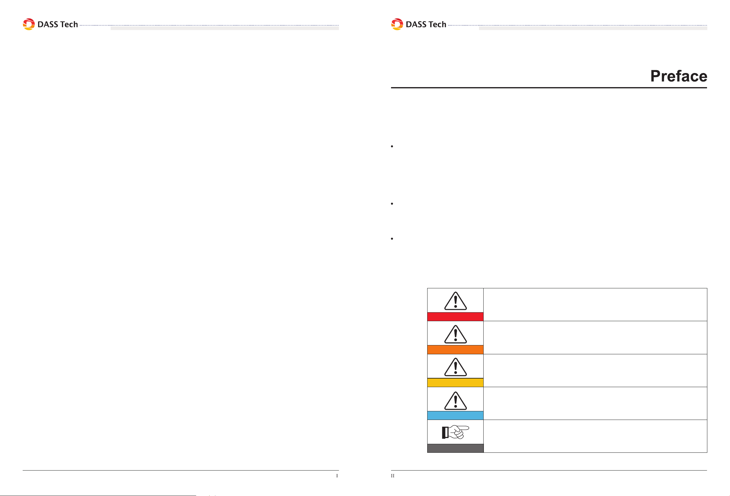
Symbols Used
This manual provides safety operation information and uses the symbol in order to ensure
personal and property security and use the inverter efficiently when operating the inverter.
You must understand these emphasized information to avoid the personal injury and
property loss. Please read the following symbols which used in this manual carefully.
This product manual describes the assembly, installation, commissioning, and maintenance of
the following inverters.
DSP 3320i-ODS, DSP 3325i-ODS, DSP 3330i-ODS, DSP 3333i-ODS
Keep this manual where it will be accessible at all times.
Danger indicates a hazardous situation which, if not avoided, will result
in death or serious injury.
Warning indicates a hazardous situation which, if not avoided, could
result in death or serious injury.
Caution indicates a hazardous situation, if not avoided, could result in
minor or moderate injury.
Attention indicates there are potential risks. If fail to prevent, may lead
to equipment cannot run normally or property damage.
Note provides tips that are valuable for the optimal operation of the
product. It can solve your problem and save your time if you read it
carefuly.
Danger
Warning
Caution
Attention
Note