EVVO E-75KTL User manual


E-80-136KTL User Manual
All copy reserved ©EVOLVE ENERGY GROUP Co., Ltd.
I
Preface.......................................................................................................................................................II
1. Basic Safety Information ....................................................................................................................- 1 -
1.1. Requirement for Installation and Maintenance ................................................... - 1 -
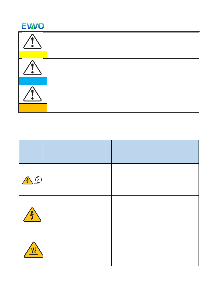
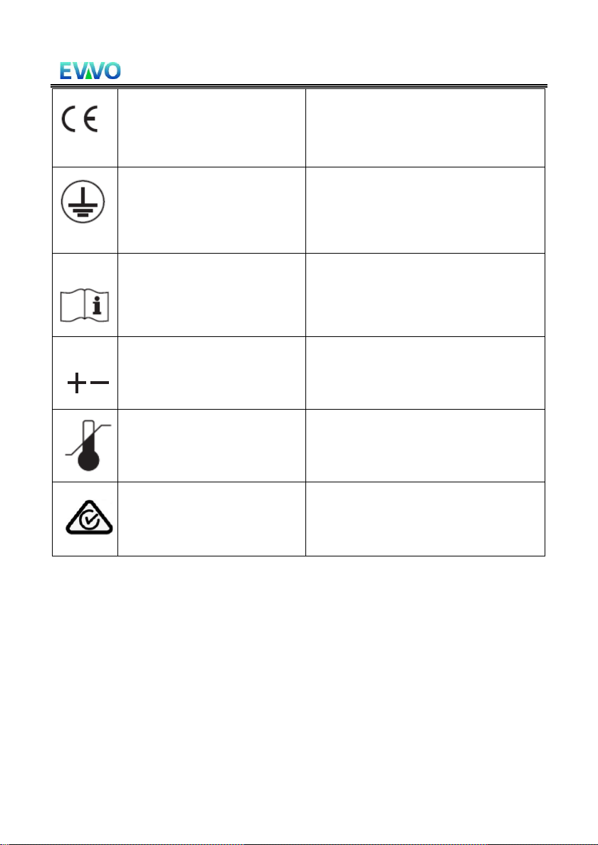
1.2. Symbols and signs................................................................................................ - 4 -
2. Product Characteristics ......................................................................................................................- 7 -
2.1. Intended Use........................................................................................................ - 7 -
2.2. Function Description.......................................................................................... - 10 -
2.3. Electrical block diagram ..................................................................................... - 11 -
2.4. Efficiency and derating curve............................................................................. - 12 -
3. Inverter Storage ...............................................................................................................................- 14 -
4. Installation .......................................................................................................................................- 15 -
4.1. Installation Process ............................................................................................ - 15 -
4.2. Checking Before Installation .............................................................................. - 15 -
4.3. Tools................................................................................................................... - 18 -
4.4. Determining the Installation Position ................................................................ - 20 -
4.5. Moving of inverter ............................................................................................. - 23 -
4.6. Installation ......................................................................................................... - 25 -
5. Electrical Connection .......................................................................................................................- 29 -
5.1. Electrical Connection ......................................................................................... - 30 -
5.2. Terminal Connector............................................................................................ - 30 -
5.3. Grounding Connection (PE)................................................................................ - 31 -
5.4. Connect grid side of inverter(AC-Output) .......................................................... - 33 -
5.5. Connect PV side of inverter(DC-Input)......................................................... - 39 -
5.6. Communication Connection .............................................................................. - 42 -
6. Commissioning of inverter ...............................................................................................................- 44 -
6.1. Cable Connection Inspection ............................................................................. - 44 -
6.2. Start Inverter...................................................................................................... - 45 -
7. Operation interface..........................................................................................................................- 46 -
7.1. Operation and Display Panel.............................................................................. - 46 -
7.2. Standard Interface ............................................................................................. - 47 -
7.3. Main Interface.................................................................................................... - 50 -
7.4. Updating Inverter Software ............................................................................... - 53 -
8. Trouble shooting and maintenance..................................................................................................- 56 -
8.1. Troubleshooting ................................................................................................. - 56 -
8.2. Maintenance...................................................................................................... - 65 -
9. Technical Data ..................................................................................................................................- 66 -
9.1. Input parameters (DC) ....................................................................................... - 66 -
9.2. Output Parameter (AC) ...................................................................................... - 68 -
9.3. Performance Parameter..................................................................................... - 69 -
9.4. General Data ...................................................................................................... - 70 -
10. Quality Assurance ..........................................................................................................................- 71 -

E-80-136KTL User Manual
All copy reserved ©EVOLVE ENERGY GROUP Co., Ltd.
II
Preface
Notice
The products, services or features you purchased shall be subject to the company's
commercial contracts and terms. All or part of the products and services described in
this document may not within the scope of your purchase. Unless additional terms
and conditions in your contract, the company does not make any statement or
guarantee on the contents of this document.
Save this Instruction
This manual must be considered as an integral part of the equipment. Customer can
print the electronic version to hard copy and keep properly for future reference.
Anyone who operates the device at any time must operate in accordance with the
requirements of this manual.
Copyright Declaration
The copyright of this manual belongs to EVOLVE ENERGY GROUP CO., LIMITED
Any corporation or individual should not plagiarize, partially copy or fully copy it
(including software, etc.), and no reproduction or distribution of it in any form or by
any means. All rights reserved. EVOLVE ENERG GROUP CO.,LTD reserves the right of
final interpretation. This manual is subject to change according to user’s or
customer’s feedback.

E-80-136KTL User Manual
All copy reserved ©EVOLVE ENERGY GROUP Co., Ltd.
III
⚫Outline
This manual is an integral part of E-75KTL to E-136KTL. It describes the assembly,
installation, commissioning, maintenance and failure of the product. Please read it
carefully before operating.
⚫Scope of Validity
This manual contains important instructions for:
E-75KTL E-80KTL E-100KTL E-110KTL
E-100KTL-HV E-125KTL-HV E-136KTL-HV
⚫Target Group
This manual is for qualified electricians. The tasks described in this manual only can
be performed by qualified electricians.
⚫Symbols Used
The following types of safety instruction and general information appear in this
document as described below:
“Danger”indicates a hazardous situation which, if not
avoided, will result in death or serious injury.
Danger
“Warning”indicates a hazardous situation which, if not
avoided, could result in death or serious injury
Warning
“Caution”indicates a hazardous situation which, if not
avoided, could result in minor or moderate injury
Caution
“Attention”indicates there are potential risks, if fail to
prevent, may lead to equipment cannot normally or property
damage.
Attention
“Note”provides additional information and tips that are
valuable for the optimal operation of the product.
Note

E-80-136KTL User Manual
Copyright ©EVOLVE ENERGY GROUP CO.,LTD
- 1 -
1.Basic Safety Information
Outlines of this Chapter
Please read the instruction carefully. Faulty operation may cause serious injury
or death.
Safety Instruction
Introduce the safety instruction during installation and operation of E- 75~136KTL
Symbols Instruction
This section gives an explanation of all the symbols shown on the inverter and on
the type label.
1.1. Requirement for Installation and Maintenance
Installation of E- 75-136KTL on-grid inverter must conform with laws, regulations,
codes and standards applicable in the jurisdiction.
Before installing and adjusting the produce, please read all of instructions, cautions
and warnings in this manual
Before connecting the product to the electrical utility grid, contact the local utility
company for allowance. Also, this connection must be made only by qualified
electrician.
If the failure persists, please contact the nearest authorized maintenance center. If
you don't know which service center is closest to you, please contact your local
distributor. Don't repair the product by yourself, which may lead serious injury or
damage.
Qualified Person
If you have any question or problem when you read the following
information, please contact EVOLVE ENERGY GROUP CO.,LTD.
Note

E-80-136KTL User Manual
Copyright ©EVOLVE ENERGY GROUP CO.,LTD
- 2 -
When inverter is working, it contains lethal voltages and become hot in some area.
Improper installation or mis-operation could cause serial damage and injury. To
reduce the risk of personal injury and to ensure the safe installation and operation
of the product, only a qualified electrician is allowed to execute transportation,
installation, commissioning and maintenance. EVOLVE ENERGY GROUP CO.,LTD does
not take any responsibility for the property destruction and personal injury because
of any incorrect use.
Label and Symbols
E- 75~136KTL has type label attached at the side of product which contain important
information and technical data, the type label must permanent attached to the
product.
E- 75~136KTL has warming symbol attached the product which contact information
of safety operation. The warming symbol must be permanently attached to the
product.
Installation location requirement
Please install the inverter according to the following section. Place inverter in an
appropriate bearing capacity objects (such as solid brick wall, or strength equivalent
mounting surface, etc.) and make sure inverter vertically placed. A proper
installation location must have enough space for fire engine access for maintenance
if faulty occur. Ensure the inverter is installed in a wall ventilated environment and
have enough air cooling cycle. Air humidity should be less than 90%.

E-80-136KTL User Manual
Copyright ©EVOLVE ENERGY GROUP CO.,LTD
- 3 -
Transportation Requirement
Inverter is in the good electrical and physical condition when shipped out from
factory. During transport, inverter must be placed in its original package or other
proper package. Transportation company should be responsible for any damage
during transport period.
If you find any packing problems that may cause the damage of inverter or any visible
damage, please notice the responsible transportation company immediately. You
can ask your installer or EVOLVE ENERGY GROUP CO.,LTD for help is necessary.
Electrical Connection
Please comply with all the current electrical regulations about accident prevention
in dealing with the current inverter.
Before the electrical connection, use opaque material to cover the PV
modules or disconnect PV string DC switch. PV arrays will produce
dangerous voltage on exposure under sun
Danger
All operation must be accomplished by certified electrical engineer
⚫Must be trained;
⚫Completely read the manual operation and understand all
information
Warming
Must get permission by local utility company before connecting to grid
and the connection must be done by certified electrical engineers
Attention
Operation
Touching the utility grid or the terminal conductors can lead to lethal
electric shock or fire!
Do not touch non-insulated cable ends, DC conductors and any live
components of the inverter.
Attention to any electrical relevant instruction and document.
Danger
Enclosure or internal components may get hot during operation. Do
not touch hot surface or wear insulated gloves.

E-80-136KTL User Manual
Copyright ©EVOLVE ENERGY GROUP CO.,LTD
- 4 -
Attention
Maintenance and repair
Before any repair work, turn OFF the AC circuit breaker between the
inverter and electrical grid first, then turn OFF the DC switch.
After turning OFF the AC circuit breaker and DC switch wait for at least
5 minutes before carrying out any maintenance or repair work.
Danger
Inverter should not work again until removing all faults. If any repair
work is required, please contact local authorized service centre.
Should not open the inverter cover without authorized permit, EVOLVE
ENERGY GROUP CO.,LTD does not take any responsibility for that.
Attention
EMC/Noise Level
Electromagnetic compatibility (EMC) refers to that on electrical equipment functions
in a given electromagnetic environment without any trouble or error, and impose no
unacceptable effect upon the environment. Therefore, EMC represents the quality
characters of an electrical equipment.
⚫The inherent noise-immune character: immunity to internal electrical noise
⚫External noise immunity: immunity to electromagnetic noise of external system
⚫Noise emission level: influence of electromagnetic emission upon environment
Electromagnetic radiation from inverter may be harmful to health!
Please do not continue to stay away from the inverter in less than 20cm
when inverter is working
Danger
1.2. Symbols and signs
High voltage of inverter may be harmful to health!
Only certified engineer can operate the product;
Juveniles, Disable, should not use this product;
Keep this product out of the reach of children;
Danger

E-80-136KTL User Manual
Copyright ©EVOLVE ENERGY GROUP CO.,LTD
- 5 -
Caution of burn injuries due to hot enclosure!
Only touch the screen and pressing key of the inverter while it is
working
Caution
PV array should be grounded in accordance to the requirements of the
local electrical grid company
Attention
Ensure the maximum DC voltage input is less than the maximum
inverter DC voltage (including in low temperature condition). Any
damage cause by overvoltage, E-SOLAR will not take the responsibility
including warranty
Warning
Signs on the Product and on the Type Label
E- 100KTL has some safety symbols on the inverter. Please read and fully understand
the content of the symbols before installation.
Symbols
Name
Explanation
This is a residual voltage in the
inverter!
After disconnecting DC side, there is
a residual voltage in the inverter,
operator should wait for 5 minutes to
ensure the capacitor is completely
discharged.
Caution of high voltage and
electric shock
The products operate at high
voltages. Prior to performing any work
on the product, disconnect the product
from voltage sources. All work on the
product must be carried out by
qualified persons only.
Caution of hot surface
The product can get hot during
operation. Avoid contact during
operation. Prior to performing any
work on the product, allow the product
to cool down sufficiently

E-80-136KTL User Manual
Copyright ©EVOLVE ENERGY GROUP CO.,LTD
- 6 -
Comply with the Conformite
Euroeenne (CE) Certification
The product complies with the CE
Certification
Grounding Terminal
This symbol indicates the position for
the connections of an additional
equipment grounding conductor
Observe the documentation
Read all documentation supplied with
the product before install
Positive pole and negative
pole
Positive pole and negative pole of the
input voltage (DC)
Temperature
Indicated the temperature allowance
range
RCM logo
RCM (Regulatory Compliance Mark)
The product complies with the
requirements of the applicable
Australian standards.

E-80-136KTL User Manual
Copyright ©EVOLVE ENERGY GROUP CO.,LTD
-7 -
2.Product Characteristics
Outlines of this Chapter
Product Dimensions
Introduce the field of use and the dimensions of the product
Function Description
Introduce working principle and internal components
Efficiency Curves
Introduce the efficiency curves of the product
2.1. Intended Use
E- 75~136KTL is a transformer less on grid PV inverter, that converters the direct
current of the PV array to the grid-compliant, three-phase current and feeds into the
utility grid.
Figures 2-1PV Grid-Tied System
E- 75~136KTL may only be operated with PV arrays (photovoltaic module and
cabling) for on grid condition. Do not use this product for any other or additional
purposes. Any damage or property loss due to any use of the product other than
described in this section, EVOLVE ENERGY GROUP CO.,LTD will not take the
responsibility. DC input of the product must be PV module, other source such like DC
sources, batteries will against the warranty condition and EVOLVE ENERGY GROUP
CO.,LTD will not take the responsibility.

E-80-136KTL User Manual
Copyright ©EVOLVE ENERGY GROUP CO.,LTD
- 8 -
Product Dimensions
The choice of optional parts of inverter should be made by a qualified
technician who knows the installation conditions clearly.
Dimensions Description
⚫E- 75~136KTL
L×W×H=995.5*663.5*368mm
Figure 2-2 Product front view and left view dimensions

E-80-136KTL User Manual
Copyright ©EVOLVE ENERGY GROUP CO.,LTD
- 9 -
Figure 2-3 Product back view and bracket dimensions
◆Labels on the equipment
Note: label must NOT be hidden with objects and extraneous parts (rags, boxes, equipment,
etc.,); they must be cleaned regularly and always kept visible.

E-80-136KTL User Manual
Copyright ©EVOLVE ENERGY GROUP CO.,LTD
- 10 -
2.2. Function Description
DC power generated by PV arrays is filtered through Input Board then enters Power
Board. Input Board also offer functions such as insulation impedance detection and
input DC voltage/ current detection. DC power is converted to AC power by Power
Board. AC power is filtered through Output Board then AC power is fed into the grid.
Output Board also offer functions such as grid voltage/ output current detection,
GFCI and output isolation relay. Control Board provides the auxiliary power, controls
the operation state of inverter, and shows the operation status by Display Board.
Display Board displays fault code when inverter is abnormal operation conditions. At
the same time, Control Board can trigger the replay to protect the internal
components.
Function Module
A. Energy management unit
Remote control to start/ shunt down inverter through an external control
B. Feeding reactive power into the grid
The inverter can produce reactive power thus to feed it into the grid through
the setting of the phase shift factor. Feed-in management can be controlled
directly by the grid company through a RS485 interface.

E-80-136KTL User Manual
Copyright ©EVOLVE ENERGY GROUP CO.,LTD
- 11 -
C. Limited the active power fed into grid
If enable the limited of active power function, inverter can limit the amount of
active power fed into the grid to the desired value (expressed as percentage)
D. Self-power reduction when grid is over frequency
If grid frequency is higher than the limited value, inverter will reduce the output
power to ensure the grid stability
E. Data transmission
Inverter or a group of inverters can be monitored remotely through an
advanced communication system based on RS485 interface or via Wi-Fi
F. Software update
USB interface for uploading the firmware, remotely uploading is available.
2.3. Electrical block diagram
E- 75~136KTL has 16-24 DC input strings. 8-12 MPPT trackers that converts the direct
current of PV array to grid-compliant, three phase current and feeds in into the utility
grid. Both DC and AC side has Surge Protection Device (SPD).

E-80-136KTL User Manual
Copyright ©EVOLVE ENERGY GROUP CO.,LTD
- 12 -
Schematic diagram
2.4. Efficiency and derating curve
90%
91%
92%
93%
94%
95%
96%
97%
98%
99%
100%
10% 20% 30% 40% 50% 60% 70% 80% 90% 100%
Efficiency[%]
% Of Rated Output Power
100KTL Efficiency curve
500V
600V
850V

E-80-136KTL User Manual
Copyright ©EVOLVE ENERGY GROUP CO.,LTD
- 13 -
90%
91%
92%
93%
94%
95%
96%
97%
98%
99%
100%
10% 20% 30% 40% 50% 60% 70% 80% 90% 100%
Efficiency[%]
% Of Rated Output Power
125KTL-HV Efficiency curve
600V
750V
850V
90%
92%
94%
96%
98%
100%
10% 20% 30% 40% 50% 60% 70% 80% 90% 100%
Efficiency[%]
% Of Rated Output Power
136KTL-HV Efficiency curve
600V
750V
850V

E-80-136KTL User Manual
Copyright ©EVOLVE ENERGY GROUP CO.,LTD
- 14 -
3.Inverter Storage
If inverter is not installed immediately, storage condition needs to meet below
requirements:
⚫Place inverter into the original package and leave desiccant inside, sealed tight
with taps.
⚫Keep the storage temperature around -40℃~70℃, Relative humidity 0~95%,
no condensation
Figure 3-1Storage temperature and humidity
⚫The maximum stacking layer number cannot exceed 3 layers.
⚫If the inverter be stored for more than half years, the inverter needs to be fully
examined and tested by qualified service or technical personnel before using.

E-80-136KTL User Manual
Copyright ©EVOLVE ENERGY GROUP CO.,LTD
- 15 -
4.Installation
Outlines of this Chapter
This topic describes how to install this product, please read carefully before
install.
Do NOT install the product on flammable material
Do NOT store this product in potentially explosive atmospheres
Dangers
The enclosure and heat sink will get hot during operation, please
do not mount the product at easy to reach location
Caution
Consider the weight of this product when transport and moving
Choose an appropriate mounting position and surface
At least two persons for installation
Attention
4.1. Installation Process
4.2. Checking Before Installation
Checking Outer Packing Materials
Before unpacking, please check the condition of the outer package materials if any
damage found, such as holes, cracks, please not unpack the product, contact your
distributor immediately. Recommend installing the product within 24 hours after
unpacking the package.

E-80-136KTL User Manual
Copyright ©EVOLVE ENERGY GROUP CO.,LTD
- 16 -
Checking Deliverable
After unpacking, please check according to following table, to see whether all the
parts were included in the packing, please contact your distributor immediately if
anything missing or damage.
Figure 4-1Components and mechanical parts that inside the package
No
Pictures
Description
Quantity
1
E- 75-136KTL
1 PCS
2
Rear Panel
1 PCS
3
PV+ input connector
75KTL 16PCS
80KTL 16PCS
100KTL 20PCS
110KTL 20PCS
125KTL 20PCS
136KTL 24PCS
4
PV- input connector
75KTL 16PCS
80KTL 16PCS
100KTL 20PCS
110KTL 20PCS
125KTL 20PCS
136KTL 24PCS
5
PV+ metal pin
75KTL 16PCS
80KTL 16PCS
100KTL 20PCS
110KTL 20PCS
125KTL 20PCS
136KTL 24PCS
This manual suits for next models
5
Table of contents
Other EVVO Inverter manuals
Popular Inverter manuals by other brands

Generac Power Systems
Generac Power Systems 04673-2 Installation and owner's manual

Sunerg Solar Energy
Sunerg Solar Energy TENDAEVO 1T installation manual

Active
Active AGi3500 user manual

Mitsubishi Electric
Mitsubishi Electric FR-F720P-0.75K to 110K instruction manual

XTline
XTline XT103160 user manual

Eurotops
Eurotops 39 581 instruction manual