EWK I User manual
http://www.ewk.eu
Maintenance Manual
Manuel d’Entretien
Betriebs- und Wartungsanleitung
EWK-I Closed Circuit Towers
Tours Fermées
Geschlossene Kühltürme
REV.9 - 14/04/2016

English – Anglais -
Englisch
1.- INTRODUCTION
2.-
DESCRIPTION AND DESIGN FEATURES
2.1.-Tower components
2.2.-Operating principle
2.3.-Type of design
3.-
HANDLING, ASSEMBLING AND CONNECTING THE
ELEMENTS
3.1.-Handling and unloading
3.2.-Assembling and erecting on site
3.2.1.- Assembly of towers
3.2.2.-
General observations related to towers sites
3.3.-Tower connections
4.- OPERATION
4.1.-Operating limits
4.2.-Initial start-
up or starting after a long period out of
service
4.3.- Stop periods of less than 8 days
4.4.-Safety instructions
4.4.1.-
Welding and grinding operations
4.4.2.- Access to the cooling tower
4.4.3.- Water connections
4.4.4.-
Operation at low temperatures
5.- MAINTENANCE
5.1.-General
5.2.-Maintenance tasks
5.2.1.- Filter
5.2.2.- Fill
5.2.3.- Drift eliminator
5.2.4.- Spray nozzles
5.2.5.- Float valve
5.2.6.- Motor and reducer
5.2.7.- Fan
5.2.8.- Louvers
5.2.9.- Plate heat exchanger
5.2.10.- Y Filter
5.2.11.- Impulse pump
6.- TROUBLESHOOTING
7.- LIST OF COMPONENTS
8.-
COMPLEMENTARY ACCESSORIES FOR THE TOWERS
8.1.-Electric resistor
8.2.-Thermostat for the electric
resistor
8.3.-Thermostat for the fan
8.4.-
Ladders and platforms (only for large models)
8.5.- Exhaust silencer
8.6.- Vibration switch
9.-WATER TREATMENT
Englisch
DESCRIPTION AND DESIGN FEATURES
HANDLING, ASSEMBLING AND CONNECTING THE
General observations related to towers sites
up or starting after a long period out of
Welding and grinding operations
Operation at low temperatures
COMPLEMENTARY ACCESSORIES FOR THE TOWERS
resistor
Ladders and platforms (only for large models)
Français–
French
1.- INTRODUCTION
2.-
DESCRIPTION ET CARACTÉRISTIQUES DE
CONSTRUCTION
2.1.-Composants des tours
2.2.-
Principe de fonctionnement
2.3.-Type de construction
3.-
MANUTENTION ET MONTAGE
3.1.-Manutention de
déchargement
3.2.-
Montage et implantation sur site
3.2.1.-
Montage des tours
3.2.2.-
Observations générales pour l’implantation
des tours
3.3.-
Raccordement de la tour
4.- FONCTIONNEMENT
4.1.-
Limites de fonctionnement
4.2.-
Mise en fonctionnement initiale ou après de longues
périodes d’inactivité
4.3.- Arrêts
d’installation inférieurs à 8 jours
4.4.-
Instructions de sécurité
4.4.1.-
Travaux de soudure et meulage
4.4.2.-
Accès à la tour de refroidissement
4.4.3.-
Raccordement d’eau
4.4.4.-
Fonctionnement à basses températures
5.- ENTRETIEN
5.1.-Entretien général
5.2.-Tâches d’entretien
5.2.1.- Filtre
5.2.2.- Garnissage
5.2.3.- Séparateur
de gouttelettes
5.2.4.- Tuyères
de pulvérisation
5.2.5.- Vanne à flotteur
5.2.6.- Moteur
et réducteur
5.2.7.- Ventilateur
5.2.8.- Persiennes
5.2.9.- Echangeur
5.2.10.- Filtre en Y
5.2.11.-
Pompe de refoulement
6.- RECHERCHE DE PANNES
7.- LISTE DE COMPOSANTS
8.-
ACCESOIRES COMPLÉMENTAIRES DES TOURS
8.1.-Resistance électrique
8.2.-
Thermostat pour la résistance
8.3.-
Thermostat pour le ventilateur
8.4.-
Échelles et plateforme (pour les gran
8.5.-
Silencieux d’évacuation
8.6.-
Interrupteur de vibrations
9.- TRAITEMENT DE L’EAU
Pag./Seite 2
French
- Französisch
DESCRIPTION ET CARACTÉRISTIQUES DE
Principe de fonctionnement
MANUTENTION ET MONTAGE
déchargement
Montage et implantation sur site
Montage des tours
Observations générales pour l’implantation
Raccordement de la tour
Limites de fonctionnement
Mise en fonctionnement initiale ou après de longues
d’installation inférieurs à 8 jours
Instructions de sécurité
Travaux de soudure et meulage
Accès à la tour de refroidissement
Raccordement d’eau
Fonctionnement à basses températures
de gouttelettes
de pulvérisation
et réducteur
Pompe de refoulement
ACCESOIRES COMPLÉMENTAIRES DES TOURS
Thermostat pour la résistance
électrique
Thermostat pour le ventilateur
Échelles et plateforme (pour les gran
ds modèles)
Silencieux d’évacuation
Interrupteur de vibrations

German– Allemand -
Deutsch
1.- EINFÜHRUNG
2.-
BESCHREIBUNG UND KONSTRUKTIONS
MERKMALE
2.1.-Komponenten der Kühltürme
2.2.-Funktionsprinzip
2.3.-Bauart
3.-
HANDHABUNG, MONTAGE UND ANSCHLUSS
3.1.-Handhabung und Entladen
3.2.-Montage und Aufstellung
3.2.1.- Montage der Kühltürme
3.2.2.-
Allgemeine Bemerkungen zur
Aufstellung der Kühltürme
3.3.-Anschluss des Kühlturms
4.- BETRIEB
4.1.-Betriebsgrenzwerte
4.2.-Erste Inbetriebnah
me oder Inbetriebnahme
nach längeren Stillstandzeiten
4.3.- Stillstand kürzer als 8 Tage
4.4.-Sicherheitshinweise
4.4.1.- Schweiß-
und Schleifarbeiten
4.4.2.- Zugang zum Kühlturm
4.4.3.- Wasseranschlüsse
4.4.4.-
Betrieb bei niedrigen Temperaturen
5.- WARTUNG
5.1.-Allgemeine Wartung
5.2.-Wartungsarbeiten
5.2.1.- Filter
5.2.2.- Füllkörpereinsatz
5.2.3.- Tropfenabscheider
5.2.4.- Sprühdüsen
5.2.5.- Schwimmerventil
5.2.6.-
Motor und Getriebe (sofern im Lieferumfang
enthalten)
5.2.7.- Ventilator
5.2.8.- Gitterkassetten
5.2.9.- Wärmetauscher
5.2.10.- Y-Filter
5.2.11.- Umwälzpumpe
6.- BEHEBUNG VON STÖRUNGEN
7.- LISTE DER BAUTEILE
8.- ZUSATZAUSRÜSTUNG FÜR
DIE KÜHLTÜRME
8.1.-Elektrischer Widerstand
8.2.-
Thermostat für den elektrischen Widerstand
8.3.-Thermostat für den Ventilator
8.4.-
Leitern und Zugangsplattform (nur für große
Modelle)
8.5.-Auslassschalldämpfer
8.5.-Vibrationsschalter
9.- WASSERAUFBEREITUNG
Deutsch
BESCHREIBUNG UND KONSTRUKTIONS
-
HANDHABUNG, MONTAGE UND ANSCHLUSS
Allgemeine Bemerkungen zur
me oder Inbetriebnahme
und Schleifarbeiten
Betrieb bei niedrigen Temperaturen
Motor und Getriebe (sofern im Lieferumfang
DIE KÜHLTÜRME
Thermostat für den elektrischen Widerstand
Leitern und Zugangsplattform (nur für große
................................
................................
................................
................................
................................
................................
................................
................................
................................
................................
................................
................................
................................
................................
................................
................................
................................
................................
................................
................................
................................
................................
................................
................................
................................
................................
................................
................................
................................
................................
................................
................................
................................
................................
................................
................................
................................
................................
................................
................................
................................
................................
................................
................................
................................
................................
................................
................................
................................
................................
................................
................................
................................
................................
................................
................................
................................
................................
................................
................................
................................
................................
................................
................................
................................
................................
................................
................................
................................
................................
................................
................................
................................
................................
................................
................................
................................
................................
................................
................................
................................
................................
................................
................................
................................
................................
................................
................................
Pag./Seite 3
................................
......................... 4
................................
......................... 4
................................
......................... 4
................................
......................... 6
................................
......................... 6
................................
.........................12
................................
.........................12
................................
.........................16
................................
.........................16
................................
.........................24
................................
.........................30
................................
.........................32
................................
.........................32
................................
.........................32
................................
.........................32
................................
.........................34
................................
.........................36
................................
.........................36
................................
.........................36
................................
.........................38
................................
.........................42
................................
.........................42
................................
.........................44
................................
.........................46
................................
.........................46
................................
.........................48
................................
.........................50
................................
.........................50
................................
.........................52
................................
.........................54
................................
.........................54
................................
.........................54
................................
.........................58
................................
.........................58
................................
.........................60
................................
.........................62
................................
.........................64
................................
.........................64
................................
.........................64
................................
.........................64
................................
.........................64
................................
.........................66
................................
.................
66
................................
.........................
68
English – Anglais -
Englisch
1.- INTRODUCTION
The
se service instructions contain
information on handling, assembly, operation,
connections, start up and servicing of
type cooling towers.
At the same time instructions are given on
the procedure to solve eventual faults which
could
result in service interruption. Supplier
declines any liability on damages originated for
not following these indications.
2.-
DESCRIPTION AND DESIGN FEATURES
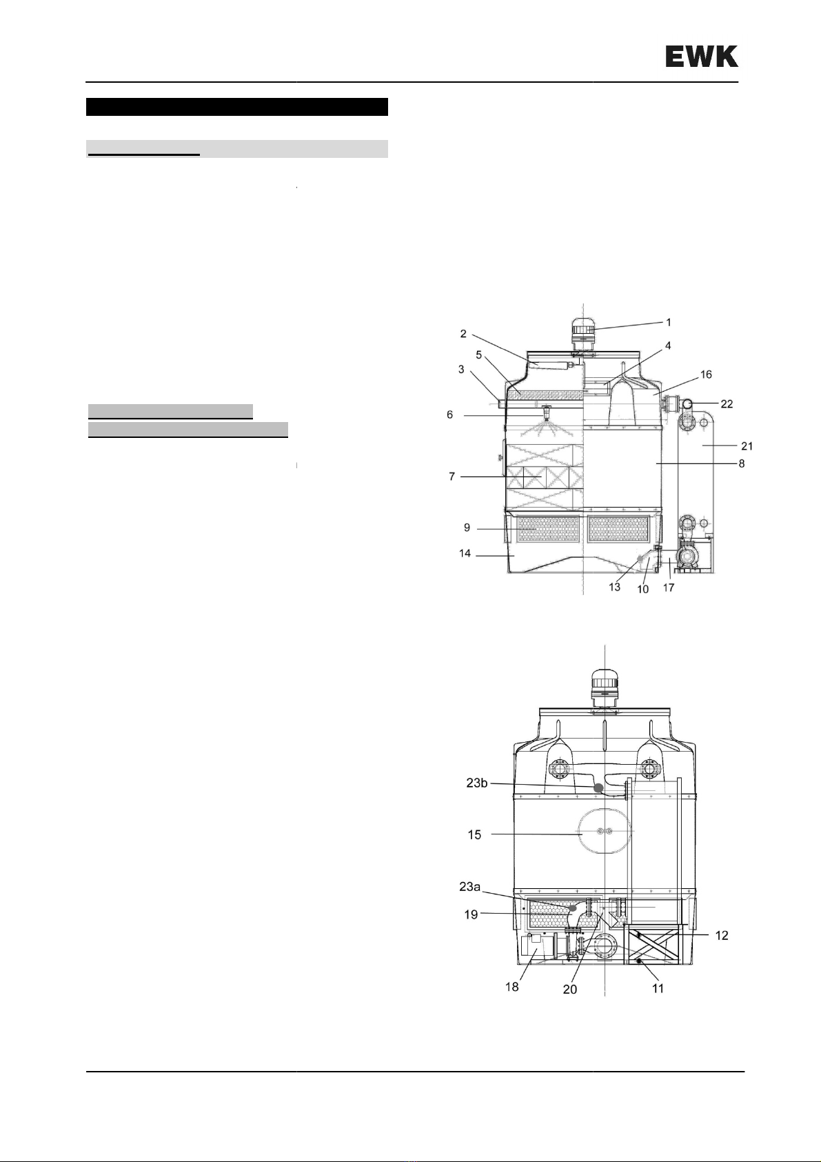
2.1.- Tower components
Figures 1 and 2 show
the main components
that are included in type EWK-I
towers. For this
series types, the square or rectangular shape of
the base offers a saving of space in installations
with several towers in series.
1. Fan motor
2. Fan
3. Distribution pipe
4. Drift el
iminator replacing window
5. Drift eliminator
6. Spray nozzles
7. Fill
8. Casing
9. Louvers
10. Filter
11. Drain plug
12. Overflow
13. Float valve
14. Collecting basin
15. Manhole cover
16. Upper cap
17. Aspiration pipe
18. Centrifugal pump
19. Impulse pipe
20. Y filter
21. Plate heat exchanger
22. Header
23a. Impulsion manometer
23b. Main header manometer
Englisch
se service instructions contain
information on handling, assembly, operation,
connections, start up and servicing of
EWK-I
At the same time instructions are given on
the procedure to solve eventual faults which
result in service interruption. Supplier
declines any liability on damages originated for
DESCRIPTION AND DESIGN FEATURES
the main components
towers. For this
series types, the square or rectangular shape of
the base offers a saving of space in installations
iminator replacing window
Français–
French
1.- INTRODUCTION
Ces instructions de service contiennent des
informations sur la manipulation, le montage, les
connexions, la mise en service et l´entretien des
tours de refroidissement type EWK
Aussi on donne des instructions sur la façon
de résoudre de possibles pannes qui pourraient
conduire à une interruption du service. Le
fabricant décline toute responsab
dégâts occasionnés par l´inaccomplissement de
ces indications.
2.-
DESCRIPTION ET CARACTÉRISTIQUES
DE CONSTRUCTION
2.1.-
Composants des tours
Sur les figures 1
et 2
éléments principaux qui font partie des tours
type EWK-I
. La forme carrée ou rectangulaire de
la base, pour les types de cette série, offre une
considérable économie d´espace dans les
installations où sont placées plusieurs tours en
batterie.
1. Moteur du ventilateur
2. Ventilateur
3. Tuyaux de distribution
4.
Trappe pour changer le séparateur de goutes
5. Séparateurs de gouttelettes
6.
Tuyères de pulvérisation
7. Garnissage
8. Carcasse
9. Persiennes
10. Filtre
11. Bouchon pour
drainage
12. Déversoir
13. Vanne à flotteur
14. Bassin ramasseur
15. Trou d´homme
16. Capuchon
17. Tubulure d’entrée
18. Pompe centrifuge
19
. Tubulure d’impulsion
20. Filtre en Y
21
. Echangeur de chaleur
22. Collecteur d’entrée
23a. Manomètre refoulement
23b
Manomètre collecteur principal
Pag./Seite 4
French
- Französisch
Ces instructions de service contiennent des
informations sur la manipulation, le montage, les
connexions, la mise en service et l´entretien des
tours de refroidissement type EWK
-I.
Aussi on donne des instructions sur la façon
de résoudre de possibles pannes qui pourraient
conduire à une interruption du service. Le
fabricant décline toute responsab
ilité sur les
dégâts occasionnés par l´inaccomplissement de
DESCRIPTION ET CARACTÉRISTIQUES
Composants des tours
et 2
on peut apprécier les
éléments principaux qui font partie des tours
. La forme carrée ou rectangulaire de
la base, pour les types de cette série, offre une
considérable économie d´espace dans les
installations où sont placées plusieurs tours en
3. Tuyaux de distribution
Trappe pour changer le séparateur de goutes
5. Séparateurs de gouttelettes
Tuyères de pulvérisation
drainage
. Tubulure d’impulsion
. Echangeur de chaleur
23a. Manomètre refoulement
pompe
Manomètre collecteur principal
German– Allemand -
Deutsch
1.- EINFÜHRUNG
Die vorliegende Betriebs
Wartungsanleitung beinhaltet Informationen
über die Handhabung, die Installation, den
Anschluss sowie die Inbetriebnahme und die
Wartung
der Kühltürme der Baureihe EWK
Darüber hinaus werden Anweisungen zur
Behebung möglicher Störungen gegeben, die zu
Ausfallzeiten führen können. Der Hersteller lehnt
jegliche Haftung für Schäden ab, die durch
Nichteinhaltung der vorliegenden Hinweise
entstehen.
2.- BESCHREIBUNG UND
KONSTRUKTIONSMERKMALE
2.1.
Komponenten der Kühltürme
Die Abbildungen 1-A und 1
-
Hauptbestandteile der Türme aus der Baureihe
EWK-
I. Die quadratische oder rechteckige Form
der Grundplatte für die Kühlerarten aus dieser
Baureihe bietet eine erhebl
iche Platzersparnis
bei Installationen, in denen verschiedene
Kühltürme parallel nebeneinander angeordnet
werden.
1. Ventilatormotor
2. Ventilator
3. Verteilrohr
4. W
artungsöffnung für Tropfenabscheider
5. Tropfenabscheider
6. Sprühdüsen
7. Füllkörpereinsatz
8. Gehäuse
9. Gitterkassetten
10. Filter
11. Ablassstopfen
12. Überlauföffnung
13. Schwimmerventil
14. Wassersammelwanne
15. Inspektionsöffnung
16. Obere Abdeckung
17. Ansaugrohr
18. Zentrifugalpumpe
19. Pumprohr
20. Y-Filter
21. Wärmetauscher
22. Einlassverteiler
23a.
Manometer Druckseite (zwischen Pumpe
und Plattenwärmetauscher)
23b.
Manometer Wassereintrittsseite (zwischen
Plattenwärmetauscher und Wassereintritt)
Deutsch
Die vorliegende Betriebs
- und
Wartungsanleitung beinhaltet Informationen
über die Handhabung, die Installation, den
Anschluss sowie die Inbetriebnahme und die
der Kühltürme der Baureihe EWK
-I.
Darüber hinaus werden Anweisungen zur
Behebung möglicher Störungen gegeben, die zu
Ausfallzeiten führen können. Der Hersteller lehnt
jegliche Haftung für Schäden ab, die durch
Nichteinhaltung der vorliegenden Hinweise
Komponenten der Kühltürme
-
B zeigen die
Hauptbestandteile der Türme aus der Baureihe
I. Die quadratische oder rechteckige Form
der Grundplatte für die Kühlerarten aus dieser
iche Platzersparnis
bei Installationen, in denen verschiedene
Kühltürme parallel nebeneinander angeordnet
artungsöffnung für Tropfenabscheider
Manometer Druckseite (zwischen Pumpe
Manometer Wassereintrittsseite (zwischen
Plattenwärmetauscher und Wassereintritt)
Fig./Abb.
Fig./Abb.
Pag./Seite 5
Fig./Abb.
1-A
Fig./Abb.
1-B
English – Anglais -
Englisch
2.2.- Operating principle
In a cooling tower air and water are put in
intensive contact, therefore producing an
evaporation of a portion of the water, which
means that the necessary heat to evaporate
water is obtained in this case from the
water circuit.
By means of the distribution pipes and the
spray nozzles, located in the top of the tower,
the return hot water is sprayed proportionally
over the fill, which forms the heat exchange
surface, and making the water flow downwards
thro
ugh these channels. At the same time and
by means of the axial fan, outer air is sucked in,
and impelled upwards opposite to the water
path, creating its cooling. The flow of evaporated
water is compensated by the addition of fresh
water.
In type EWK-I
towers, the heat rejection, from
the process, is exchanged on the plate heat
exchanger, having heat transfer and not mass
transfer.
Afterwards the water coming from this
exchange is cooled as previously explained.
2.3.- Type of design
The design of cooling water towers with
synthetic resins, a first execution by
differs mainly from conventional designs by its
substantial cooling capacity in a reduced amount
of space. The lightness in weight and small
space required make the inst
allation of these
towers easier on rooftops, terraces, pedestals
and other mounting sites. In general, no
reinforcing of the base will be necessary to
support towers.
The design features of the different elements
composing EWK-I
cooling towers are:
Englisch
In a cooling tower air and water are put in
intensive contact, therefore producing an
evaporation of a portion of the water, which
means that the necessary heat to evaporate
water is obtained in this case from the
cooling
By means of the distribution pipes and the
spray nozzles, located in the top of the tower,
the return hot water is sprayed proportionally
over the fill, which forms the heat exchange
surface, and making the water flow downwards
ugh these channels. At the same time and
by means of the axial fan, outer air is sucked in,
and impelled upwards opposite to the water
path, creating its cooling. The flow of evaporated
water is compensated by the addition of fresh
towers, the heat rejection, from
the process, is exchanged on the plate heat
exchanger, having heat transfer and not mass
Afterwards the water coming from this
exchange is cooled as previously explained.
The design of cooling water towers with
synthetic resins, a first execution by
SULZER,
differs mainly from conventional designs by its
substantial cooling capacity in a reduced amount
of space. The lightness in weight and small
allation of these
towers easier on rooftops, terraces, pedestals
and other mounting sites. In general, no
reinforcing of the base will be necessary to
The design features of the different elements
cooling towers are:
Français–
French
2.2.-
Principe de fonctionnement
Dans une tour de refroidissement sont mis en
contact intensif l´air et l´eau, ce qui produit une
évaporation d´une partie de celle
la chaleur nécessaire pour évaporer
obtenue dans ce cas avec la même eau du
circuit de refroidissement.
Au moyen des tuyauteries de distribution et
des tuyères, situées dans la partie supérieure de
la tour, l´eau chaude de retour est pulvérisée
proportionnellement sur le garnissag
la superficie d’échange de chaleur, garnissages
aux travers desquels elle glisse vers le bas. En
même temps et à l´aide du ventilateur axial, l´air
extérieur est aspiré et poussé vers le haut en
sens contraire de la trajectoire de l´eau, ce qu
cause son refroidissement. La quantité d´eau
évaporée est restituée par l´apport d´eau
fraîche.
Dans la tour EWK I l’échange de chaleur,
(composante du
procès
l’échangeur à plaques, qui réalise un transfert
d’énergie et non un
transfert de masse.
l’eau procédant de cet échange est refroidie
comme ce qui précède.
2.3.-
Type de construction
La construction des tours de refroidissement
avec des résines synthétiques, réalisée pour la
première fois par SULZER, se différencie
principalement des constructions
conventionnelles, par sa grande capacité de
refroidissement dans un espace relativement
petit. Le faible poids et le peu d´espace
demandé facilitent l´installation de ces tours sur
des toits, terrasses, armatures et autres
montage, sans que, généralement, il soit
nécessaire de renforcer la base choisie pour les
supporter.
Les caractéristiques de construction des
différents éléments qui composent les tours de
réfrigération EWK-I
sont:
Pag./Seite 6
French
- Französisch
Principe de fonctionnement
Dans une tour de refroidissement sont mis en
contact intensif l´air et l´eau, ce qui produit une
évaporation d´une partie de celle
-ci; c´est à dire,
la chaleur nécessaire pour évaporer
l´eau est
obtenue dans ce cas avec la même eau du
circuit de refroidissement.
Au moyen des tuyauteries de distribution et
des tuyères, situées dans la partie supérieure de
la tour, l´eau chaude de retour est pulvérisée
proportionnellement sur le garnissag
e, qui forme
la superficie d’échange de chaleur, garnissages
aux travers desquels elle glisse vers le bas. En
même temps et à l´aide du ventilateur axial, l´air
extérieur est aspiré et poussé vers le haut en
sens contraire de la trajectoire de l´eau, ce qu
i
cause son refroidissement. La quantité d´eau
évaporée est restituée par l´apport d´eau
Dans la tour EWK I l’échange de chaleur,
procès
), s’effectue grâce à
l’échangeur à plaques, qui réalise un transfert
transfert de masse.
Après,
l’eau procédant de cet échange est refroidie
Type de construction
La construction des tours de refroidissement
avec des résines synthétiques, réalisée pour la
première fois par SULZER, se différencie
principalement des constructions
conventionnelles, par sa grande capacité de
refroidissement dans un espace relativement
petit. Le faible poids et le peu d´espace
demandé facilitent l´installation de ces tours sur
des toits, terrasses, armatures et autres
lieux de
montage, sans que, généralement, il soit
nécessaire de renforcer la base choisie pour les
Les caractéristiques de construction des
différents éléments qui composent les tours de
sont:
German– Allemand -
Deutsch
2.2.- Funktionsprinzip
In einem Kühlturm werden Luft und Wasser
intensiv miteinander in Kontakt gebracht,
wodurch ein Teil des Wassers verdunstet. Die
benötigte Verdunstungswärme erhält man in
diesem Fall vom Wasser aus dem Kühlkreislauf.
Über die oberhalb des Kühlturms
angebrachten Verteilrohre und Sprühdüsen wird
das warme Rücklaufwasser proportional über
den Füllkörpereinsatz, der die
Wärmeaustauschfläche bildet, gesprüht. Danach
fließt das Wasser durch die Füllkörperkanäle
nach unten. G
leichzeitig wird mit Hilfe des
Axialventilators die Außenluft in Gegenrichtung
zum Wasserlauf angesaugt und nach oben
befördert, wodurch das Wasser gekühlt wird. Die
verdunstete Wassermenge wird durch die
Zugabe von Frischwasser ersetzt.
In dem Kühlturm
aus der Baureihe EWK
erfolgt der Austausch der prozesseigenen
Wärme im Plattenwärmetauscher, wodurch eine
Übertragung von Energie und nicht von
thermischer Masse entsteht. Im Anschluss
daran kühlt das aus diesem Wärmeaustausch
erzeugte Wasser wie zuvor b
eschrieben ab.
2.3.-Bauart
Mit Kunstharz gefertigte Kühltürme wurden
zum ersten Mal von SULZER hergestellt. Sie
unterscheiden sich von den herkömmlichen
Geräten in erster Linie durch ihre große
Kühlleistung auf relativ kleinem Raum. Ihr
leichtes Gewicht
und der geringe Platzbedarf
machen die Montage dieser Türme auf Dächern,
Terrassen, Metallstrukturen und an anderen
Montagestätten möglich, ohne dass im
allgemeinen eine Verstärkung des gewählten
Fundamentes zum Tragen der Türme notwendig
wird.
Die Konstr
uktionsmerkmale der
verschiedenen Elemente, aus denen die
Kühltürme der Baureihe EWK-
I bestehen, sind:
Deutsch
In einem Kühlturm werden Luft und Wasser
intensiv miteinander in Kontakt gebracht,
wodurch ein Teil des Wassers verdunstet. Die
benötigte Verdunstungswärme erhält man in
diesem Fall vom Wasser aus dem Kühlkreislauf.
Über die oberhalb des Kühlturms
angebrachten Verteilrohre und Sprühdüsen wird
das warme Rücklaufwasser proportional über
den Füllkörpereinsatz, der die
Wärmeaustauschfläche bildet, gesprüht. Danach
fließt das Wasser durch die Füllkörperkanäle
leichzeitig wird mit Hilfe des
Axialventilators die Außenluft in Gegenrichtung
zum Wasserlauf angesaugt und nach oben
befördert, wodurch das Wasser gekühlt wird. Die
verdunstete Wassermenge wird durch die
Zugabe von Frischwasser ersetzt.
aus der Baureihe EWK
-I
erfolgt der Austausch der prozesseigenen
Wärme im Plattenwärmetauscher, wodurch eine
Übertragung von Energie und nicht von
thermischer Masse entsteht. Im Anschluss
daran kühlt das aus diesem Wärmeaustausch
eschrieben ab.
Mit Kunstharz gefertigte Kühltürme wurden
zum ersten Mal von SULZER hergestellt. Sie
unterscheiden sich von den herkömmlichen
Geräten in erster Linie durch ihre große
Kühlleistung auf relativ kleinem Raum. Ihr
und der geringe Platzbedarf
machen die Montage dieser Türme auf Dächern,
Terrassen, Metallstrukturen und an anderen
Montagestätten möglich, ohne dass im
allgemeinen eine Verstärkung des gewählten
Fundamentes zum Tragen der Türme notwendig
uktionsmerkmale der
verschiedenen Elemente, aus denen die
I bestehen, sind:
Pag./Seite 7
English – Anglais -
Englisch
– Casings:
All the casings for this series type
are made in fiberglass-
reinforced polyester,
being wholly stables to
the influence of salts
and to other more or less aggressive
elements in the cooling water. They are also
stable to all kind of ambient conditions,
enabling them to withstand temperatures
from -40º C up to +130º C.
–
Fill: The fill serves as heat exchang
in which the cooling process by evaporation
of a part of the cooling water takes part. The
saving obtained in cooling water consumption
is based in making use of the evaporation
effect applied to the towers. The fill is made
of PVC or polypropyl
ene, manufactured in
the EWK Spain factory in
Fuente el Saz
WARNING: The use of a fill not manufactured
or authorized by EWK
can cause a
alteration of the cooling tower operation.
–
Fan: The towers are provided with fans, of
very low noise
level and easy maintenance.
These fans are static and dynamically
balanced in factory. The set composed by
and electric motor, directly coupled to
is mounted on the upper part of the
together with a fastening ring in
steel.
–
Water distribution System: The return hot
water distribution on the fill is made by
means of spray nozzles, made of synthetic
resins. The ample ports with which they are
fitted guarantee their correct operation and
eliminate in practice every possibilit
clogging. Depending on the types, the
is fitted with one or several spray
–
Fan motor: The motors for the fans used on
the cooling towers are three-
phase and
part of the fan blades and of the fastening
ring. They are manufactured
enclosed design against water
can be supplied with
commutable
Englisch
All the casings for this series type
reinforced polyester,
the influence of salts
and to other more or less aggressive
elements in the cooling water. They are also
stable to all kind of ambient conditions,
enabling them to withstand temperatures
Fill: The fill serves as heat exchang
e surface,
in which the cooling process by evaporation
of a part of the cooling water takes part. The
saving obtained in cooling water consumption
is based in making use of the evaporation
effect applied to the towers. The fill is made
ene, manufactured in
Fuente el Saz
.
WARNING: The use of a fill not manufactured
can cause a
severe
alteration of the cooling tower operation.
Fan: The towers are provided with fans, of
level and easy maintenance.
These fans are static and dynamically
balanced in factory. The set composed by
fan
and electric motor, directly coupled to
the fan,
is mounted on the upper part of the
casing,
together with a fastening ring in
galvanized
Water distribution System: The return hot
water distribution on the fill is made by
means of spray nozzles, made of synthetic
resins. The ample ports with which they are
fitted guarantee their correct operation and
eliminate in practice every possibilit
y of
clogging. Depending on the types, the
tower
is fitted with one or several spray
nozzles.
Fan motor: The motors for the fans used on
phase and
form
part of the fan blades and of the fastening
ring. They are manufactured
in totally
enclosed design against water
sprays and
commutable
poles.
Français–
French
–
Carcasse: Les carcasses de tous les types
de cette série, sont réalisées en polyester
armé de fibre de verre et sont
stables à l´influence des sels et autres
éléments plus ou moins agressifs contenus
dans l´eau de circulation. Elles sont aussi
stables à toute sorte de conditions
météorologiques et peuvent résister à des
températures de -
40ºC jusqu´à + 130ºC.
-
Garnissage: Le garnissage constitue la
superficie d´échange de chaleur, où est
réalisé le procédé de refroidissement par
évaporation d´une partie de l´eau en
circulation. L´économie obtenue dans la
consommation de l´eau de refroidissement,
est basée sur
le profit de l´effet d’évaporation
appliqué aux tours. Le garnissage est
élaboré en PVC ou
l´usine de EWK
Espagne à
ATTENTION: L´utilisation de garnissages
non fabriqués ou non autorisés par
peut altérer gravement l
la tour de refroidissement.
–
Ventilateur: Les ventilateurs dont sont
pourvues les tours de cette série, sont de
très faible sonorité et très simple d´entretien.
Ces ventilateurs sont équilibrés à l´usine
d´une façon statique et
L´ensemble formé par le ventilateur et le
moteur, raccordé directement à celui
monté dans la partie supérieure de la
carcasse conjointement à un anneau de
fixation
en acier galvanisé.
–
Système distributeur d´eau: La distribution de
l´e
au chaude de retour sur le garnissage se
fait par moyen de tuyères à pulvérisation
construites en résines synthétiques. Les
grandes ouvertures de passage dont elles
sont pourvues, garantissent son correct
fonctionnement et annulent pratiquement
toute possi
bilité d´obstruction. Selon le type,
la tour disposera d´une ou de plusieurs
tuyères.
–
Moteur du ventilateur: Les moteurs employés
dans les tours de cette série, sont triphasés
et forment un ensemble conjoint avec les
pales du ventilateur et l´anneau de
Ces moteurs sont dûment protégés contre
les éclaboussures d´eau et peuvent être
fournis avec des pôles commutables.
Pag./Seite 8
French
– Französisch
Carcasse: Les carcasses de tous les types
de cette série, sont réalisées en polyester
armé de fibre de verre et sont
absolument
stables à l´influence des sels et autres
éléments plus ou moins agressifs contenus
dans l´eau de circulation. Elles sont aussi
stables à toute sorte de conditions
météorologiques et peuvent résister à des
40ºC jusqu´à + 130ºC.
–
Garnissage: Le garnissage constitue la
superficie d´échange de chaleur, où est
réalisé le procédé de refroidissement par
évaporation d´une partie de l´eau en
circulation. L´économie obtenue dans la
consommation de l´eau de refroidissement,
le profit de l´effet d’évaporation
appliqué aux tours. Le garnissage est
élaboré en PVC ou
Polypropylène dans
Espagne à
Fuente el Saz.
ATTENTION: L´utilisation de garnissages
non fabriqués ou non autorisés par
EWK
peut altérer gravement l
e fonctionnement de
la tour de refroidissement.
Ventilateur: Les ventilateurs dont sont
pourvues les tours de cette série, sont de
très faible sonorité et très simple d´entretien.
Ces ventilateurs sont équilibrés à l´usine
d´une façon statique et
dynamique.
L´ensemble formé par le ventilateur et le
moteur, raccordé directement à celui
-ci, est
monté dans la partie supérieure de la
carcasse conjointement à un anneau de
en acier galvanisé.
Système distributeur d´eau: La distribution de
au chaude de retour sur le garnissage se
fait par moyen de tuyères à pulvérisation
construites en résines synthétiques. Les
grandes ouvertures de passage dont elles
sont pourvues, garantissent son correct
fonctionnement et annulent pratiquement
bilité d´obstruction. Selon le type,
la tour disposera d´une ou de plusieurs
Moteur du ventilateur: Les moteurs employés
dans les tours de cette série, sont triphasés
et forment un ensemble conjoint avec les
pales du ventilateur et l´anneau de
fixation.
Ces moteurs sont dûment protégés contre
les éclaboussures d´eau et peuvent être
fournis avec des pôles commutables.

German– Allemand -
Deutsch
–
Gehäuse: Die Gehäuse aller Modelle aus
dieser Baureihe sind aus
glasfaserverstärktem Polyester (G
hergestellt und sind unempfindlich gegen
Salze und andere aggressiven Elemente, die
im Umlaufwasser enthalten sind. Sie sind
ebenfalls wetterfest und in Umgebungs
temperaturen von -
40ºC bis + 130ºC
einsetzbar.
–
Füllkörpereinsatz: Der Füllkörpereinsa
bildet die Wärmeaustauschfläche, auf der die
Verdunstungskühlung eines Teils des
Umlaufwassers erfolgt. Die Nutzung der auf
die Kühltürme übertragene Verdunstungs
wirkung hat eine Einsparung im Kühlwasser
verbrauch zur Folge. Der Füllkörpereinsatz
wird
in der Fabrik von EWK España in
Fuente el Saz (Madrid) aus PVC oder
Polypropylen hergestellt.
ACHTUNG:
Der Einsatz von Füllkörpern, die
nicht von EWK hergestellt oder zugelassen
sind, können den Betrieb des Kühlturms
schwerwiegend beeinträchtigen.
-
Ventilator: Die Ventilatoren der Kühlt
aus dieser Baureihe sind sehr geräuscharm
und leicht zu warten. Sie werden im Werk
statisch und dynamisch ausbalanciert. Die
Baugruppe aus Ventilator und Motor, die
direkt zusammengekoppelt sind, wird im
Gehäuse
oberteil zusammen mit einem
Sicherungsring aus verzinktem Stahl
montiert.
–
Wasserverteilsystem: Die Verteilung des
warmen Rücklaufwassers auf dem
Füllkörpereinsatz erfolgt über Sprühdüsen
aus Kunstharz. Die großen Einlassöffnungen
garantieren den korrek
ten Betrieb der Düsen
und machen sie praktisch gegen
Verstopfungen unempfindlich. Je nach
Modell verfügt der Kühlturm über eine oder
mehrere Sprühdüsen.
-
Ventilatormotor: Bei den in den Türmen aus
dieser Baureihe eingesetzten Motoren
handelt es sich um
Drehstrommotoren, die
eine gemeinsame Einheit mit den
Ventilatorflügeln und dem Sicherungsring
bilden. Diese Motoren sind wirksam gegen
Spritzwasser geschützt und können
polumschaltbar geliefert werden.
Deutsch
Gehäuse: Die Gehäuse aller Modelle aus
dieser Baureihe sind aus
glasfaserverstärktem Polyester (G
FK)
hergestellt und sind unempfindlich gegen
Salze und andere aggressiven Elemente, die
im Umlaufwasser enthalten sind. Sie sind
ebenfalls wetterfest und in Umgebungs
-
40ºC bis + 130ºC
Füllkörpereinsatz: Der Füllkörpereinsa
tz
bildet die Wärmeaustauschfläche, auf der die
Verdunstungskühlung eines Teils des
Umlaufwassers erfolgt. Die Nutzung der auf
die Kühltürme übertragene Verdunstungs
-
wirkung hat eine Einsparung im Kühlwasser
-
verbrauch zur Folge. Der Füllkörpereinsatz
in der Fabrik von EWK España in
Fuente el Saz (Madrid) aus PVC oder
Der Einsatz von Füllkörpern, die
nicht von EWK hergestellt oder zugelassen
sind, können den Betrieb des Kühlturms
schwerwiegend beeinträchtigen.
Ventilator: Die Ventilatoren der Kühlt
ürme
aus dieser Baureihe sind sehr geräuscharm
und leicht zu warten. Sie werden im Werk
statisch und dynamisch ausbalanciert. Die
Baugruppe aus Ventilator und Motor, die
direkt zusammengekoppelt sind, wird im
oberteil zusammen mit einem
Sicherungsring aus verzinktem Stahl
Wasserverteilsystem: Die Verteilung des
warmen Rücklaufwassers auf dem
Füllkörpereinsatz erfolgt über Sprühdüsen
aus Kunstharz. Die großen Einlassöffnungen
ten Betrieb der Düsen
und machen sie praktisch gegen
Verstopfungen unempfindlich. Je nach
Modell verfügt der Kühlturm über eine oder
Ventilatormotor: Bei den in den Türmen aus
dieser Baureihe eingesetzten Motoren
Drehstrommotoren, die
eine gemeinsame Einheit mit den
Ventilatorflügeln und dem Sicherungsring
bilden. Diese Motoren sind wirksam gegen
Spritzwasser geschützt und können
polumschaltbar geliefert werden.
Pag./Seite 9
English – Anglais -
Englisch
– Secondary circuit pu
mp: This is a centrifugal
pump, with a hydraulic spiral shells. The
pump is driven by an alternating current
electric motor. The pump has connections for
filling and for pressure measurement.
–
Y filter: Y strainer installed in secondary
circuit piping
to reduce possible
contamination
of the plate heat exchanger.
–
Plate heat exchanger: The plate heat
exchanger
is made with plates; those plates
create
channels inside the PHE where the
heat reject
is transferred. The plates are
made of stainless steel AI
SI 316.
– Pump-
Heat exchanger, Heat exchanger
Tower P
iping: The pipes connect
parts of the secondary circuit.
made of corrosion proof materials.
– Water connections:
The water inlet
connection is located on the upper part of the
tower. Other connections (outlet, overflow,
make-
up water and drain) are located in the
lower part of the collecting basin. To avoid
the overflow of water from the collecting
basin, due to any fault in the float valve, a
connection for an overflow duct is
advisable to fit up a pipe with stop valve in
the drain opening, leading the water to the
closest drainage channel.
In the right column there
is a table
make-up water values,
depending on the
pressure in said pipe (m
3
/h-B
ar).
Englisch
mp: This is a centrifugal
pump, with a hydraulic spiral shells. The
pump is driven by an alternating current
electric motor. The pump has connections for
filling and for pressure measurement.
Y filter: Y strainer installed in secondary
to reduce possible
of the plate heat exchanger.
Plate heat exchanger: The plate heat
is made with plates; those plates
channels inside the PHE where the
is transferred. The plates are
SI 316.
Heat exchanger, Heat exchanger
-
iping: The pipes connect
the different
parts of the secondary circuit.
Those are
made of corrosion proof materials.
The water inlet
connection is located on the upper part of the
tower. Other connections (outlet, overflow,
up water and drain) are located in the
lower part of the collecting basin. To avoid
the overflow of water from the collecting
basin, due to any fault in the float valve, a
connection for an overflow duct is
fitted. It is
advisable to fit up a pipe with stop valve in
the drain opening, leading the water to the
is a table
with the
depending on the
ar).
Français–
French
–
Pompe du circuit secondaire : la pompe du
circuit secondaire est de type centrifuge à
corps
spiralé, commandée par un moteur
électrique à
courant alternatif.
dispose de raccordements permettant
remplissage et la mesure de pression
–
Le filtre en Y empêche l’entrée d’impuretés
dans l’échangeur.
–
Echangeur de chaleur : l’échangeur de
chaleur est constitué de plaques dont les
formes créent des conduits aux travers
desquels s’effectuent les transf
chaleur. Résistant à la corrosión ,en inox 316
.
– Raccordement
Pompe
geur-Tour
: Les tubes relient les différents
composants du circuit. Ils sont construits
dans des matériaux résistant à la corrosion.
–
Connexions d´eau:
tuyauterie d´entrée de l´eau se trouve située
dans la partie supérieure de la tour. Les
autres connexions (sortie, déversoir, eau
d´appoint et vidange) sont montées dans la
partie inférieure du bassin ramasseur. Il est
prévu la connexion d´un
déversoir pour éviter que l´eau déborde du
bassin ramasseur, dû à n´importe quelle
déficience dans la vanne à flotteur. Dans la
bouche de vidange il convient de monter une
tuyauterie, avec valve de fermeture, qui
donne sur la tuyauterie la
canal d´écoulement.
Voici un tableau des valeurs de débit
d'entrée en fonction de la pression dans la
dite conduite (m
3
/h-
Bar).
Pag./Seite 10
French
– Französisch
Pompe du circuit secondaire : la pompe du
circuit secondaire est de type centrifuge à
spiralé, commandée par un moteur
courant alternatif.
La pompe
dispose de raccordements permettant
le
remplissage et la mesure de pression
Le filtre en Y empêche l’entrée d’impuretés
Echangeur de chaleur : l’échangeur de
chaleur est constitué de plaques dont les
formes créent des conduits aux travers
desquels s’effectuent les transf
erts de
chaleur. Résistant à la corrosión ,en inox 316
Pompe
-Echangeur, Echan-
: Les tubes relient les différents
composants du circuit. Ils sont construits
dans des matériaux résistant à la corrosion.
Connexions d´eau:
La connexion de la
tuyauterie d´entrée de l´eau se trouve située
dans la partie supérieure de la tour. Les
autres connexions (sortie, déversoir, eau
d´appoint et vidange) sont montées dans la
partie inférieure du bassin ramasseur. Il est
prévu la connexion d´un
e tuyauterie de
déversoir pour éviter que l´eau déborde du
bassin ramasseur, dû à n´importe quelle
déficience dans la vanne à flotteur. Dans la
bouche de vidange il convient de monter une
tuyauterie, avec valve de fermeture, qui
donne sur la tuyauterie la
plus proche du
Voici un tableau des valeurs de débit
d'entrée en fonction de la pression dans la
Bar).
German– Allemand -
Deutsch
–
Pumpe für den Sekundärkreislauf: Bei der
Pumpe für den Sekundärkreislauf handelt es
sich um eine Zentrifugalpumpe mit
Spiralgehäuse, die über einen
Wechselstrommotor angetrieben wird. Die
Pumpe verfügt über Anschlüsse zur
Einfüllung und zur Druckmessung.
– Y-
Filter: Das Filter verhindert das mögliche
Eindringen von Verunreinigungen in den
Wärmetauscher.
–
Wärmetauscher: Der Wärmetauscher besteht
aus Platten, die so zusammengesetzt sind,
dass das Medium in den aufeinander
folgenden Zwischenräumen fließt
diese Weise zu einer Wärmeübertragung
kommt. Korrosionsbeständig, Qualität INOX
316.
– Anschluss Pumpe-
Wärmetauscher,
Wärmetauscher-
Kühlturm: Die Rohre
verbinden die verschiedenen Teile des
Kreislaufs. Sie sind aus korrosions
beständigem Mater
ial hergestellt.
– Wasseranschlüsse:
Der Anschluss des
Zulaufrohrs befindet sich im oberen Teil des
Kühlturms. Die übrigen Anschlüsse (Auslauf,
Überlauf, Zusatzwasser und Abwasser) sind
im unteren Teil der Wassersammelwanne
montiert. An dem Zulaufrohr
(W
asserverteilsystem) ist am geschlossenen
Der Anschluss an ein Überlaufrohr ist
vorgesehen, um ein Überlaufen des Wassers
in der Wassersammelwanne zu verhindern,
das durch eine Störung des
Schwimmerventils auftreten könnte. An der
Öffnung des Abwasseranschl
ratsam, ein Rohr mit einem Sperrventil zu
montieren, um das Wasser zum
nächstgelegenen Abwasserrohr zu leiten.
Der rechten Tabelle können die
Wasserdurchflussmengen des Schwimmer
ventils (m3/h) in Abhängigkeit zum
Leitungsdruck entnommen
werden
Deutsch
Pumpe für den Sekundärkreislauf: Bei der
Pumpe für den Sekundärkreislauf handelt es
sich um eine Zentrifugalpumpe mit
Spiralgehäuse, die über einen
Wechselstrommotor angetrieben wird. Die
Pumpe verfügt über Anschlüsse zur
Einfüllung und zur Druckmessung.
Filter: Das Filter verhindert das mögliche
Eindringen von Verunreinigungen in den
Wärmetauscher: Der Wärmetauscher besteht
aus Platten, die so zusammengesetzt sind,
dass das Medium in den aufeinander
-
folgenden Zwischenräumen fließt
und es auf
diese Weise zu einer Wärmeübertragung
kommt. Korrosionsbeständig, Qualität INOX
Wärmetauscher,
Kühlturm: Die Rohre
verbinden die verschiedenen Teile des
Kreislaufs. Sie sind aus korrosions
-
ial hergestellt.
Der Anschluss des
Zulaufrohrs befindet sich im oberen Teil des
Kühlturms. Die übrigen Anschlüsse (Auslauf,
Überlauf, Zusatzwasser und Abwasser) sind
im unteren Teil der Wassersammelwanne
montiert. An dem Zulaufrohr
asserverteilsystem) ist am geschlossenen
Der Anschluss an ein Überlaufrohr ist
vorgesehen, um ein Überlaufen des Wassers
in der Wassersammelwanne zu verhindern,
das durch eine Störung des
Schwimmerventils auftreten könnte. An der
Öffnung des Abwasseranschl
usses ist es
ratsam, ein Rohr mit einem Sperrventil zu
montieren, um das Wasser zum
nächstgelegenen Abwasserrohr zu leiten.
Der rechten Tabelle können die
Wasserdurchflussmengen des Schwimmer
-
ventils (m3/h) in Abhängigkeit zum
werden
.
DN 0,5
1 1,5
3/4
1,06
1,95
2,55
1
1,16
2,20
2,80
1
1/4
4,60
7,40
9,30
1
1/2
5,20
7,60
9,40
2
5,50
7,90
9,80
Pag./Seite 11
2 3 4 5
2,55
2,95
3,60
4,20
4,75
2,80
3,25
3,95
4,60
5,20
9,30
10,60
12,80
14,80
16,60
9,40
10,90
13,50
15,70
17,40
9,80
11,40
13,70
15,80
17,70
English – Anglais -
Englisch
3.-
HANDLING, ASSEMBLING AND
CONNECTING THE ELEMENTS
3.1.- Handling and unloading
WARNING: No cables or chains should be
used for handling and unloading of the
tower. Damages to the
tower components
may result.
Closed
circuit cooling towers of the EWK
type, can be supplied in two
different ways:
1) In three parts (EWK-
I 144/09; EWK
EWK-I 324/09; EWK-
I 441/09; EWK
EWK-I 900/09 models).
When parts are delivered
on pallets, handling
can be made by means o
f a fork lift (fork
length EWK-
I 144: 1.400mm; EWK
1.700mm; EWK-
I 324: 2.000mm; EWK
900: 2.400mm). For the case that parts are
not delivered on pallets and for further
handling after unloading please
following instructions.
The first part have basin, middle casing, the
second one have top casing together with
motor
and fan, and the third one have the
pump and
the plate heat exchanger.
For the handling and unloading of the upper
cap two
methods can be employed:
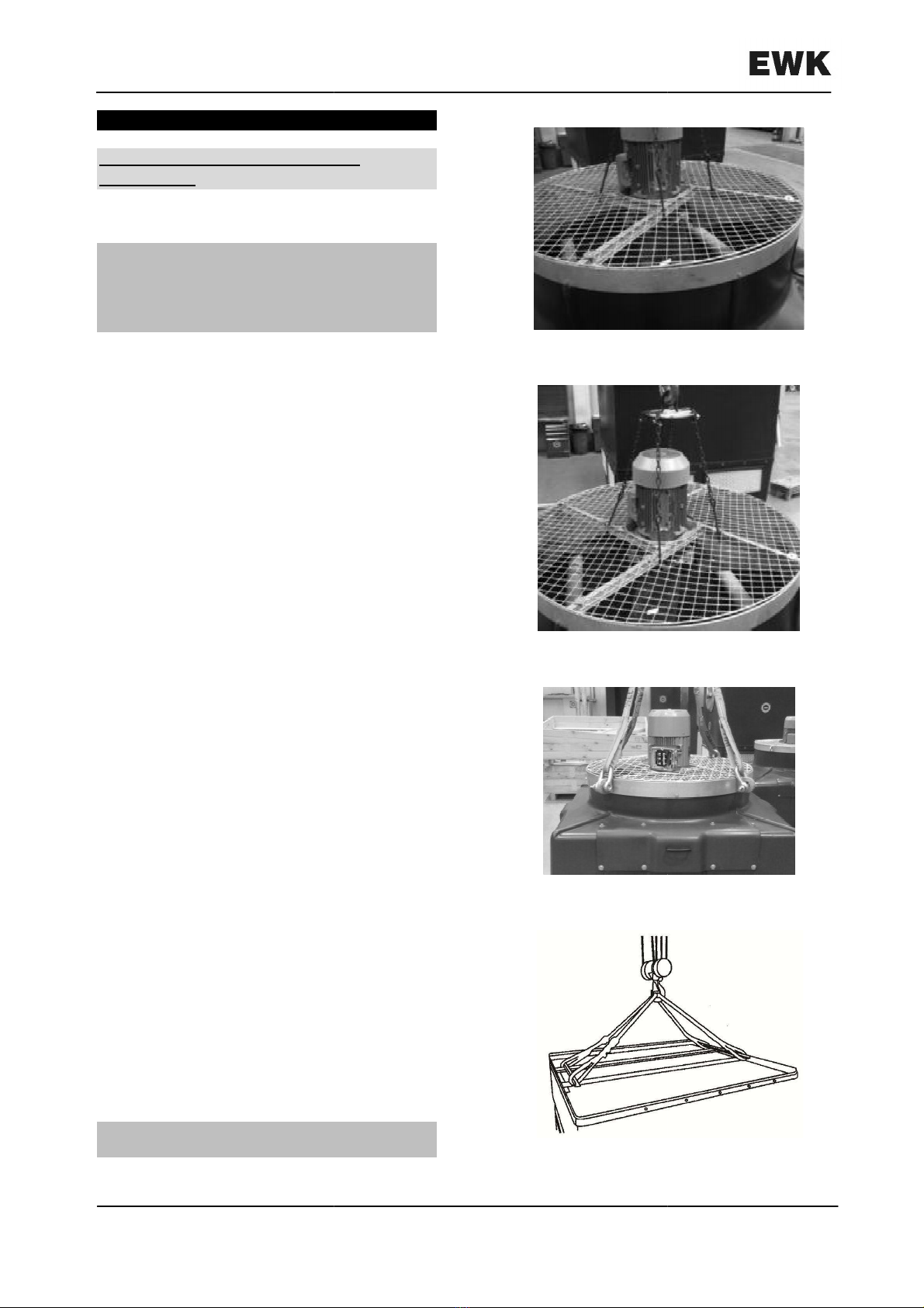
a) Hook the
eye bolts of the fan supporting
ring,
by means of a sling
shown in figure 4.
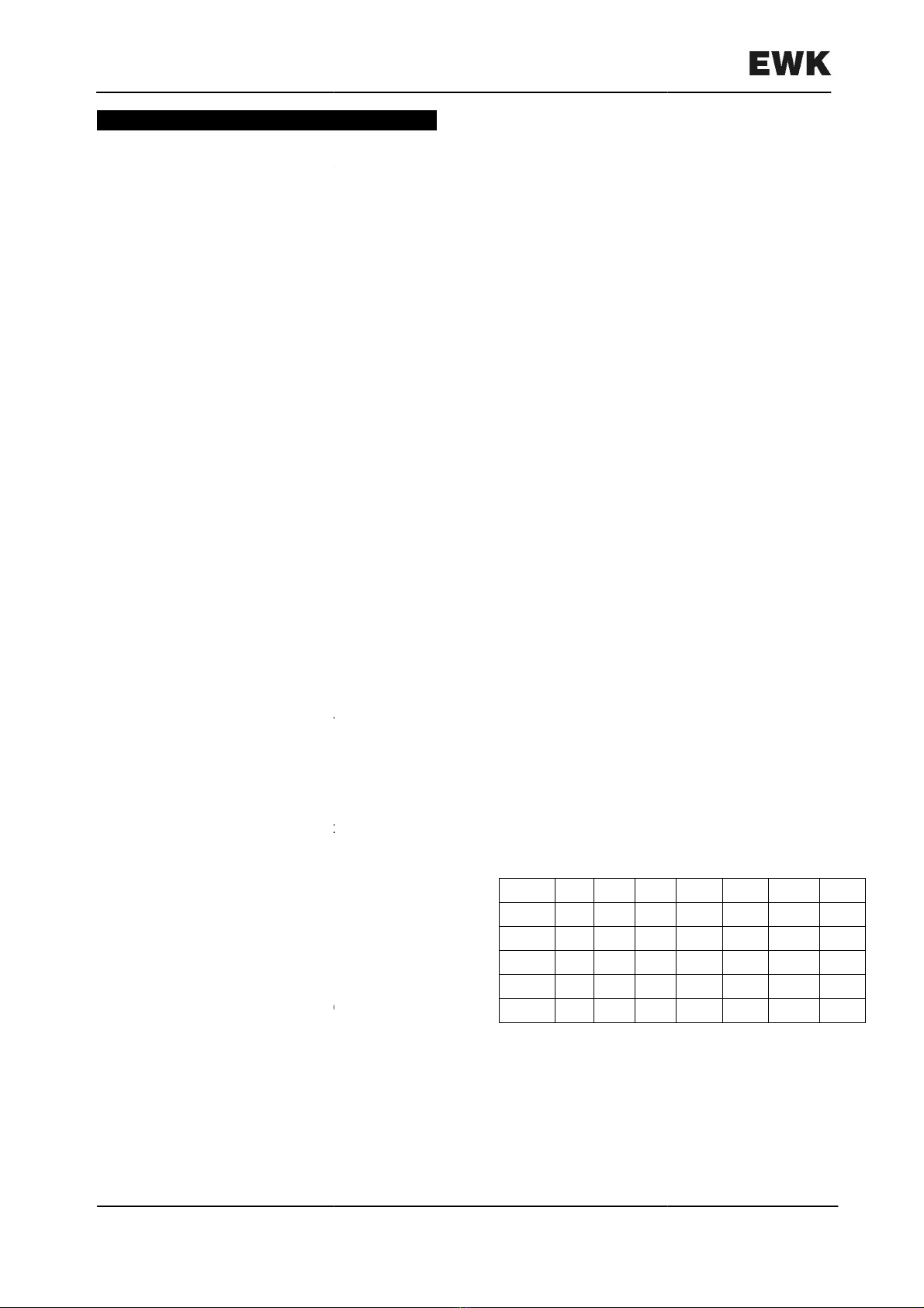
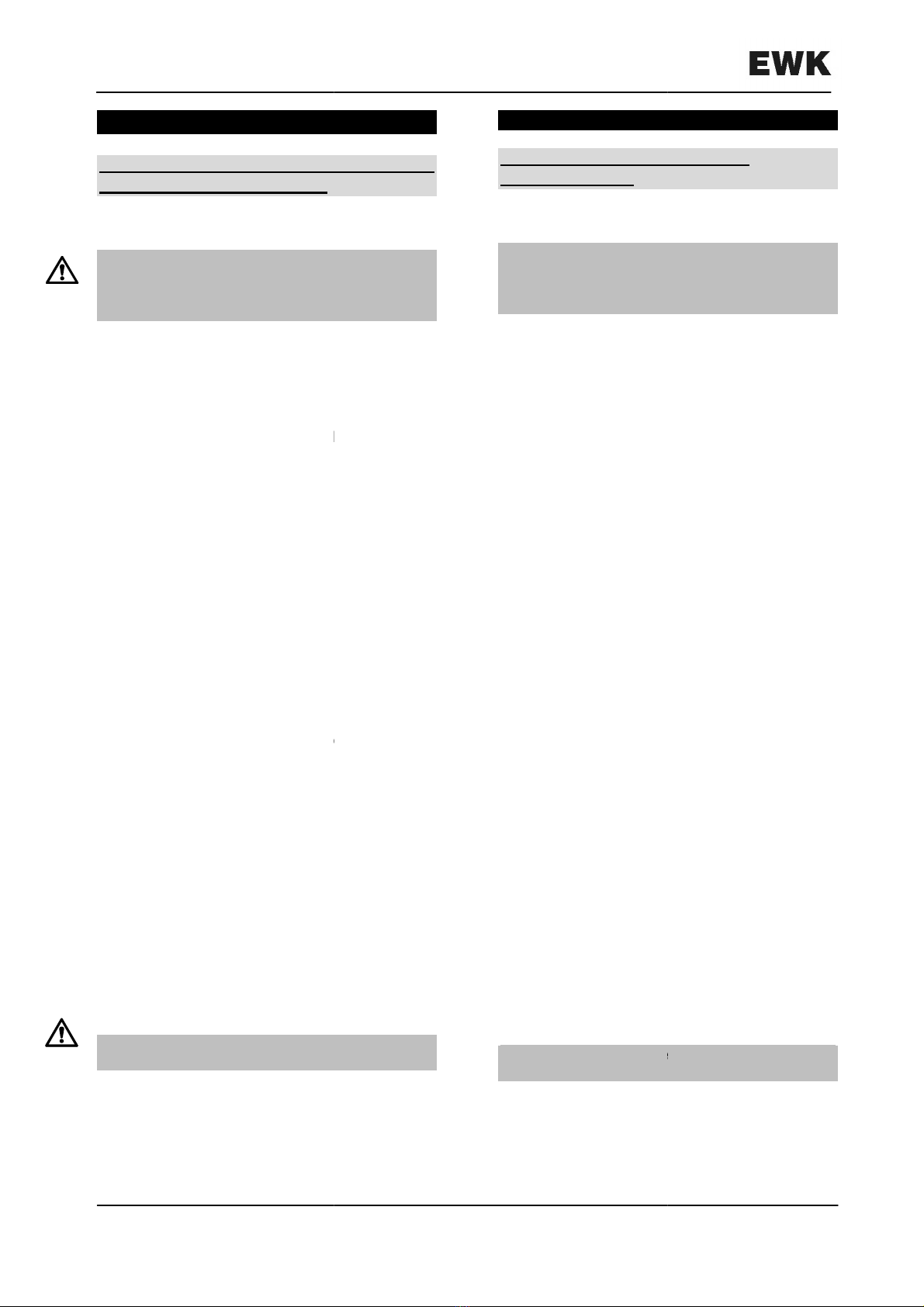
b) Fix some hooks in the spokes of the fan
supporting ring in the way previously
shown (Figures 2 and 3)
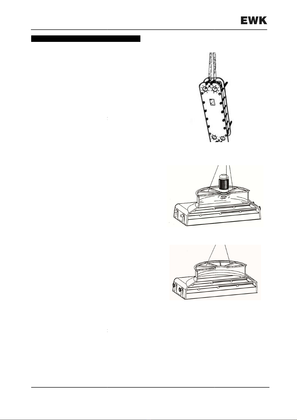
For the handling and unloading of the
collecting basin-
casing assembly, hook a
sling to the special angle device in the way
shown on Figure 5.
WARNING: Once finished the handling
operation
remove the angle device
Englisch
HANDLING, ASSEMBLING AND
WARNING: No cables or chains should be
used for handling and unloading of the
tower components
circuit cooling towers of the EWK
-I
different ways:
I 144/09; EWK
-I 225/09;
I 441/09; EWK
-I 680/09;
on pallets, handling
f a fork lift (fork
I 144: 1.400mm; EWK
-I 225:
I 324: 2.000mm; EWK
-I 441-
900: 2.400mm). For the case that parts are
not delivered on pallets and for further
handling after unloading please
follow the
The first part have basin, middle casing, the
second one have top casing together with
and fan, and the third one have the
the plate heat exchanger.
For the handling and unloading of the upper
methods can be employed:
eye bolts of the fan supporting
by means of a sling
, in the way
b) Fix some hooks in the spokes of the fan
supporting ring in the way previously
For the handling and unloading of the
casing assembly, hook a
sling to the special angle device in the way
WARNING: Once finished the handling
remove the angle device
.
Français–
French
3.-
MANUTENTION, MONTAGE ET
RACCORDEMENT
3.1.-
Manutention de déchargement
ATTENTION: Pour la manutention de
déchargement on ne doit employer ni câbles
ni chaînes, puisqu’ils pourraient abîmer les
composants de la tour.
Les tours de réfrigération de circuit
type EWK-I
peuvent être fournies de
différentes façons:
1)
En trois parties (modèles EWK
EWK-I 225/09; EWK
-
EWK-I 680/09; EWK
-
Lorsque les pièces sont livrées sur des
palettes, la manipulation
moyen d'un chariot élévateur à fourche
(longueur à la fourche
EWK-I
225: 1.700mm; EWK
EWK-I 441-
900: 2.400mm
pièces
ou pour des manipulations suivantes,
suivre les indications ci
La première partie comprend le bassin et
l’enveloppe, la seconde comprend la partie
supérieure et son moto ventilateur, la
troisième comprend l’échangeur et la pompe.
Pour la manipul
ation et décharge du
capuchon on peut employer deux méthodes:
a) Accrocher les
points d’élevage trouvés
dans l’anneau support du ventilateur,
moyen d´une élingue comme il est indiqué
sur la figure 4.
b)
Placer des fourches aux rayons de
l´anneau support du
est indiqué avant (figures 2 et 3).
Pour la manipulation et décharge de
l´ensemble bassin-
carcasse, accrocher une
élingue à l´outil angulaire comme il est
indiqué sur la figure 5.
ATTENTION: Démonter l´outil
fois finie
l´opération de manipulation.
Pag./Seite 12
French
– Französisch
MANUTENTION, MONTAGE ET
Manutention de déchargement
ATTENTION: Pour la manutention de
déchargement on ne doit employer ni câbles
ni chaînes, puisqu’ils pourraient abîmer les
composants de la tour.
Les tours de réfrigération de circuit
fermé
peuvent être fournies de
deux
En trois parties (modèles EWK
-I 144/09;
-
I 324/09; EWK-I 441/09;
-
I 900/09).
Lorsque les pièces sont livrées sur des
palettes, la manipulation
doit être faite au
moyen d'un chariot élévateur à fourche
(longueur à la fourche
: EWK-I 144: 1.400mm;
225: 1.700mm; EWK
-I 324: 2.000mm;
900: 2.400mm
). Pour le reste de
ou pour des manipulations suivantes,
suivre les indications ci
-après:
La première partie comprend le bassin et
l’enveloppe, la seconde comprend la partie
supérieure et son moto ventilateur, la
troisième comprend l’échangeur et la pompe.
ation et décharge du
capuchon on peut employer deux méthodes:
points d’élevage trouvés
dans l’anneau support du ventilateur,
au
moyen d´une élingue comme il est indiqué
Placer des fourches aux rayons de
l´anneau support du
ventilateur comme il
est indiqué avant (figures 2 et 3).
Pour la manipulation et décharge de
carcasse, accrocher une
élingue à l´outil angulaire comme il est
indiqué sur la figure 5.
ATTENTION: Démonter l´outil
angulaire une
l´opération de manipulation.
German– Allemand -
Deutsch
3.-
HANDHABUNG, MONTAGE UND
ANSCHLUSS
3.1.- Handhabung und Entladen
ACHTUNG:
Bei der Handhabung und beim
Ent
laden des Kühlturms dürfen weder Kabel
noch Ketten verwendet werden, da diese die
Komponenten des Kühlturms beschädigen
könnten.
Die Kühltürme mit geschlossenem Kreislauf
aus der Baureihe EWK-
I können in zwei
Versionen geliefert werden:
1) In drei Teilen (Modell EWK-
I 144/09; EWK
225/09; EWK-I 324/09; EWK-
I 441/09; EWK
680/09; EWK-I 900/09
).
Wenn die Bauteile auf Paletten angeliefert
werden, können diese mit einem
Gabelstapler
(Zinkenlänge
1.400mm; EWK-I
225: 1.700mm; EWK
2.000mm; EWK-I 441-
900: 2.400mm
e
ntladen werden. Wenn die Bauteile nicht auf
Paletten angeliefert werden und für die
Handhabung nach dem Entladen, folgende
Anweisungen beachten.
Das erste Teil besteht aus der Baugruppe
Sammler-
Gehäuse, der zweite
Baugruppe Obere Abdeckung
und der dritte aus der Baugruppe
Wärmetauscher-Pumpe.
Für die Handhabung und zum Ausladen der
oberen Abdeckung können die beiden
folgenden Methoden angewendet werden:
a)
Das Anheben kann auch mit Hilfe von
Sch
lingen, die an den Augenschrauben
des Ventilatorrings angebracht werden,
erfolgen (siehe Abb. 4).
b)
Die Hakenvorrichtung an den Speichen
des Sicherungsrings des Ventilators wie
zuvor beschrieben (Abb. 2 und 3)
einhaken.
Für die Handhabung und zum Auslade
Baugruppe Sammler -
Gehäuse wird wie in
Abb. 5 gezeigt ein Seil an den
Befestigungswinkel angelegt.
ACHTUNG:
Den Befestigungswinkel nach
der Handhabung abmontieren.
Deutsch
HANDHABUNG, MONTAGE UND
Bei der Handhabung und beim
laden des Kühlturms dürfen weder Kabel
noch Ketten verwendet werden, da diese die
Komponenten des Kühlturms beschädigen
Die Kühltürme mit geschlossenem Kreislauf
I können in zwei
I 144/09; EWK
-I
I 441/09; EWK
-I
Wenn die Bauteile auf Paletten angeliefert
werden, können diese mit einem
(Zinkenlänge
EWK-I 144:
225: 1.700mm; EWK
-I 324:
900: 2.400mm
)
ntladen werden. Wenn die Bauteile nicht auf
Paletten angeliefert werden und für die
Handhabung nach dem Entladen, folgende
Das erste Teil besteht aus der Baugruppe
Gehäuse, der zweite
aus der
Baugruppe Obere Abdeckung
-Motorgruppe
und der dritte aus der Baugruppe
Für die Handhabung und zum Ausladen der
oberen Abdeckung können die beiden
folgenden Methoden angewendet werden:
Das Anheben kann auch mit Hilfe von
lingen, die an den Augenschrauben
des Ventilatorrings angebracht werden,
Die Hakenvorrichtung an den Speichen
des Sicherungsrings des Ventilators wie
zuvor beschrieben (Abb. 2 und 3)
Für die Handhabung und zum Auslade
n der
Gehäuse wird wie in
Abb. 5 gezeigt ein Seil an den
Den Befestigungswinkel nach
Fig./Abb.
Fig./Abb.
Fig./Abb.
Fig./Abb.
Pag./Seite 13
Fig./Abb.
2
Fig./Abb.
3
Fig./Abb.
4
Fig./Abb.
5

English – Anglais -
Englisch
For the handling and unloading of the
collecting PHE-
pump, hook a sling on the
plate heat
exchanger as show the picture
number 6.
2) In seven parts (EWK-I 1260
/09
1800 models).
The fifth and sixth parts both
have plate heat
exchanger and
collecting and the seventh
the motor.
When parts are delivered on pallets, handling
can be made by means of a fork lift (fork
length 2.400mm). For the case that parts are
not delivered on pallets and for further
handling after unloading please follow the
following instructions
For the handling and unloading of upper
a)
In the part including the electric motor,
hook a sling to two of the spokes of the
fan supporting ring
(or to the eye bolts)
fastening the motor
to balance the
assembly in the way
shown on Figure
b)
In the part not including the electric
hook a sling to two of the spokes
fan supporting ring in the way
Figure 8.
For the handling and unloading of the
collecting basing-
casing assemblies,
procedure
will be similar to the one
for two parts towers (Figure 5).
For the handling and unloading of the
collecting PHE-
pump, hook a sling on the plate
heat exchanger
as show the picture number
Handling and unloading of the silencer (if
fitted).
For the handling and unloading of the
silencer,
hook a sling in the lugs located in the
upper part of silencer as shown in Figure
Englisch
For the handling and unloading of the
pump, hook a sling on the
exchanger as show the picture
/09
and EWK-I
The fifth and sixth parts both
exchanger and
pump
the motor.
When parts are delivered on pallets, handling
can be made by means of a fork lift (fork
length 2.400mm). For the case that parts are
not delivered on pallets and for further
handling after unloading please follow the
For the handling and unloading of upper
cap:
In the part including the electric motor,
hook a sling to two of the spokes of the
(or to the eye bolts)
,
to balance the
shown on Figure
7.
In the part not including the electric
motor,
hook a sling to two of the spokes
of the
fan supporting ring in the way
shown on
For the handling and unloading of the
two
casing assemblies,
the
will be similar to the one
shown
for two parts towers (Figure 5).
For the handling and unloading of the
pump, hook a sling on the plate
as show the picture number
6.
Handling and unloading of the silencer (if
For the handling and unloading of the
hook a sling in the lugs located in the
upper part of silencer as shown in Figure
9.
Français–
French
Pour la manutention et le déchargement de
l’ensemble échangeur /pompe, fixer une
élingue sur l’échangeur comme indiqué sur la
figure 6.
2) En six parties
(modèles EWK
EWK-
I 1800/09). Les cinquièmes et sixièmes
parties comprennent toutes les d
ensemble échangeur/pompe
le moteur.
Lorsque les pièces sont livrées sur des
palettes, la manipulation
moyen d'un chariot élévateur à fourche
(longueur à la fourche
reste de pièces ou pour des manipulations
suivantes, suivre les indications ci
Pour la manipulation et décharge du
capuchon:
a)
Dans la quatrième partie qui porte le
moteur, accrocher une élingue à deux des
rayons
(ou bien aux points d’élevage)
l´anneau support du ventilateur
attacher le moteur pour équilibrer
l´ensemble
comm
figure 7.
b) Dans la quatrième partie qui ne porte pas
le moteur, accrocher une élingue à deux
des rayons de l´anneau support du
ventilateur
comme il est indiqué sur la
figure 8.
Pour la manipulation et décharge de
l´ensemble
bassin
procédera
de la même façon à ce qui est
indiqué
pour la tour en deux parties
(figure 5).
Pour la manutention et le déchargement de
l’ensemble échangeur /pompe, accrocher une
élingue sur l’échangeur de chaleur de la
manière indiquée sur
la figure
Manipulation et décharge du silencieux (s´il
se monte).
Pour la manipulation et décharge du
silencieux, accrocher une élingue sur les
d’élevage
placées dans la partie supérieure du
silencieux comme il est indiqué sur la figure
Pag./Seite 14
French
– Französisch
Pour la manutention et le déchargement de
l’ensemble échangeur /pompe, fixer une
élingue sur l’échangeur comme indiqué sur la
(modèles EWK
-I 1260/09;
I 1800/09). Les cinquièmes et sixièmes
parties comprennent toutes les d
eux un
ensemble échangeur/pompe
, et la septième
Lorsque les pièces sont livrées sur des
palettes, la manipulation
doit être faite au
moyen d'un chariot élévateur à fourche
(longueur à la fourche
: 2.400mm). Pour le
reste de pièces ou pour des manipulations
suivantes, suivre les indications ci
-après:
Pour la manipulation et décharge du
Dans la quatrième partie qui porte le
moteur, accrocher une élingue à deux des
(ou bien aux points d’élevage)
de
l´anneau support du ventilateur
, et
attacher le moteur pour équilibrer
comm
e il est indiqué sur la
b) Dans la quatrième partie qui ne porte pas
le moteur, accrocher une élingue à deux
des rayons de l´anneau support du
comme il est indiqué sur la
Pour la manipulation et décharge de
bassin
-carcasse, on
de la même façon à ce qui est
pour la tour en deux parties
Pour la manutention et le déchargement de
l’ensemble échangeur /pompe, accrocher une
élingue sur l’échangeur de chaleur de la
la figure
6.
Manipulation et décharge du silencieux (s´il
Pour la manipulation et décharge du
silencieux, accrocher une élingue sur les
points
placées dans la partie supérieure du
silencieux comme il est indiqué sur la figure
9.
German– Allemand -
Deutsch
Für die Handhabung und zum Ausladen der
Baugruppe Wärmetauscher -
Pumpe wird wie
in Abb. 6 gezeigt ein Seil an den
Wärmetauscher angelegt.
2)
In sieben Teilen (Modelle EWK
-
EWK-
I 1800/09. Der fünfte und sechste Teil
beinhaltet die Baugruppen Wärmetauscher
und Pumpe.
Der siebte Teil beinhaltet den
Motor
.
Wenn die Bauteile auf Paletten angeliefert
werden, können diese mit einem
Gabelstapler (Zinkenlänge 2.400mm)
entladen werden. Wenn die Bauteile nicht
auf Paletten angeliefert werden und für die
Handhabung nach dem Entladen, folgende
Anweisungen beachten
Für die Handhabung und das Ausladen der
oberen Abdeckung:
a)
In dem vierten Bauteil, das mit dem Motor
ausgerüstet ist, muss an zwei Speichen
des Ventilatorstützrings (oder an den
Augenschrauben
des Ventilatorrings) ein
Seil eingehängt und der Motor befestigt
werden, um diese Baugruppe wie in Abb.
7 aufgeführt zu stabilisieren.
b)
In dem vierten Bauteil, das nicht mit dem
Motor ausgerüstet ist, muss an zwei
Speichen des Ventilatorstützrings ein Seil
befestigt werden (Abb. 8).
Für die Handhabung und das Ausladen
der beiden Baugruppen Sammler
Gehäuse muss wie für die Kühltürme in
zwei Bauteilen (Abb. 5) vorgegangen
werden.
Für die Handhabung und zum Ausladen der
Baugruppe Wärmetauscher -
Pumpe wir
Abb. 6 gezeigt ein Seil an den Wärmetauscher
angelegt.
Handhabung und Entladen des
Schalldämpfers (
optionales Zubehör
Für die Handhabung und das Ausladen des
Auslassschalldämpfers wird wie in Abbildung 9
gezeigt ein Seil an den Lastösen des
Schalldämpferoberteils angelegt.
Deutsch
Für die Handhabung und zum Ausladen der
Pumpe wird wie
in Abb. 6 gezeigt ein Seil an den
-
I 1260/09 und
I 1800/09. Der fünfte und sechste Teil
beinhaltet die Baugruppen Wärmetauscher
Der siebte Teil beinhaltet den
Wenn die Bauteile auf Paletten angeliefert
werden, können diese mit einem
Gabelstapler (Zinkenlänge 2.400mm)
entladen werden. Wenn die Bauteile nicht
auf Paletten angeliefert werden und für die
Handhabung nach dem Entladen, folgende
Für die Handhabung und das Ausladen der
In dem vierten Bauteil, das mit dem Motor
ausgerüstet ist, muss an zwei Speichen
des Ventilatorstützrings (oder an den
des Ventilatorrings) ein
Seil eingehängt und der Motor befestigt
werden, um diese Baugruppe wie in Abb.
7 aufgeführt zu stabilisieren.
In dem vierten Bauteil, das nicht mit dem
Motor ausgerüstet ist, muss an zwei
Speichen des Ventilatorstützrings ein Seil
Für die Handhabung und das Ausladen
der beiden Baugruppen Sammler
-
Gehäuse muss wie für die Kühltürme in
zwei Bauteilen (Abb. 5) vorgegangen
Für die Handhabung und zum Ausladen der
Pumpe wir
d wie in
Abb. 6 gezeigt ein Seil an den Wärmetauscher
Handhabung und Entladen des
optionales Zubehör
):
Für die Handhabung und das Ausladen des
Auslassschalldämpfers wird wie in Abbildung 9
gezeigt ein Seil an den Lastösen des
Fig./Abb.
Fig./Abb.
Fig./Abb.
Pag./Seite 15
Fig./Abb.
6
Fig./Abb.
7
Fig./Abb.
8

Fig./Abb. 9
Pag./Seite 16
English – Anglais -
Englisch
3.2.- Ass
embling and erecting on site
3.2.1.- Assembly of towers
In case the towers arrive not fully assembled,
this assembly will be
made in the following way:
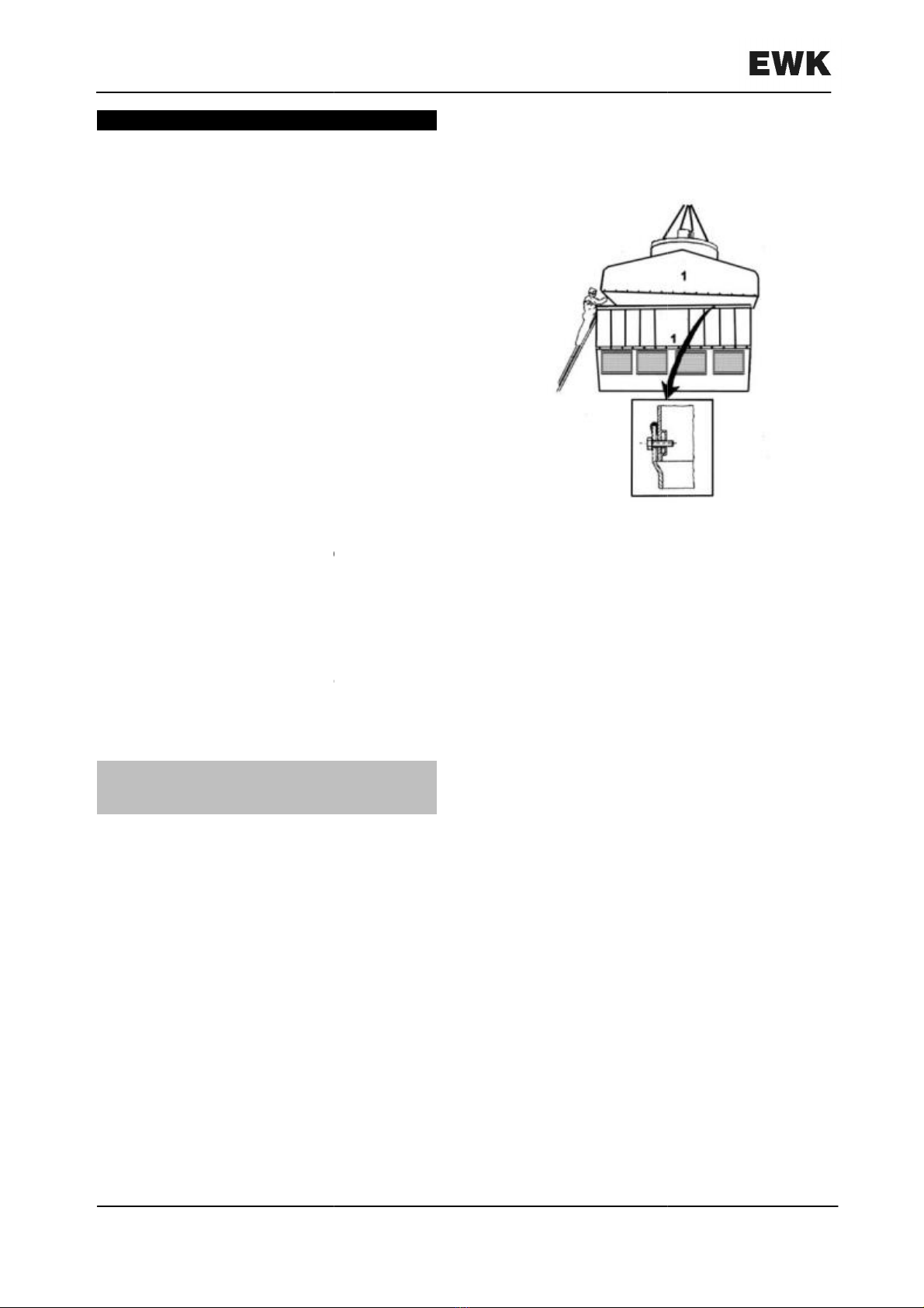
1) Assembly of polyester pieces:
a) Polyester in two pieces
Assembly of upper cap and casing (Figure
10):
1. Remove the rubber seal rolled inside
the tower.
2. Assemble the rubber seal on the
casing.
3.
Place the upper cap on the casing,
making sure that the numbers
appearing in upper cap and casing are
coincident.
4.
Fasten both pieces together
assembling the corresponding screws
and washers, beginning with the
screws in the corners.
b) Polyester in four parts:
WARNING: The assembly of towers in four
parts must be made always under the
supervision of a technician from
Englisch
embling and erecting on site
In case the towers arrive not fully assembled,
made in the following way:
Assembly of upper cap and casing (Figure
1. Remove the rubber seal rolled inside
2. Assemble the rubber seal on the
Place the upper cap on the casing,
making sure that the numbers
appearing in upper cap and casing are
Fasten both pieces together
assembling the corresponding screws
and washers, beginning with the
WARNING: The assembly of towers in four
parts must be made always under the
supervision of a technician from
EWK.
Français–
French
3.2.- Montage et
placement
3.2.1.-
Montage des tours
Dans le cas où les
complètement montées, leur montage sera
réalise de la façon suivante:
1) As
semblage des pièces en polyester:
a) Polyester
en deux parties
Union du capuchon et la carcasse (
10):
1.
Sortir le joint en caoutchouc qui se trouve
rou
lé à l´intérieur de la tour.
2. Monter le joint en caoutchouc sur la
carcasse.
3. Placer le capuchon sur la carcasse en
faisant coïncider les numéros qui
apparaissent dans le capuchon et la
carcasse.
4. Unir les deux parties en plaçant les vis et
les r
ondelles qui correspondent, en
commençant par les vis des coins.
b) Polyester
en quatre parts.
ATTENTION: Le montage des tours en quatre
parts doit toujours être réalisé sous la
supervision d´un technicien de
.
Pag./Seite 17
French
– Französisch
placement
Montage des tours
Dans le cas où les
tours n´arrivent pas
complètement montées, leur montage sera
réalise de la façon suivante:
semblage des pièces en polyester:
en deux parties
Union du capuchon et la carcasse (
Figure
Sortir le joint en caoutchouc qui se trouve
lé à l´intérieur de la tour.
2. Monter le joint en caoutchouc sur la
3. Placer le capuchon sur la carcasse en
faisant coïncider les numéros qui
apparaissent dans le capuchon et la
4. Unir les deux parties en plaçant les vis et
ondelles qui correspondent, en
commençant par les vis des coins.
en quatre parts.
ATTENTION: Le montage des tours en quatre
parts doit toujours être réalisé sous la
supervision d´un technicien de
EWK.
German– Allemand -
Deutsch
3.2.- Montage und Aufstellung
3.2.1.-
Montage der Kühltürme
Sollten die Türme nicht vollständig montiert
gel
iefert werden, wird die Montage
vorgenommen:
1) Zusammenbau der Elemente aus Polyester:
a) Polyester in 2 Teilen
Zusammenbau
der oberen Abdeckung
und des Gehäuses (Abb. 10):
1.
Die Gummidichtung, die im
Innenraum des Turms aufgerollt ist,
herausnehmen.
2.
Die Gummidichtung an das Gehäuse
montieren.
3.
Die Abdeckung auf das Gehäuse
setzen und dafür sorgen, dass die
Nummern der Abdecku
des Gehäuses übereinstimmen.
4.
Beide Module befestigen, indem die
jeweiligen Schrauben und
Unterlegscheiben angelegt werden
(jeweils an den Ecken beginnen).
b) Polyester in vier Teilen.
ACHTUNG:
Kühltürme, die aus vier Modulen
bestehen, müssen immer unter Aufsicht
eines EWK-
Technikers montiert werden.
Deutsch
Montage der Kühltürme
Sollten die Türme nicht vollständig montiert
iefert werden, wird die Montage
wie folgt
1) Zusammenbau der Elemente aus Polyester:
der oberen Abdeckung
Die Gummidichtung, die im
Innenraum des Turms aufgerollt ist,
Die Gummidichtung an das Gehäuse
Die Abdeckung auf das Gehäuse
setzen und dafür sorgen, dass die
Nummern der Abdecku
ng mit denen
des Gehäuses übereinstimmen.
Beide Module befestigen, indem die
jeweiligen Schrauben und
Unterlegscheiben angelegt werden
(jeweils an den Ecken beginnen).
Kühltürme, die aus vier Modulen
bestehen, müssen immer unter Aufsicht
Technikers montiert werden.
Fig./Abb.
Pag./Seite 18
Fig./Abb.
10

English – Anglais -
Englisch
2) Heat exchanger/pump
When the
assembly of tower
casing) is
finished, we assembly
heat exchanger and the pump collecting
together with the cooling tower
.
The assembly will make
as follow:
1.
The previous joint will be placed near
the cooling tower, in the side that
found the inlet distribution pipes.
2. Th
e aspiration pipe will be installed as
picture 11,
connecting the cooling
tower outlet and the pump.
the flange, follow the assembly
instructions steps as show the
picture12.
3.
The driving pipe leave our factory
installed, if not, you have to ins
driving pipe to connect the outlet pump
with the plate heat exchanger, as show
the picture 11.
4.
Finally, you have to install the main
header as show the picture
install the plate heat exchanger outlet
with the cooling tower inlet.
The
pictures are faithful to EWK
EWK-I 144/09 to EWK-I 900/09.
In EWK-I 1260/09 and EWK-
I 1800/09 cases,
assembly the cooling tower we will make the
same, but in this case we will have two plate
heat exchanger and pump collecting instead of
one.
Englisch
assembly of tower
(polyester
finished, we assembly
the plate
heat exchanger and the pump collecting
.
as follow:
The previous joint will be placed near
the cooling tower, in the side that
found the inlet distribution pipes.
e aspiration pipe will be installed as
connecting the cooling
tower outlet and the pump.
To install
the flange, follow the assembly
instructions steps as show the
The driving pipe leave our factory
installed, if not, you have to ins
tall the
driving pipe to connect the outlet pump
with the plate heat exchanger, as show
Finally, you have to install the main
header as show the picture
13, to
install the plate heat exchanger outlet
with the cooling tower inlet.
pictures are faithful to EWK
-I model from
I 1800/09 cases,
to
assembly the cooling tower we will make the
same, but in this case we will have two plate
heat exchanger and pump collecting instead of
Français–
French
2) Echangeur/pompe
Une fois le
montage de la tour
(carcasse en polyester)
l’assemblage de l’ensemble échangeur /
pompe avec la tour.
Le montage s’effectuera de la manière
suivante:
1.
L’ensemble échangeur /pompe sera
positionné du côté de la tour où sont
situés les tubes E/S d’eau.
2.
La tubulure d’aspiration sera montée tel
qu’indiqué sur la figure 1
sortie de la tour à l’aspiration de la
pompe. Le raccordement de la bride du
tube d’aspiration devra être réalisé
selon la figure 1
2
3.
Le tube de refoulement qui relie la sortie
de la pompe à l’entrée de l’échangeur
sera normalement installé
usines, dans le cas contraire il faudra le
monter selon la figure 1
4.
Enfin, il faudra installer le collecteur sur
la partie supérieure de la tour selon les
indications de la figure 1
sortie de l’échangeur de chaleur à
l’entrée de
la tour
Les figures indiquées concernent du modèle
EWK I 144/09 à EWK I 900/09.
Le montage des modèles EWK I 1260/09 et
EWK I 1800-
09 sera réalisé de la même façon
que décrite antérieurement, mais au lieu d’un
ensemble échangeur/pompe, deux ensembles
sont montés par tour.
Pag./Seite 19
French
– Französisch
montage de la tour
soit réalisé
(carcasse en polyester)
, on procédera à
l’assemblage de l’ensemble échangeur /
Le montage s’effectuera de la manière
L’ensemble échangeur /pompe sera
positionné du côté de la tour où sont
situés les tubes E/S d’eau.
La tubulure d’aspiration sera montée tel
qu’indiqué sur la figure 1
1 en reliant la
sortie de la tour à l’aspiration de la
pompe. Le raccordement de la bride du
tube d’aspiration devra être réalisé
2
.
Le tube de refoulement qui relie la sortie
de la pompe à l’entrée de l’échangeur
sera normalement installé
en nos
usines, dans le cas contraire il faudra le
monter selon la figure 1
1.
Enfin, il faudra installer le collecteur sur
la partie supérieure de la tour selon les
indications de la figure 1
3 pour relier la
sortie de l’échangeur de chaleur à
la tour
Les figures indiquées concernent du modèle
EWK I 144/09 à EWK I 900/09.
Le montage des modèles EWK I 1260/09 et
09 sera réalisé de la même façon
que décrite antérieurement, mais au lieu d’un
ensemble échangeur/pompe, deux ensembles
Table of contents
Popular Accessories manuals by other brands


ROSE DISPLAYS
ROSE DISPLAYS COVER instruction sheet

Cumberland
Cumberland C2000829 installation manual

Suncast
Suncast BMDC2200 Assembly instructions

Honeywell
Honeywell Ademco 5800SS1 installation guide

Brinsea Mini II Advance
Brinsea Mini II Advance Mini II Advance manual

BS Bodensteckdosen Systemtechnik
BS Bodensteckdosen Systemtechnik 85 E Series instruction manual