Cumberland C2000829 User manual

PNEG-2348
IR Hopper Sensor
Model:
C2000829
Installation Manual
PNEG-2348
Version: 4.0
Date: 02-14-22

2PNEG-2348 IR Hopper Sensor Installation
All information, illustrations, photos, and specifications in this manual are based on the latest
information available at the time of publication. The right is reserved to make changes at any
time without notice.

Table of Contents
PNEG-2348 IR Hopper Sensor Installation 3
Contents
Chapter 1 Safety .....................................................................................................................................................4
Safety Guidelines ...................................................................................................................................4
Cautionary Symbols Definitions .............................................................................................................5
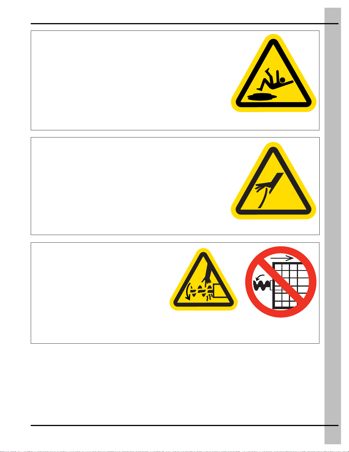
Safety Cautions ......................................................................................................................................6
Safety Sign-Off Sheet ............................................................................................................................8
Chapter 2 Installation ............................................................................................................................................9
Attaching the IR Sensor to the Hopper ..................................................................................................9
Mounting and Wiring the Control Box ..................................................................................................10
IR Plus Feed Sensor Wiring Diagram for Poultry Application ..............................................................11
Flex-Flo Control Unit (FLX-5350) Used with i-Plus3 Control Box (C2000822)
as Hopper Level Controls .....................................................................................................................12
Flex-Flo Control Unit (FLX-5350) Used with IR Plus Feed Sensor (FLX-5262)
as Hopper Level Controls .....................................................................................................................13
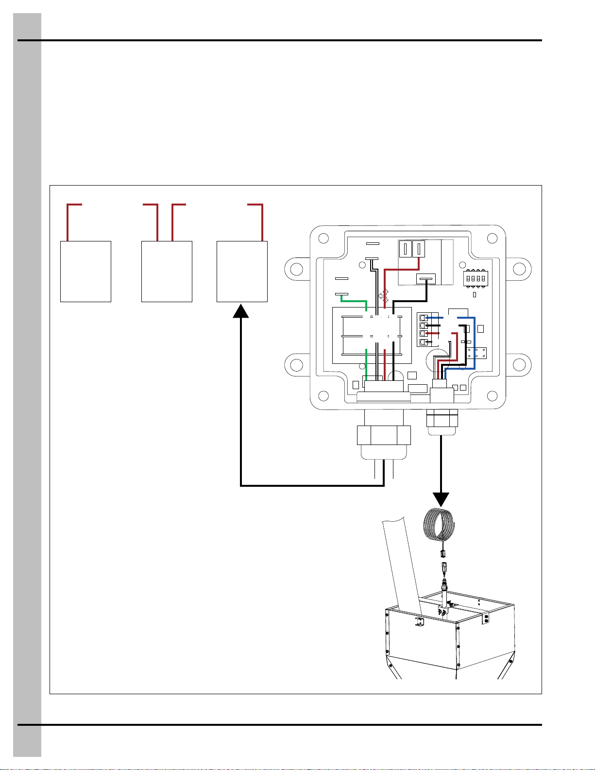
Wiring the IR Hopper Sensor ...............................................................................................................14
Adjusting the IR Hopper Sensor ...........................................................................................................15
Setting the Time Delay .........................................................................................................................15
Chapter 3 Parts List .............................................................................................................................................16
Poultry IR Hopper Sensor with Control (C2000829) Parts ...................................................................16
Chapter 4 Warranty ..............................................................................................................................................17

4PNEG-2348 IR Hopper Sensor Installation
1. Safety
Safety Guidelines
Safety guidelines are general-to-specific safety rules that must be followed at all times. This manual is
written to help you understand safe operating procedures and problems that can be encountered
by the operator and other personnel when using this equipment. Read and save these instructions.
As owner or operator, you are responsible for understanding the requirements, hazards, and precautions
that exist and to inform others as required. Unqualified persons must stay out of the work area at all times.
Alterations must not be made to the equipment. Alterations can produce dangerous situations resulting in
SERIOUS INJURY or DEATH.
This equipment must be installed in accordance with the current installation codes and applicable
regulations, which must be carefully followed in all cases. Authorities having jurisdiction must be consulted
before installations are made.
When necessary, you must consider the installation location relative to electrical, fuel and water utilities.
Personnel operating or working around equipment must read this manual. This manual must be
delivered with equipment to its owner. Failure to read this manual and its safety instructions is a misuse
of the equipment.
ST-0001-4

1. Safety
PNEG-2348 IR Hopper Sensor Installation 5
Cautionary Symbols Definitions
Cautionary symbols appear in this manual and on product decals. The symbols alert the user of potential
safety hazards, prohibited activities and mandatory actions. To help you recognize this information, we
use the symbols that are defined below.
DANGER
WARNING
CAUTION
NOTICE
This symbol indicates an imminently hazardous situation
which, if not avoided, will result in serious injury or death.
This symbol indicates a potentially hazardous situation
which, if not avoided, can result in serious injury or death.
This symbol indicates a potentially hazardous situation which,
if not avoided, can result in minor or moderate injury.
This symbol is used to address practices not related to
personal injury.
This symbol indicates a general hazard.
This symbol indicates a prohibited activity.
This symbol indicates a mandatory action.
ST-0005-2

1. Safety
6PNEG-2348 IR Hopper Sensor Installation
Safety Cautions
Use Personal Protective Equipment
Eye
Protection
Hearing
Protection
Hand
Protection
Head
Protection
Respiratory
Protection
Foot
Protection
Fall
Protection
• Use appropriate personal protective equipment:
• Wear clothing appropriate to the job.
• Remove all jewelry.
• Tie long hair up and back.
ST-0004-1
Follow Safety Instructions
• Carefully read all safety messages in this manual and
safety signs on your machine. Keep signs in good condition.
Replace missing or damaged safety signs. Be sure new
equipment components and repair parts include the current
safety signs. Replacement safety signs are available from
the manufacturer.
• Learn how to operate the machine and how to use controls
properly. Do not let anyone operate without instruction.
• If you do not understand any part of this manual or need
assistance, contact your dealer.
ST-0002-1
Install and Operate Electrical Equipment Properly
• Electrical controls must be installed by a qualified electrician and
must meet the standards set by applicable local codes (National
Electrical Code for the US, Canadian Electric Code, or EN60204
along with applicable European Directives for Europe).
• Lock-out power source before making adjustments, cleaning, or
maintaining equipment.
• Make sure all equipment is properly grounded.
ST-0027-4

1. Safety
PNEG-2348 IR Hopper Sensor Installation 7
Maintain Equipment and Work Area
• Understand service procedures before doing work. Keep area
clean and dry.
• Never service equipment while it is operating. Keep hands, feet
and clothing away from moving parts.
• Keep your equipment in proper working condition. Replace worn
or broken parts immediately.
ST-0003-1
Sharp Edge Hazard
• This product has sharp edges, which can cause serious injury.
• To avoid injury, handle sharp edges with caution and always use
proper protective clothing and equipment.
ST-0036-2
Rotating Auger Hazard
• Keep clear of rotating augers and moving
parts.
• Do not remove or modify guards or
covers.
• Lock-out power source before making
adjustments, cleaning, or maintaining
equipment.
• Failure to follow these precautions will
result in serious injury or death.
ST-0037-1

1. Safety
8PNEG-2348 IR Hopper Sensor Installation
Safety Sign-Off Sheet
Below is a sign-off sheet that can be used to verify that all personnel have read and understood the safety
instructions. This sign-off sheet is provided for your convenience and personal record keeping.
Date Employee Name Supervisor Name
ST-0007

PNEG-2348 IR Hopper Sensor Installation 9
2. Installation
Attaching the IR Sensor to the Hopper
1. Align the IR upper bracket (5) to the two holes in the center strap (20) of the hopper and install using
1/4" x 3/4" HHCS bolts (21) and 1/4" wing nuts (7).
NOTE: Install the HHCS bolt (21) with bolt head under the strap (20).
Figure 2A Attaching the IR Sensor to the Hopper
Ref # Part # Description Ref # Description
5C2000818 IR Upper Bracket 20 Hopper Strap
7S-7002 1/4"-20 Wing Nut 21 1/4"-20 x 3/4" HHCS Bolt (S-6798)
Use only a qualified electrician to perform electrical connections. Follow all
local and national electrical codes.
Disconnect the quick connects before pivoting the hoppers or moving the drop
tubes for cleaning.

2. Installation
10 PNEG-2348 IR Hopper Sensor Installation
Mounting and Wiring the Control Box
The i-Plus3 control box needs to be wired in parallel to the junction box.
1. Mount the (C2000822) i-Plus3 control box to the ceiling near the junction box.
2. Supply 240V AC earth/ground (green), neutral L2 (white) and 240V L1 (black) to the correct leads.
3. Wire the signal wire sensor N.O. (red) in parallel with the other drop tube units to the control unit
(FLX-5350). This will close the loop and provide the control unit with a signal when any of the hoppers
calls for feed.
Figure 2B Wiring the i-Plus3 Control Box
To Junction Box
To IR Hopper Sensor
Junction
Box
i-PLUS3 CONTROL BOX (C2000822)
BLACK
Sensor NO (Red)
Sensor NO (Red)
FLX-5350 Junction
Box
EARTH (Green)
L2 (White)
Sensor NO (Red)
WHITE
RED
BLUE
L1 (Black)
1
ON
234

2. Installation
PNEG-2348 IR Hopper Sensor Installation 11
IR Plus Feed Sensor Wiring Diagram for Poultry Application
Figure 2C
L1 (Black)
NO (Red)
GND (Green)
L2 (White)
L1 (Black)
NO (Red)
GND (Green)
L2 (White)
1
ON
234 1
ON
234
WIRING DIAGRAM FOR FLEX-FLO CONTROL (FLX-4512) TO i-PLUS3 CONTROL BOX (C2000822)
USED AS HOPPER LEVEL CONTROLS FOR POULTRY APPLICATION
i-PLUS3 CONTROL BOX (C2000822)
FEED SENSOR FOR HOPPER #2
i-PLUS3 CONTROL BOX (C2000822)
FEED SENSOR FOR HOPPER #1
RED
BLACK
GREEN
WHITE
L1
GND
L2
230 VAC
POWER
SUPPLY
RED
BLACK
GREEN
WHITE
L1
GND
L2
230 VAC
POWER
SUPPLY
FLEX-FLO
MOTOR
GND
L1 M1 M2 L2
FLEX-FLO CONTROL UNIT
(FLX-4512)

2. Installation
12 PNEG-2348 IR Hopper Sensor Installation
Flex-Flo Control Unit (FLX-5350) Used with i-Plus3 Control Box
(C2000822) as Hopper Level Controls
Figure 2D
L1 (Black)
NO (Red)
GND
(Green)
L2
(White)
L1 (Black)
NO (Red)
GND
(Green)
L2
(White)
1
ON
234
1
ON
234
FLEX-FLO CONTROL UNIT (FLX-5350)
i-PLUS3 CONTROL BOX (C2000822)
FEED SENSOR FOR HOPPER #2
i-PLUS3 CONTROL BOX (C2000822)
FEED SENSOR FOR HOPPER #1
FLEX-FLO
MOTOR
GND 208-230 VAC
POWER SUPPLY
L2
L1
BLACK
WHITE
GREEN
Incoming Power
L1
L2
M1
M2
Power L1
Power L2
COM.
N.O.
Signal IN
Signal Out
M3
Flex-Flo Motor Auxillary Switch
Relay
Output
BLACK
WHITE
GREEN
RED
GREEN
WHITE
BLACK

2. Installation
PNEG-2348 IR Hopper Sensor Installation 13
Flex-Flo Control Unit (FLX-5350) Used with IR Plus Feed Sensor
(FLX-5262) as Hopper Level Controls
Figure 2E
L1 (Black)
L1 (Black)
NO (Red)
NO (Red)
GND
(Green)
GND
(Green)
L2
(White)
L2
(White)
1
ON
234
FLEX-FLO CONTROL UNIT (FLX-5350)
i-PLUS3 CONTROL BOX (C2000822)
FEED SENSOR FOR HOPPER #2
FLEX-FLO
MOTOR
GND 208-230 VAC
POWER SUPPLY
L2
L1
BLACK
WHITE
GREEN
Incoming Power
L1
L2
M1
M2
Power L1
Power L2
COM.
N.O.
Signal IN
Signal Out
M3
Flex-Flo Motor Auxillary Switch
Relay
Output
BLACK
WHITE
GREEN
RED
GREEN
YELLOW
WHITE
BLACK
IR PLUS FEED SENSOR (FLX-5262)
FOR HOPPER #1
NCNO
COM
IR PLUS FEED SENSOR
WITH LID REMOVED
EARTH LINE 2 LINE 1
GND
Power
LED
Auger
LED
Detect
LED
White
Green
Black
Yellow
Yellow
Red
Red
Delay Time
SEL
Off - Sec
On - Min
30
1234
60
90

2. Installation
14 PNEG-2348 IR Hopper Sensor Installation
Wiring the IR Hopper Sensor
Wire the included 10' sensor cable (13) with quick connect into the i-Plus3 control box.
1. Cut the cable to length as needed and connect the loose end to screw terminals inside the
control box.
2. Route the sensor cable (13) down the drop tube and fasten using cable ties.
3. Connect the cable to the IR hopper sensor (19) using the 4-pin quick connect.
Figure 2F Wiring the IR Hopper Sensor
Ref # Description
13 10' Sensor Cable (C2000827)
18 Hopper
19 Sensor

2. Installation
PNEG-2348 IR Hopper Sensor Installation 15
Adjusting the IR Hopper Sensor
1. Initial hoppers needs to adjust sensors towards the top of the hopper to utilize its full capacity, while
still having enough space for feed to flow into the sensor.
2. The last hopper in the row needs to have the sensor placed as low as possible, using the
following criteria:
a. Once the hopper sensor shuts off the over-head line, there needs to be enough feed in the hopper
to sustain the pan feeding line during the one minute built in delay. Use trial and error to place
the hopper sensor at the lowest height possible while also making sure the pan feeding line never
runs empty during this period.
3. Observe the system to ensure the following:
a. The last line doesn’t have the sensor too low so that the out going auger runs empty.
b. The middle hopper drop tube is secured such that the feed will not flow into the sensor.
c. The same criteria will apply when the feed line is raised.
d. All electrical connections are water-tight.
Setting the Time Delay
NOTE: The time delay default is set to 30 seconds at the factory.
1. Select the time delay units by turning dip switch 1 to ON for minutes and OFF for seconds. Turn ON
dip switches 2, 3 and 4 to choose that time delay interval or to add it to the total time delay.
2. All selections add to the time delay total. The maximum amount of time delay in seconds is
180 seconds and the maximum amount of time delay in minutes is 180 minutes.
3. If no time is selected (dip switches 2-4 set to OFF), the default time delay is 10 seconds.
4. On a power cycle, the first time delay will be 10 seconds no matter what time delay is set.
a. Dip Switch #1 selects units: ON = Minutes / OFF = Seconds
b. Dip Switch #2: 30
c. Dip Switch #3: 60
d. Dip Switch #4: 90

16 PNEG-2348 IR Hopper Sensor Installation
3. Parts List
Poultry IR Hopper Sensor with Control (C2000829) Parts
Poultry IR Hopper Sensor with Control (C2000829) Parts List
Ref # Part # Description Qty
C2000819 Poultry IR Hopper Sensor 1
1C2000858 IR Sensor Mount 1
2C2000552 Control Pan Drop Tube 1
3C2000849 IR Hopper Sensor Harness Assembly 1
4C2000814 Nipple, 1/2" x 18" SCH 40 Galvanized 1
5C2000818 IR Upper Bracket 1
6S-10772 Bolt, U-Bolt 1/4"-20 x 7/8" IW x 1-1/2" 1
7S-7002 Nut, Wing 1/4"-20 SS 2
8FH-1309 Nut, Lock 1/2" with Pipe Threads 2
91001-2597 Nut, Lock 8-32 KEP Hex Z 3
10 S-10209 Threaded Stud, #8-32 x 2", Zinc Plated 3
11 VF3-1212 Plug, 4-Pin, Deutsch Style Connector 1
12 VF3-1213 Wedge Lock, 4-Pin, Deutsch Style Connector, Plug 1
13 C2000827 IR Hopper Sensor Cable 10' with 4-Pin Connector 1
14 1003-1461 Washer, Flat 1/4" USS Zinc 2
15 C2000815 Reducer, 1/2" to 1/4" SCH 40 Galvanized 1
16 VF3-1015 Watertight Cordgrip, M3207, Nut Included 1
17 C2000822 IR Hopper i-Plus3 Control Box (220V, 1 PH) 1
N/S BX-173 Box, 6" x 6" x 27-1/4" 200 C RSC C for BFT Ground Control 1
N/S PNEG-2348 Manual, IR Hopper Installation and Operation 1

PNEG-2348 IR Hopper Sensor Installation 17
4. Warranty
Limited Warranty - Protein Products
The GSI Group, LLC. (“GSI”) warrants products which it manufactures, to be free of defects in materials and workmanship
under normal usage and conditions for a period of 12 months from the date of purchase (or, if shipped by vessel, 14 months
from the date of arrival at the port of discharge). If, in GSI’s sole judgment, a product is found to have a defect in materials
and/or workmanship, GSI will, at its own option and expense, repair or replace the product or refund the purchase price.
This Limited Warranty is subject to extension and other terms as set forth below.
Warranty Enhancements:
The warranty period for the following products is enhanced as shown below and is in lieu of (and not in addition to) the
above stated warranty period.
Conditions and Limitations:
THERE ARE NO WARRANTIES THAT EXTEND BEYOND THE LIMITED WARRANTY DESCRIPTION SET FORTH
HEREIN; SPECIFICALLY, GSI DISCLAIMS ANY AND ALL OTHER WARRANTIES OF ANY KIND, EXPRESS OR
IMPLIED, INCLUDING, WITHOUT LIMITATION, WARRANTIES OF MERCHANTABILITY OR FITNESS FOR A
PARTICULAR PURPOSE OR USE IN CONNECTION WITH: (I) ANY PRODUCT MANUFACTURED OR SOLD BY
GSI, OR (II) ANY ADVICE, INSTRUCTION, RECOMMENDATION OR SUGGESTION PROVIDED BY AN AGENT,
REPRESENTATIVE OR EMPLOYEE OF GSI REGARDING OR RELATED TO THE CONFIGURATION, INSTALLATION,
LAYOUT, SUITABILITY FOR A PARTICULAR PURPOSE, OR DESIGN OF SUCH PRODUCTS.
The sole and exclusive remedy for any claimant is set forth in this Limited Warranty and shall not exceed the amount paid
for the product purchased. This Warranty only covers the value of the warranted parts and equipment, and does not cover
labor charges for removing or installing defective parts, shipping charges with respect to such parts, any applicable sales
or other taxes, or any other charges or expenses not specified in this Warranty. GSI shall not be liable for any other direct,
indirect, incidental or consequential damages, including, without limitation, loss of anticipated profits or benefits. Expenses
incurred by or on behalf of a claimant without prior written authorization from the GSI warranty department shall not be
reimbursed. This warranty is not transferable and applies only to the original end user. GSI shall have no obligation
or responsibility for any representations or warranties made by or on behalf of any dealer, agent or distributor. Prior to
installation, the end user bears all responsibility to comply with federal, state and local codes which apply to the location
and installation of the products.
This Limited Warranty extends solely to products sold by GSI and does not cover any parts, components or materials used
in conjunction with the product, that are not sold by GSI. GSI assumes no responsibility for claims resulting from
construction defects, unauthorized modifications, corrosion or other cosmetic issues caused by storage, application or
environmental conditions. Modifications to products not specifically delineated in the manual accompanying the product at
initial sale will void all warranties. This Limited Warranty shall not extend to products or parts which have been damaged
by negligent use, misuse, alteration, accident or which have been improperly/inadequately maintained.
Service Parts:
GSI warrants, subject to all other conditions described in this Warranty, Service Parts which it manufactures for a period
of 12 months from the date of purchase, unless specified in Enhancements above. Parts not manufactured by GSI will carry
the Manufacturer’s Warranty.
Product Warranty Period
AP® Fans Performer Series Direct Drive Fan Motor 3 Years * Warranty prorated from material list price:
0 to 3 years - no material cost to end user
3 to 5 years - end user pays 25%
5 to 7 years - end user pays 50%
7 to 10 years - end user pays 75%
** Warranty prorated from material list price:
0 to 3 years - no material cost to end user
3 to 5 years - end user pays 75%
AP® and Cumberland®Flex-Flo/Pan Feeding System Motors 2 Years
Electronic Controls All Protein controls manufactured by GSI 24 Months from date
code on part
Cumberland®
Feeding and Watering
Systems
Feeder System Pan Assemblies 5 Years, Prorated **
Feed Tubes (1.75" and 2.00") 10 Years, Prorated *
Centerless Augers 10 Years, Prorated *
Watering Nipples 10 Years, Prorated *
(Protein Limited Warranty_REV01_06 November 2018)

Copyright © 2022 by The GSI Group, LLC
Printed in the USA
This equipment shall be installed in accordance with
the current installation codes and applicable
regulations, which should be carefully followed in all
cases. Authorities having jurisdiction should be
consulted before installations are made.
1004 E. Illinois St.
Assumption, IL 62510-0020
Phone: 1-217-226-4421
Fax: 1-217-226-4420
www.cumberlandpoultry.com
CN-402248
Table of contents
Other Cumberland Accessories manuals