EWM HIGHTEC WELDING PHOENIX R10 User manual
EWM
HIGHTEC WELDING GmbH
Dr. Günter-Henle-Straße 8 • D-56271 Mündersbach
Fon +49 2680 181-0 • Fax +49 2680 181-244
www.ewm.de • info@ewm.de
GB
Operating instructions
Remote control
PHOENIX R10
PHOENIX R20
PHOENIX R40
N. B. These operating instructions must be read before commissioning.
Failure to do so may be dangerous.
Machines may only be operated by personnel who are familiar with the appropriate safety
regulations.
The machines bear the conformity mark and thus comply with the
• EC Low Voltage Directive (2006/95/ EG)
• EC EMC Directive (2004/108/ EG)
In compliance with IEC 60974, EN 60974, VDE 0544 the machines can be used in environments
with an increased electrical hazard.
©The content of the operating instructions does not constitute grounds for any claims on the part
of the buyer.
The copyright to these operating instructions remains with the manufacturer.
Reprinting, including extracts, only with written approval.
© 2008 Subject to alteration. Item No.: 099-008088-EWM01 Revised: 04.11.2008
Dear customer,
Congratulations! You have chosen a quality product from EWM HIGHTEC WELDING GmbH.
EWM machines provide results of the highest perfection thanks to their PREMIUM quality. Therefore
we are happy to provide you with a full 3-year warranty according to our operating instructions.
We develop and produce quality! From individual components to the final product, we retain sole
responsibility for our machines.
In all their high-tech components, our welding machines embody future-oriented advanced technology
at the utmost level of quality. Each of our products is carefully checked; we guarantee that the material
and processing of our products is faultless.
These operating instructions contain everything about commissioning the machine, notes regarding
safety, maintenance and care, technical data as well as information regarding the warranty. Please
heed all these notes to ensure many years of safe operation of the machine.
Thank you for the trust that you have placed in us. We look forward to a long-term partnership with you
in the spirit of “ONCE EWM – ALWAYS EWM”.
Yours sincerely,
EWM HIGHTEC WELDING GmbH
Bernd Szczesny
Executive management

Machine and Company Data
Please enter the EWM machine data and your company’s data in the appropriate fields.
CE
EWM HIGHTEC WELDING GMBH
D-56271 MÜNDERSBACH
TYP:
ART:
SNR:
PROJ:
GEPRÜFT/CONTROL:
Name of Customer / company
Adress
Post code / Place
Country
Stamp / Signature of EWM-distibutor
Date of purchase
Name of Customer / company
Adress
Post code / Place
Country
Stamp / Signature of EWM-distibutor
Date of purchase
3

Contents
For your safety
4 Item No.: 099-008088-EWM01
1Contents
1Contents..................................................................................................................................................4
2Safety instructions.................................................................................................................................6
2.1 For your safety...............................................................................................................................6
2.2 Notes on the use of these operating instructions...........................................................................6
3Technical data.........................................................................................................................................7
3.1 PHOENIX R10, R20, R40..............................................................................................................7
4Machine description...............................................................................................................................8
4.1 General...........................................................................................................................................8
4.2 PHOENIX R10, R20, R40..............................................................................................................8
5Functional characteristics...................................................................................................................10
5.1 Basic functions.............................................................................................................................10
5.1.1 MIG/MAG operating point.............................................................................................10
5.2 Advanced functions......................................................................................................................11
5.2.1 Manual remote control R20 ..........................................................................................11
5.2.1.1 Program changeover.....................................................................................11
5.2.2 R40 manual remote control ..........................................................................................11
5.2.2.1 Program changeover.....................................................................................11
5.2.2.2 Program limit.................................................................................................11
5.2.2.3 Specify program down parameter.................................................................12
5.2.2.4 Changing over between standard MIG welding and pulse arc MIG
welding ...............................................................................................................13
5.2.2.5 Operating point setting changeover via wire feed speed or panel
thickness.............................................................................................................13
5.3 Switching on and system diagnosis.............................................................................................13
5.3.1 R40 manual remote control ..........................................................................................13
6Commissioning.....................................................................................................................................14
6.1 Proper usage................................................................................................................................14
6.1.1 For operation only with the following equipment..........................................................14
6.2 Establishing the connections .......................................................................................................14
7Maintenance and testing .....................................................................................................................16
7.1 General.........................................................................................................................................16
7.2 Cleaning.......................................................................................................................................16
7.3 Maintenance.................................................................................................................................16
7.4 Disposing of equipment................................................................................................................16
7.4.1 Manufacturer's declaration to the end user..................................................................16
8Warranty................................................................................................................................................17
8.1 General Validity............................................................................................................................17
8.2 Warranty Declaration ...................................................................................................................18
9Accessories, options ...........................................................................................................................19
9.1 Connection and extension cables................................................................................................19
10 Circuit diagrams...................................................................................................................................20
10.1 PHOENIX R10 .............................................................................................................................20
10.2 PHOENIX R20 .............................................................................................................................21
10.3 PHOENIX R40 .............................................................................................................................22

Contents
For your safety
Item No.: 099-008088-EWM01 5

Safety instructions
For your safety
6 Item No.: 099-008088-EWM01
2Safety instructions
2.1 For your safety
Observe accident prevention regulations!
Ignoring the following safety procedures can be fatal!
Proper usage
This machine has been manufactured according to the latest developments in technology and
current regulations and standards. It is to be operated only for the use for which it was designed
(see chapter Commissioning/Area of application).
Improper usage
However, this machine may be a hazard to persons, animals and property if it is
• not used as directed
• used by unskilled persons who have not been trained
• modified or converted improperly
2.2 Notes on the use of these operating instructions
These operating instructions are arranged into chapters.
To help you find your way around more quickly, in the margins you will occasionally see symbols along
with the sub-headings. These symbols refer to particularly important passages of text which are graded
as follows depending on their importance:
Please note:
Technical features which users must observe.
Warning:
Working and operating procedures which must be followed precisely to avoid damaging or
destroying the machine.
Caution:
Working and operating procedures which must be followed precisely to avoid risk to persons and
includes the "Warning" symbol.
Instructions and lists detailing step-by-step actions in given situations can be recognised by bullet points,
e.g.:
• Insert the welding current lead socket into the relevant socket and lock.
Symbol Description
Press
Do not press
Turn
Switch

Technical data
PHOENIX R10, R20, R40
Item No.: 099-008088-EWM01 7
3Technical data
3.1 PHOENIX R10, R20, R40
Type R10 R20 R40
Port 19-pole, analogue 19-pole, analogue 7-pole, digital
Display - Single-digit 16-digit
Dimensions L x W x H in
mm 180 x 100 x 75 330 x 180 x 95 270 x 150 x 75
Weight in kg 0.86 2.3 1.4

Machine description
General
8 Item No.: 099-008088-EWM01
4Machine description
4.1 General
The remote controls are designed specifically for use with welding machines in the PHOENIX range and
offer various setting options, depending on the model.
Common features:
• Setting the operating point via the wire speed (single-dial operation)
• Arc length correction
PHOENIX R20:
• Changeover and display of up to ten welding programs.
PHOENIX R40:
• Change over, display, create or change up to 16 welding programs.
• Switch superpulse function on or off.
• Change over between standard MIG welding and pulse arc MIG welding
(if supported by the welding machine).
4.2 PHOENIX R10, R20, R40
6
7
4
3
2
1
5
15
1011
12
13
14
9
8
Figure 4-1
Machine description
PHOENIX R10, R20, R40
Item No.: 099-008088-EWM01 9
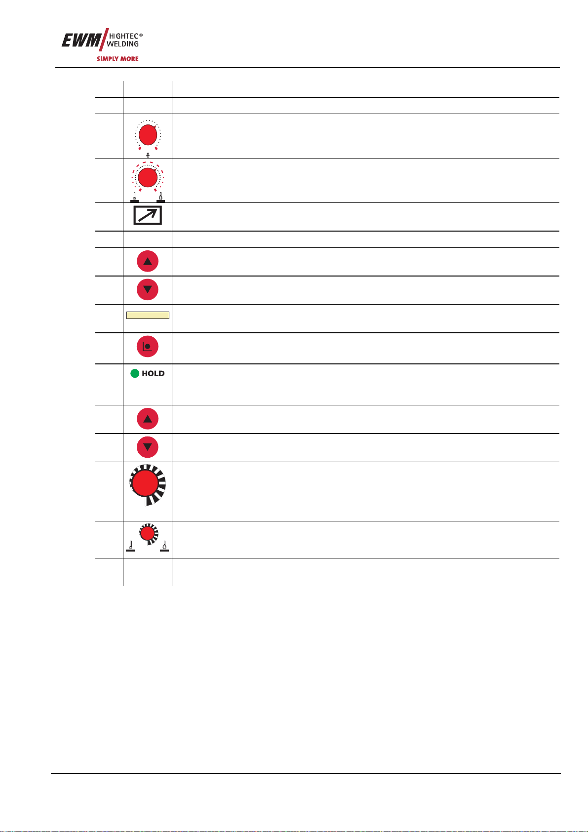
Item Symbol Description 0
1Holder for suspending the remote control
2
0,5
1
1,5
2
2,5
3
3,5
456
7
891011
12
13
14
15
16
18
20
m/min
Wire speed rotary dial
Infinitely adjustable setting of the wire speed from min. to max.
(welding output, one-dial operation)
3
01
1
22
33
77
55
10
10
- V +
“Arc length correction” rotary dial
Arc length correction from -10 V to + 10 V
4 19-pole connection socket (analogue)
For connecting the control lead.
5 Displays the current program number
6 Key button, program switching "Up"
Select program number up
7 Key button, program switching "Down"
Select program number down
8
500A 49,9V
Display, 16-digit
Display of all welding parameters and their values
9 Key button, "Mode"
To select the program runtime parameters
10 Signal light, "HOLD"
Lit: Display shows the last parameters used for welding.
Not lit: Display shows the setpoint values or current values during welding.
11 Key button, program switching "Up"
Select program number up
12 Key button, program switching "Down"
Select program number down
13
m/min
Rotary dial, wire speed
• Setting the wire speed
(0.5 m/min to 24 m/min in 0.1 m/min increments)
• Setting welding parameters
14
- V +
Rotary dial, arc length correction
• -9.9 V to +9.9 V in increments of 0.15 V
15 Connection socket, 7-pole (digital)
Connection to the digital remote control connection on power source or wire feed unit.

Functional characteristics
Basic functions
10 Item No.: 099-008088-EWM01
5Functional characteristics
5.1 Basic functions
5.1.1 MIG/MAG operating point
Operating point setting according to the MIG/MAG single-dial operating principle:
• One of the parameters wire speed, welding current or material thickness is set.
• The control calculates the optimum values for the remaining parameters
The wire speed is generally used to set the operating point.
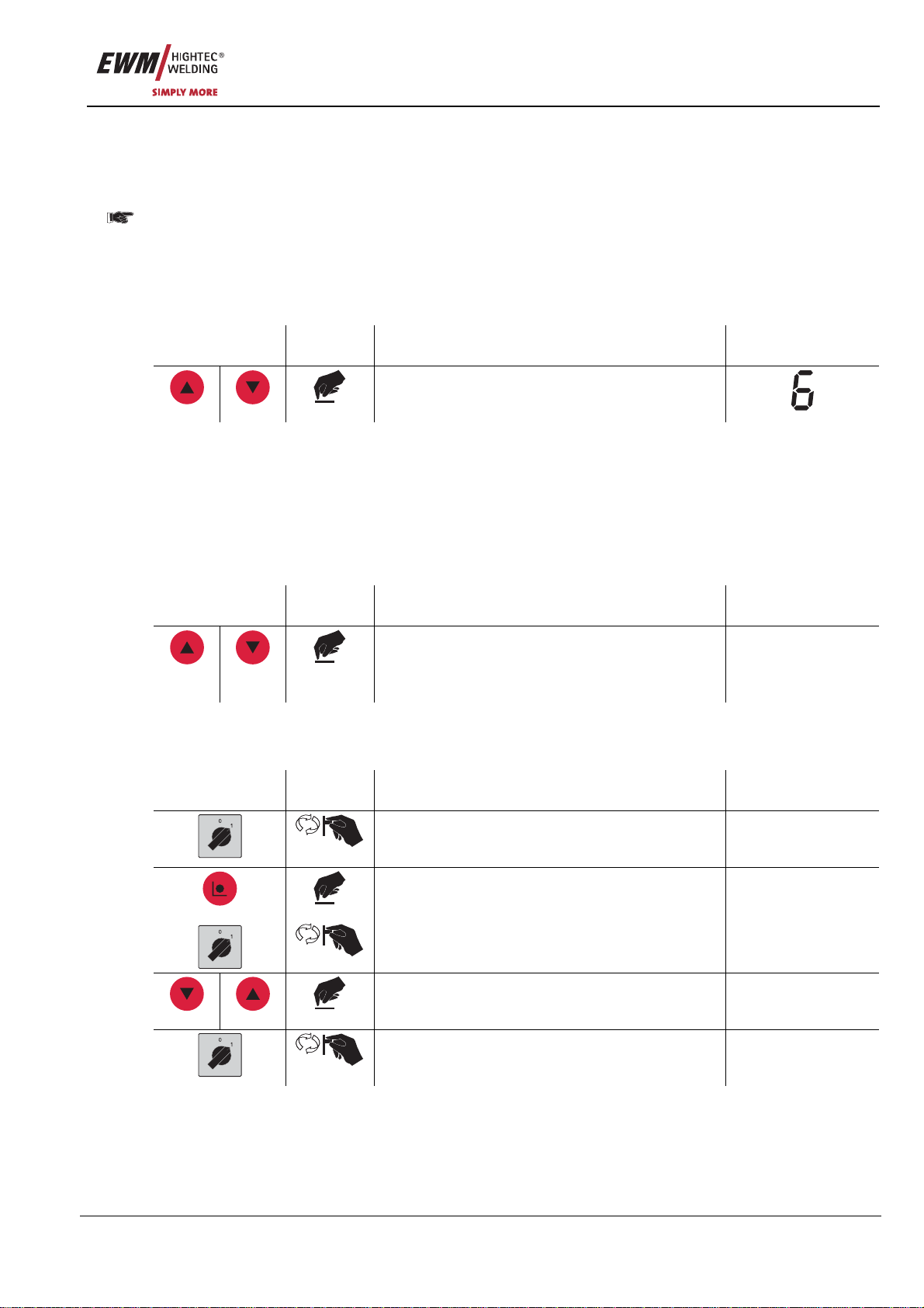
In the situations given below, the wire speed is given to represent the operating point.
Operating
element Action Result Display (R40)
R10
R20
m/min
R40
Operating point setting via wire speed.
Display example: Wire speed 7.6 m/min
(Display for PHOENIX R40 only)
P0 : 7.6M +1.1V
The arc length can be corrected as follows.
Operating
element Action Result Display (R40)
01
1
22
33
77
55
10
10
- V +
R10
R20
- V +
R40
Arc length correction
Display example: Increase by 1.1 V
(Display for PHOENIX R40 only)
P0 : 7.6M +1.1V
Functional characteristics
Advanced functions
Item No.: 099-008088-EWM01 11
5.2 Advanced functions
5.2.1 Manual remote control R20
5.2.1.1 Program changeover
Set "Program or up/down mode" changeover switch on the welding machine or wire feed unit to
the "Up/down mode" position!
• Change between up to ten (0 to 9) welding programs.
• Welding programs are created using the control on the welding machine or wire feed unit. (see
operating instructions for the relevant machine, chapter "Main program mode A")
Operating
element Action Result Display
Select next or previous welding program.
5.2.2 R40 manual remote control
5.2.2.1 Program changeover
• Change between up to 16 (0 to 15) welding programs.
• Welding programs can be created using the control on the welding machine or wire feed unit or using
the remote control itself. (see operating instructions for the relevant machine, chapter "Main program
mode A", or the chapters following these instructions)
Operating
element Action Result Display
Select next or previous welding program. P0 : 7.6M +1.1V
...
P0 : 7.6M +1.1V
5.2.2.2 Program limit
• The maximum number of retrievable welding programs can be limited.
Operating
element Action Result Display
Switch off the welding machine.
+
+
Hold down "Mode" button on the remote control,
switching on the welding machine. PROGRAMME: 0XX
Set program number. PROGRAMME: 0XX
Switch off the welding machine and restart in
order to put the change into effect.
Functional characteristics
Advanced functions
12 Item No.: 099-008088-EWM01
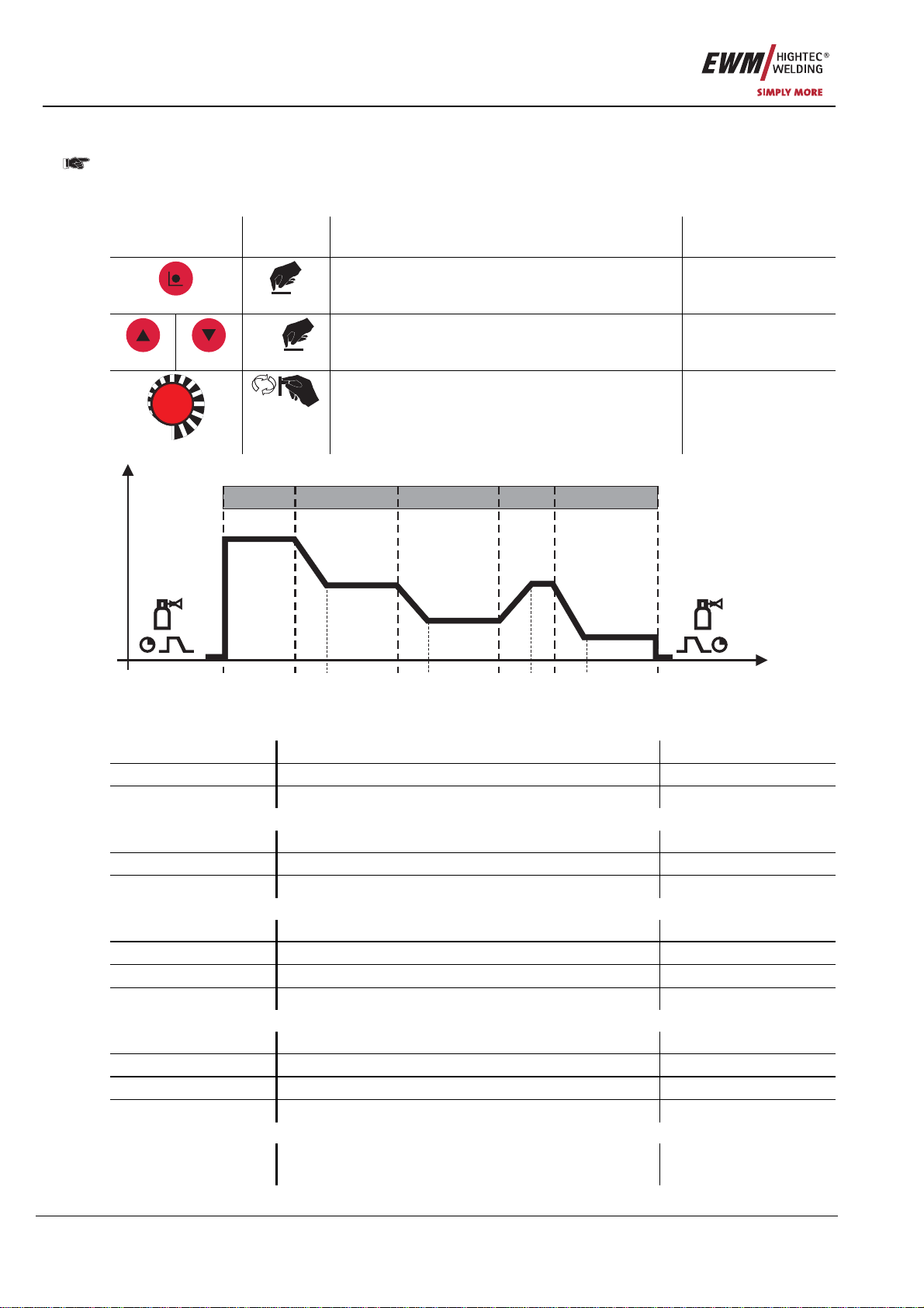
5.2.2.3 Specify program down parameter
After the initial selection of a program, the relevant operating point is set as described in the
"MIG/MAG operating point" chapter.
Operating points are saved and will be available once again after the program is selected.
Operating
element Action Result Display
Select program down parameter setting DVstart : 120%
n x Select down parameter to be set Ustart : +0.0V
m/min
Set down parameter Ustart : +4.2V
DVstart
DV3
U3 DVend
Uend
Ustart
tstart tS1 t2 tS2 t3 tS3 tSe tend
P
START
P
A
P
A
P
B
P
END
t
I
Figure 5-1
Start program PSTART
DVstart Wire-feed speed, relative 1% to 200%
Ustart Arc length correction -9.9 V to +9.9 V
tstart Duration 0.0 s to 20.0 s
Main program PA
tS1 Slope duration from PSTART to PA0.0 s to 20.0 s
t2 Duration (spot time and superpulse) 0.01 s to 20.0 s
tS2 Slope duration from PAto PB0.00 s to 20.0 s
Reduced main program PB
DV3 Wire-feed speed, relative 1% to 200%
U3 Arc length correction -9.9 V to +9.9 V
t3 Duration 0.01 s to 20.0 s
tS3 Slope duration from PBto PA0.00 s to 20.0 s
End program PEND
tSe Slope duration from PAto PEND 0.0 s to 20 s
DVend (r) Wire-feed speed, relative 1% to 200%
Uend Arc length correction -9.9 V to +9.9 V
tend Duration (superpulse) 0.0 s to 20 s
Superpulse function
Superpuls xx Superpulse function On
Off
Functional characteristics
Switching on and system diagnosis
Item No.: 099-008088-EWM01 13
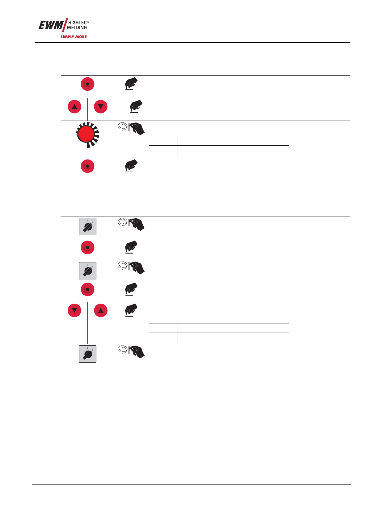
5.2.2.4 Changing over between standard MIG welding and pulse arc MIG welding
Operating
element Action Result Display
3 s
Select setting option Pul / Nor?
n x Select program Px: _Nor
Changeover
^Pul MIG pulse arc welding
m/min
_Nor Standard MIG welding
Confirm and save change
Px: ^Pul
5.2.2.5 Operating point setting changeover via wire feed speed or panel thickness
• The operating point in program 0 can also be set via the panel thickness parameter.
Operating
element Action Result Display
Switch off the welding machine.
+
+
Hold down "Mode" button on the remote control,
switching on the welding machine. PROGRAMME: 0XX
Press "Mode" button once DV
Operating point setting changeover via wire
speed or panel thickness.
DV Wire speed
th/mm Panel thickness
th/mm
Switch off the welding machine and restart in
order to put the change into effect.
5.3 Switching on and system diagnosis
5.3.1 R40 manual remote control
The remote control runs through a system diagnostics process on being switched on. The following
values are displayed.
• PHOENIX R40,001 (Type and initialisation status)
• SV: 00.00.00.XX (Software version)
The current values for the welding voltage and current are then displayed.
• U: 0.0V I: 0A
Commissioning
Proper usage
14 Item No.: 099-008088-EWM01
6Commissioning
6.1 Proper usage
Only connect to remote control connection on the welding machine or wire feed unit.
• Observe the operating instructions for the welding machine or wire feed unit.
• Switch off the welding machine first.
6.1.1 For operation only with the following equipment
PHOENIX R10 PHOENIX R20 PHOENIX R40
• PHOENIX BASIC
• PHOENIX PROGRESS
• PHOENIX EXPERT
• PHOENIX PROGRESS
• PHOENIX EXPERT
• PHOENIX PROGRESS
• PHOENIX EXPERT
PHOENIX R20: An M3.70 or M3.71 type wire feed control is mandatory.
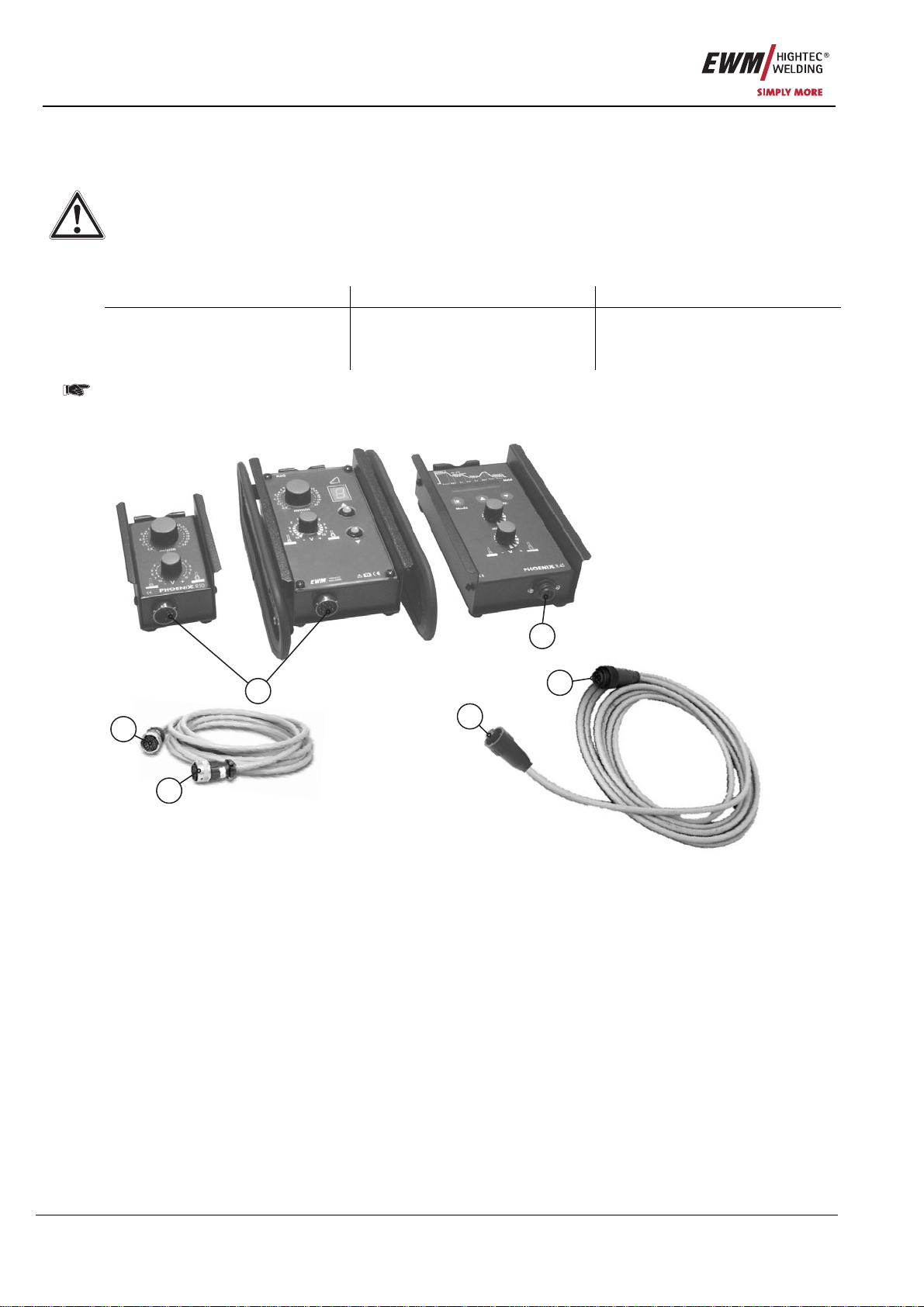
6.2 Establishing the connections
1
2
3
6
4
5
Figure 6-1

Commissioning
Establishing the connections
Item No.: 099-008088-EWM01 15
Item Symbol Description 0
1 Connection socket, 7-pole (digital)
Connection to the digital remote control connection on power source or wire feed unit.
2 Connector plug, 7-pole, female
3 Connector plug, 7-pole, male
4 19-pole connection socket (analogue)
For connecting the control lead.
5 Connector plug, 19-pole, female
6 Connector plug, 19-pole, male
• Switch off the welding machine.
• Insert female connector plug into the remote control connection socket and lock by turning to the right.
• Insert male connector plug into the remote control connection socket on the welding machine and lock
by turning to the right.
The welding machine detects the remote control automatically after being switched on.
Maintenance and testing
General
16 Item No.: 099-008088-EWM01
7Maintenance and testing
7.1 General
When used in the specified environmental conditions and under normal operating conditions, this
machine is largely maintenance-free and requires a minimum of care. However, a number of points
should be observed to guarantee fault-free operation. These include regular cleaning and checking, as
described below, depending on the level of contamination in the environment and the usage time.
7.2 Cleaning
To do this, carefully disconnect the machine from all electrical contacts.
For machines with a separate power supply it is not sufficient simply to switch off the machine
(including the fuse).
In this case, unplug the mains plug and wait for at least two minutes.
Surfaces and glass can be cleaned using standard household cleaners; other elements can be cleaned
as follows:
• Only ever vacuum electrical or electronic components using a vacuum cleaner; never blast with
compressed air.
7.3 Maintenance
All electrical connections and all moveable parts must be tested regularly for correct functioning and to
identify any defects.
In the event of damage, the machine may only be repaired by a specialist engineer, or your contractual
partner.
7.4 Disposing of equipment
This machine does not belong in household waste, in accordance with the German Law on
Electrical Equipment Waste.
In Germany, waste equipment from private households can be disposed of free of charge at local
community collection points. Your administrative office will be pleased to inform you of the options.
EWM participates in an approved waste disposal and recycling system and is registered in the Used
Electrical Equipment Register (EAR) under number WEEE DE 57686922.
In addition, within Europe the machine can also be returned to your EWM sales partner.
7.4.1 Manufacturer's declaration to the end user
• In accordance with European guidelines (Directive 2002/96/EC from the European Parliament and the
Council of 27.01.03), it is no longer permissible to dispose of used electrical and electronic equipment
in unsorted household waste collections. It must be kept separate from other waste. The symbol on
the wheeled bins indicates the requirement to separate this waste.
Help to protect the environment and ensure that this equipment, when you no longer want to use it, is
disposed of in the relevant system of separated waste disposal.
• In Germany, (German Law on the Distribution, Return and Environmentally-Friendly Disposal of
Electrical and Electronic Equipment (ElektroG) of 16.03.05) you are required to take old equipment to
a waste collection point separated from household waste. The public waste disposal contractor (local
authorities) have set up collection points for this purpose where old equipment from private
households in your area can be collected for you free of charge.
It is also possible that the legally responsible waste disposal company will collect old equipment from
private households.
• Please obtain the relevant information from your local waste calendar or from your town council or
local authority on the options available in your area for returning or collecting old equipment.

Warranty
General Validity
Item No.: 099-008088-EWM01 17
8Warranty
8.1 General Validity
3-year warranty
on all new EWM machines*:
• Power sources
• Wire feeds
• Cooling units
• Trolleys
* If these are operated with genuine EWM accessories (such as intermediate tube package, remote
control, remote control extension cable, coolant, etc.).
1-year warranty on:
• Used EWM machines
• Automation and mechanisation components
• Remote control
• Inverters
• Intermediate tube packages
6-month warranty on:
• Spare parts supplied separately (such as circuit boards, ignition units)
Manufacturer/supplier warranty on:
• All additional parts used by EWM, but manufactured by other companies (e.g. motors, pumps, fans,
torches, etc.)
Non-reproducible software errors and parts subject to mechanical ageing are excluded from the warranty
(e.g. wire feed unit, wire feed rollers, replacement and spare wire feed parts, wheels, solenoid valves,
workpiece leads, electrode holders, connection tubes, replacement torches and spare torch parts, mains
and control leads, etc.).
These terms shall apply without affecting the customer’s legal rights to a warranty and subject to our
General Terms and Conditions of Business and our terms on the warranty declaration. Agreements to the
contrary must be confirmed by EWM in writing.
Our General Terms and Conditions of Business are available for access anytime online at www.ewm.de.

Warranty
Warranty Declaration
18 Item No.: 099-008088-EWM01
8.2 Warranty Declaration
Your 3-year warranty
Regardless of statutory warranty rights and based on our General Terms and Conditions, EWM
HIGHTEC WELDING GmbH provides a 3-year warranty for its welding products starting on the date of
purchase. Different warranty periods apply to accessories and spare parts; please see the “General
Validity” section for these periods. Parts subject to wear are naturally exempt from the warranty.
EWM guarantees the error-free condition of the products in terms of materials and processing. If the
product proves to be defective in terms of materials or processing within the warranty period, you are
entitled to free repair or to replacement with an appropriate product, at our discretion. On receipt by EWM
the returned product becomes the property of EWM.
Condition
The prerequisite for receiving the full 3-year warranty is simply to operate the products in accordance with
the EWM operating instructions observing the relevant legal recommendations and guidelines and having
annual maintenance work and testing conducted by an EWM sales partner (see “Maintenance and
testing” chapter). This is because only machines that are maintained regularly function correctly in the
long term.
Making a claim
When making a claim under the warranty, please contact your EWM authorised sales partner only.
Warranty exclusions
No warranty claims can be accepted if the EWM products in question are not operated using genuine
EWM accessories (such as intermediate tube package, remote control, remote control extension cable,
coolant, etc.). The warranty does not apply to products that are damaged due to accidents, misuse,
improper operation, incorrect installation, use of force, disregard of the specifications and operating
instructions, inadequate maintenance (see chapter “Maintenance and testing”), exterior influences, acts of
God or personal misfortunes. Furthermore, it is not valid in the case of improper changes, repairs or
modifications. In addition, a claim for warranty does not exist in the case of partially or completely
dismantled products and interventions by persons who are not authorised by EWM, as well as in the case
of normal wear.
Limitation
All claims regarding fulfilment or non-fulfilment on the part of EWM from this declaration in connection
with this product are limited as follows to the replacement of the actual damages. EWM’s liability
stemming from this declaration in connection with this product is fundamentally limited to the amount that
the purchaser originally paid for the original purchase. This limitation does not apply to personal injuries
or damage to property caused by negligent behaviour on the part of EWM. In no way will EWM be
responsible for lost profits, indirect or subsequent damage. EWM is not liable for damages based on the
claims of third parties.
Place of jurisdiction
If the person making the claim is a business person, the sole place of jurisdiction for all disputes resulting
directly or indirectly from the contractual relationship shall be the headquarters or the branch office of the
supplier, at the discretion of the supplier. The purchaser gains ownership of the products supplied as
replacements within the framework of the warranty adjustment at the time of the exchange.

Accessories, options
Connection and extension cables
Item No.: 099-008088-EWM01 19
9Accessories, options
9.1 Connection and extension cables
Type Designation Item no.
RA5 19POL 5M Remote control e.g. connection cable 092-001470-00005
RA10 19POL 10M Remote control e.g. connection cable 092-001470-00010
RA20 19POL 20M Remote control e.g. connection cable 092-001470-00020
FRV5-L 7POL Extension/connecting cable 092-000201-00003
FRV10-L 7POL Extension/connecting cable 092-000201-00000
FRV20-L 7POL Extension/connecting cable 092-000201-00001
Circuit diagrams
PHOENIX R10
20 Item No.: 099-008088-EWM01
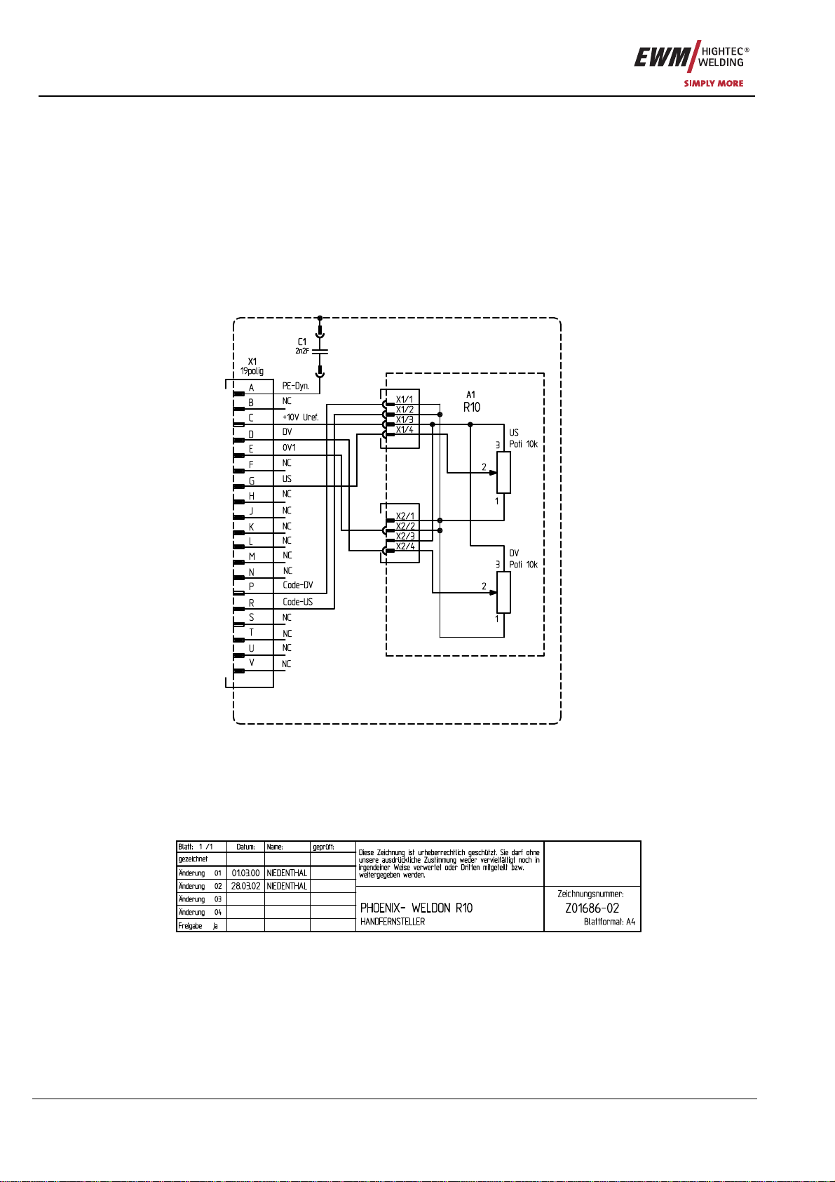
10 Circuit diagrams
10.1 PHOENIX R10
Figure 10-1
This manual suits for next models
2
Table of contents
Popular Remote Control manuals by other brands

Sanyo
Sanyo POA-RCKIT04 operating instructions

McIntosh
McIntosh UR12 owner's manual

Universal Remote Control
Universal Remote Control ORION MX-850 owner's manual

Zte
Zte ZXSDR R8860 Technical manual

Magnum Energy
Magnum Energy ME-ARC owner's manual

Sony
Sony CDX-T68PKG - Cdxt68x & Rmx69rf operating instructions


