Magnum Energy ME-ARC User manual

Owner’s Manual
(for Revision 2.1 or higher)
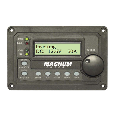
Inverting
DC 12.6V 50A
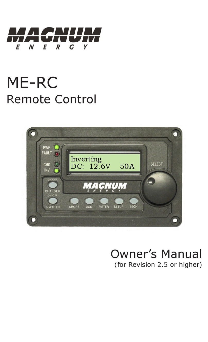
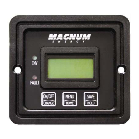
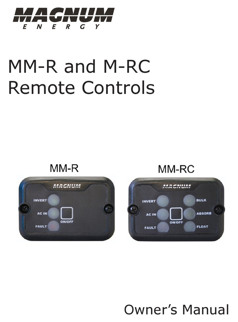
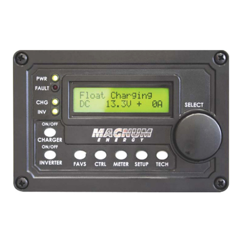
ME-ARC
Remote Control
http://www.wholesalesolar.com/inverter_systems.html

Disclaimer of Liability
Since the use of this manual and the conditions or methods of installation,
operation, use and maintenance of the ME-ARC are beyond the control of
Magnum Energy Inc., this company does not assume responsibility and
expressly disclaims liability for loss, damage or expense, whether direct,
indirect, consequential or incidental, arising out of or anyway connected with
such installation, operation, use, or maintenance.
Due to continuous improvements and product updates, the images shown in
this manual may not exactly match the unit purchased.
Restrictions on Use
The ME-ARC remote shall not be used in connection with life support systems,
life saving or other medical equipment or devices. Using the ME-ARC with this
particular equipment is at your own risk.
Important Product Safety Instructions
This manual contains important safety instructions that must be followed
during the installation and operation of this product. Read all instructions
and safety information contained in this manual before installing or using
this product.
• All electrical work must be performed in accordance with local, state and
federal electrical codes.
• This product is designed for indoor / compartment installation. It must not
be exposed to rain, snow, moisture or liquids of any type.
• Use insulated tools to reduce the chance of electrical shock or accidental
short circuits.
• Remove all jewelry such as rings, watches, bracelets, etc., when installing
or performing maintenance on the inverter.
• Always disconnect the batteries or energy source prior to installing or
performing maintenance on the inverter. Live power may be present at more
than one point since an inverter utilizes both batteries and AC. Turning off
the inverter may not reduce this risk. As long as AC power is connected, it
will pass thru the inverter regardless of the power switch on the inverter or
the ON/OFF INVERTER button on the remote.
Safety Symbols
To reduce the risk of electrical shock, fire, or other safety hazard, the fol-
lowing safety symbols have been placed throughout this manual to indicate
dangerous and important safety instructions.
WARNING: This symbol indicates that failure to take a specified
action could result in physical harm to the user.
CAUTION: This symbol indicates that failure to take a specified ac-
tion could result in damage to the equipment.
Info: This symbol indicates information that emphasizes or supple-
ments important points of the main text.
Remedy: This symbol provides possible solutions for related is-
sues.
http://www.wholesalesolar.com/inverter_systems.html

© 2010 Magnum Energy, Inc. i
Table of Contents
1.0 Overview .................................................................................. 1
2.0 Installation............................................................................... 2
2.1 Installation Guidelines ............................................................... 2
2.2 Tools Required.......................................................................... 2
2.3 Flush Mount Installation Procedure .............................................. 2
2.4 Bezel Mount Installation Procedure .............................................. 3
2.5 Power-up Routine...................................................................... 4
3.0 Setup........................................................................................ 5
3.1 Navigating the Remote’s Menu.................................................... 5
3.2 Pushbuttons and Menu Items...................................................... 7
3.2.1 FAVS Button.........................................................................7
3.2.2 CTRL (Control) Button ........................................................... 9
01 ACIn Control ........................................................................ 10
02 CHG (Charge) Control............................................................ 10
03 GEN Control ......................................................................... 11
3.2.3 METER Button .................................................................... 13
02 AC Meters............................................................................ 14
03 AGS Meters.......................................................................... 14
04 BMK Meters.......................................................................... 16
3.2.4 SETUP Button .................................................................... 18
01 Remote Setup ...................................................................... 19
02 Invert Setup ........................................................................ 20
03 Charger Setup...................................................................... 23
04 AGS Setup ........................................................................... 29
05 BMK Setup........................................................................... 30
3.2.5 TECH Button ...................................................................... 30
4.0 Menu Map: Section 1-4 ...................................................... 34-37
5.0 Operation ............................................................................... 38
5.1 Front Panel ............................................................................ 38
5.1.1 LED Indicators.................................................................... 38
5.1.2 LCD Display ....................................................................... 38
5.1.3 ON/OFF Pushbuttons ........................................................... 39
5.1.4 Menu Pushbuttons .............................................................. 39
5.1.5 Rotary SELECT Knob ........................................................... 39
5.2 Operating the Inverter/Charger................................................. 40
5.2.1 Inverter Mode .................................................................... 40
5.2.2 Charger Mode .................................................................... 40
5.3 System Status Messages.......................................................... 41
5.3.1 Inverter Mode Messages .................................................... 41
5.3.2 Charger Mode Messages..................................................... 42
5.3.3 Fault Mode Messages ......................................................... 47
5.3.3.1 System Fault Messages ................................................. 47
5.3.3.2 Stacking Fault Messages ................................................ 52
5.3.3.3 Internal Fault Messages ................................................ 53
5.3.4 LED Indicator Guide ............................................................ 54
6.0 Troubleshooting ..................................................................... 55
6.1 Troubleshooting Tips................................................................ 56
6.1.1 Inverter Problems............................................................... 56
6.1.2 Charger Problems ............................................................... 56
6.2 Performing an Inverter Reset.................................................... 57
6.3 Powering Down the Inverter ..................................................... 57
7.0 Limited Warranty.................................................................... 58
http://www.wholesalesolar.com/inverter_systems.html

ii © 2010 Magnum Energy, Inc.
List of Figures
Figure 1-1, Front Panel Features.......................................................... 1
Figure 2-1, Remote Cutout Dimensions................................................. 3
Figure 2-2, Remote Bezel Dimensions .................................................. 3
Figure 2-3, Remote Control Connections ............................................... 4
Figure 2-4, Power Up Routine.............................................................. 4
Figure 3-1, Front Panel Set-up Features................................................ 5
Figure 3-2, SETUP Menu Navigation ..................................................... 6
Figure 3-3, FAVS Button ..................................................................... 8
Figure 3-4, CTRL Button ..................................................................... 9
Figure 3-5, Meter Button .................................................................. 12
Figure 3-6, Setup Button .................................................................. 18
Figure 3-7, TECH Button................................................................... 30
Figure 4-1, Inverter/Charger Menu Map (Pages 1 - 4)...................... 34-37
Figure 5-1, ME-ARC Front Panel Controls and Indicators........................ 38
Figure 5-2 to 5-5, Inverter Modes................................................. 41-42
Figure 5-6 to 5-15, Charging Modes .............................................. 42-46
Figure 5-16, Low Battery Fault .......................................................... 47
Figure 5-17, High Battery Fault ......................................................... 47
Figure 5-18, Overtemp Fault ............................................................. 48
Figure 5-19, AC Overload Fault.......................................................... 48
Figure 5-20, AC Backfeed Fault.......................................................... 48
Figure 5-21, High Volts AC Fault ........................................................ 49
Figure 5-22, Dead Battery charge Fault .............................................. 49
Figure 5-23, Overcurrent Fault .......................................................... 49
Figure 5-24, FET Overload Fault......................................................... 50
Figure 5-25, Breaker Tripped Fault ..................................................... 50
Figure 5-26, Unknown Fault .............................................................. 50
Figure 5-27, Tfmr Overtemp Fault...................................................... 51
Figure 5-28, Fatal Error $ Fault.......................................................... 51
Figure 5-29, No Inverter Comm......................................................... 51
Figure 5-30, StackClock Fault............................................................ 52
Figure 5-31, Stack Mode Fault........................................................... 52
Figure 5-32, StackPhase Fault ........................................................... 52
Figure 5-33, Internal Bridge Fault ...................................................... 53
Figure 5-34, Internal Charger Fault .................................................... 53
Figure 5-35, Internal NTC Fault ......................................................... 53
Figure 5-36, Internal Relay Fault ....................................................... 53
Figure 6-1, Performing an Inverter Reset ............................................ 57
List of Tables
Table 3-3, Battery Type to Charge Voltages ......................................... 24
Table 5-1, LED Indicator Guide .......................................................... 54
Table 6-1, Remote Control Troubleshooting Guide ................................ 55
http://www.wholesalesolar.com/inverter_systems.html
© 2010 Magnum Energy, Inc. 1
1.0 Overview
1.0 Overview
The ME-ARC remote control allows you to monitor and customize the operating
parameters for your Magnum inverter/charger. It is the same remote used
on all Magnum inverter/charger models in the ME, MM, MS, MS-AE, MS-PAE
and RD Series lines so there is no cross-platform confusion.
The ME-ARC50 comes standard with a 50 foot, 4-conductor (twisted-pair)
telephone cable and includes non-volatile memory (preserves adjustable
settings, even if power to the remote or inverter is removed). The Magnum
remote control includes all of the programming and operation functions in-
cluded in an easy-to-use package.
Info: This manual is for the ME-ARC with revision 2.1 or higher; see
the TECH: 02 Revisions display on page 16 for information on how
to determine your revision level.
The ME-ARC is equipped with the following features:
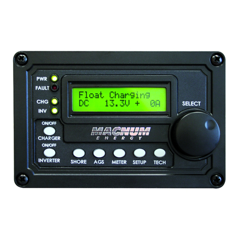
• LED Indicators - The at-a-glance LEDs provide the inverter/charger
status in a straightforward way.
• LCD Display - The LCD display is a 16 x 2 line (32 characters total),
alphanumeric display used for setting up the inverter/charger operation, as
well as viewing current status or fault messages.
• ON/OFF Pushbuttons (x2) - Allows the inverter or charger to be
independently and quickly enabled or disabled.
• Menu Pushbuttons (x5) - The menu pushbuttons allow the inverter or
charger to be configured to your specific system preferences. These menus
also allow simple access to menu items that can help with monitoring and
troubleshooting your inverter/charger system.
• Rotary Knob / SELECT button - The rotary encoder knob is similar
to a dash radio knob and is used to quickly scroll through and select various
menu items and settings. Pushing this rotary knob allows you to “SELECT” a
menu item, or to “Save” a setting once it is displayed on the LCD screen.
Inverting
DC 12.6V 50A
Figure 1-1, Front Panel Features
http://www.wholesalesolar.com/inverter_systems.html
2 © 2010 Magnum Energy, Inc.
2.0 Installation
2.0 Installation
Before installing the remote, read the entire installation section to determine
how you are going to install your ME-ARC. The more thorough you plan in the
beginning, the better your inverter needs will be met.
Info: Installations should be performed by qualified personnel, such
as a licensed or certified electrician. It is the installer’s responsibility
to determine which safety codes apply and to ensure that all appli-
cable installation requirements are followed. Applicable installation
codes vary depending on the specific location and application.
Info: Review the “Important Product Safety Information” on the
front inside cover page before any installation.
2.1 Installation Guidelines
• Before connecting any wires, determine the remote cable route throughout
the home or vehicle/boat, both to and from the inverter.
• Always check for existing electrical, plumbing or other areas of potential
damage BEFORE drilling or cutting into walls to mount the remote.
• Make sure all wires have a smooth bend radius and do not become
kinked.
• If installing this remote in a boat, RV or truck; ensure the conductors pass-
ing through walls, bulkheads or other structural members are protected to
minimize insulation damage such as chafing, which can be caused by vibration
or constant rubbing.
2.2 Tools Required
Installing the remote control is a simple process and requires the following
tools:
• Phillips screwdriver • Level • Drill
• Cut-out tool (knife/saw) • Pencil • Drill bit (7/64”)
2.3 Flush Mount Installation Procedure
1. Select an appropriate location to install the remote control. Allow ample
room to access the remote’s adjustment dial and to view the LEDs. Ensure
the viewing angle of the display is appropriate.
2. Refer to Figure 2-1 for hole and cutout dimensions.
3. Run the remote cable between the remote and the inverter/charger. This
cable is a 4-wire, twisted-pair, telephony standard with RJ11 connectors on
each end. A standard telephone cable may be substituted if the provided
remote cable is not able to be used.
4. Connect the remote cable into the RJ11 “Remote” port (has blue label) on
the inverter/charger (see Figure 2-3).
5. Have the inverter connected to batteries, but ensure the inverter is off and
that no AC power is connected to the inverter.
http://www.wholesalesolar.com/inverter_systems.html
© 2010 Magnum Energy, Inc. 3
2.0 Installation
CUT OUT THIS
AREA
5 1/4"
3 1/4"
2 7/8"
4 7/8"
(diagram notto scale)
Figure 2-1, Remote Cutout Dimensions
Figure 2-2, Remote Bezel Dimensions
2.4 Bezel Mount Installation Procedure
1. Select an appropriate location to install the remote control. Allow ample
room to access the remote’s adjustment dial and to view the LEDs. Ensure
the viewing angle of the display is appropriate.
2. Refer to Figure 2-2 for mounting dimensions. Use the 3 1/4 x 5 1/4 dimen-
sions for mounting the bezel. Mount the remote to the bezel and run the cable
through the notch or out the back of the bezel for best mounting.
3. Run the remote cable between the remote and the inverter/charger. This
cable is a 4-wire, twisted-pair, telephony standard with RJ11 connectors on
each end. A standard telephone cable may be substituted if the provided
remote cable is not able to be used.
4. Connect the remote cable into the RJ11 “Remote” port (has blue label) on
the inverter/charger (see Figure 2-3).
5. Have the inverter connected to batteries, but ensure the inverter is off and
that no AC power is connected to the inverter.
4 3/8 in [110.5 mm]
5 1/4 in [133.35 mm]
5 7 /8 in [148.6 mm]
27/8in [72.4mm]
31/4in [82.55mm]
4 3/8 in [110.5 mm]
27/8in[72.4mm]
http://www.wholesalesolar.com/inverter_systems.html

4 © 2010 Magnum Energy, Inc.
2.0 Installation
Info: All power to operate the remote control is provided by the
inverter/charger through the remote cable.
6. While monitoring the front of the remote, connect the other end of the cable
into the RJ11 jack on the backside of the remote (see Figure 2-3).
7. Immediately upon connecting the remote cable, all the LED’s will come on
as the unit goes through a self-test. After the initial self-test completes, text
should appear with a system status message indicating the current state of
the inverter/charger. If not, please refer to the troubleshooting section.
8. Secure the remote to the wall using the four 6 x 3/4” screws provided.
9. The remote is ready for setup.
REMOTE Port
(blue label)
RJ11 connection
Magnum Inverter
Remote cable
ME-ARC
RemoteControl
(backview)
Figure 2-3, Remote Control Connections
2.5 Power-up Routine
Power up Routine: When the ME-ARC is first connected to the inverter
a power up routine is initialized. During the power up routine the LCD will
read: Magnum Energy, Self Test, (C) 2009, Connecting to..., ME-ARC V #.#,
INV/CHG V #.#.
After the initial power up routine is finished the remote will be displaying
“Set Clock”.
•
Figure 2-4, Power Up Routine
Magnum Energy
Self Test ( C) 2009
Connecting to….. ME-ARCV #.#
INV/CHG V #.#
Status
AM-PM=12:00A
Status
Minute =12:00 A
Status
Hour = 12:00 A
http://www.wholesalesolar.com/inverter_systems.html
© 2010 Magnum Energy, Inc. 5
3.0 Setup
3.0 Setup
When the remote is connected to a Magnum inverter/charger, the settings in
the remote control determine the inverter/charger operating parameters. The
default settings in the remote control (see Table 3-4, Inverter/Charger Default
Settings) are adequate for most installations, however you have the option to
change some of the operating parameters if required. This section will show
you how to navigate the remote, give you an understanding of the function of
each adjustable setting, and help you decide what setting should be used.
3.1 Navigating the Remote’s Menu
The ME-ARC has an internal structure that provides menu items and adjust-
able settings that provide the ability to configure your inverter/charger to
your specific parameters.
Info: See Figure 4-1, Inverter/Charger Menu Map for a complete
map of the inverter/charger menu items and adjustable settings.
Familiarize yourself with the items on the front panel which are used to find,
adjust and save the desired setting. They are:
• LCD Display - The bottom line of the LCD display shows the menu items,
adjustable settings, or the meters display information.
Info: The bottom line of the LCD display returns to the Home Screen
to show DC voltage and current (see Figure 3-1) after 5 minutes - if
no buttons have been pressed.
Info: When the ”←” (left facing arrow) symbol is shown on the
display it indicates that the displayed setting has been selected and
will be used.
• Menu Pushbuttons (x5) - These five buttons allow simple access to the
menu items that can help with configuring, monitoring and troubleshooting
your inverter/charger system.
• Rotary SELECT Knob - This knob allows you to quickly scroll through
and select various menu items and settings. Pushing on the knob selects the
menu item to change or saves this current selection. Refresh the LCD display
by holding this knob down for 7 seconds.
Inverting
DC 12.6V 56A
Rotary
SELECT Knob
LCD
Display
Menu
Pushbuttons
Figure 3-1, Front Panel Set-up Features
http://www.wholesalesolar.com/inverter_systems.html
6 © 2010 Magnum Energy, Inc.
3.0 Setup
Figure 3-2, SETUP Menu Navigation
4. Press the SELECT knob to
change the desired setting.
Top line show menu item.
Bottom line shows current setting*
Set Search Watts
5Watts
Rotate the SELECT knob to the
desired setting.
When the bottom line shows the
desired setting -
5. Press the SELECT knob to
“save” this desired setting.
Inverting
02 Invert Setup
3. Press the SELECT knob.
When the bottom line shows the
desired menu heading -
1. Press the SETUP Menu button .
Bottom line shows a menu
heading.
2. Turn the SELECT knob to the
desired menu heading.
*[if this setting is correct, rotate
the SELECT knob to continue to
the next menu item].
02A Search Watts
OFF
Inverting
01 Remote Setup
http://www.wholesalesolar.com/inverter_systems.html
© 2010 Magnum Energy, Inc. 7
3.0 Setup
3.2 Pushbuttons and Menu Items
The five menu pushbuttons (FAVS, CTRL, METER, SETUP or TECH) allow the
inverter/charger system to be configured to your specific preferences. These
menus also allow you to access menu items that can help with monitoring
and troubleshooting your system.
Read this section to help understand the function of each Menu button and
the configurable settings - to determine if they should be changed to optimize
the operation of the inverter/charger.
3.2.1 FAVS Button
The FAVS button is short for FAVORITES. This button is similar to the Favorites
button on your TV remote, it allows you to store the most frequently used
menu items for quick reference or changes to the system.
This menu button allows 5 menu items to be stored for quick access without
having to find them within the SETUP or other control buttons. The 5 menu
items stored under the FAVS button should be the “favorite” menus most
often used.
Before changing the default FAVS menu items it is suggested that you
thoroughly review all the menu items in the menu map on pages 34 thru 37
and make a short list of the items you think you will use most often. Once
you have determined which 5 items you would like to make your favorites,
then decide in what order you would like those menus to appear under the
FAVS button. This is important since you will assign a FAVS position 1-5 for
each menu item you select to be a FAVS.
Menu items can be changed anytime under the FAVS button. Navigate to the
menu item that you would like to set as a favorite, then push and hold the
FAVS button for 3 seconds. After 3 seconds the screen will show “Select FAV:
F1” on the bottom line. Rotate the knob to select FAVS 1 through 5. Once you
have decided which location you would like the menu item to be in, press the
SELECT knob to save the menu item at the selected location.
Info: The FAVS button can be used to store menu items that would
otherwise not be accessible after a PIN has been set for the SETUP
menu.
Info: Menu “Headings” cannot be stored in FAVS, only menu
“Items”. Menu headings are identified with a number followed by
the Menu heading. Menu items are identified by a number followed
by a letter.
Status
02 Invert Setup
02A Search Watts
5 Watts
Example: “02 Invert Setup” is a menu heading
Example: “02A Search Watts” is a menu item
http://www.wholesalesolar.com/inverter_systems.html
8 © 2010 Magnum Energy, Inc.
3.0 Setup
Default Settings:
Info: Refer to page 6, 3.2.1 FAVS button for information on how to
change a FAVS menu item.
FAVS: F1 Search Watts - Search Watts is the F1 default (FAVS #1). Refer
to page 20 for SETUP 02A Search Watts on how to adjust the Search Watt
setting.
FAVS: F2 LBCO Setting - LBCO (Low Battery CutOut) is the F2 default
(FAVS #2). Refer to page 20 for SETUP 02B LBCO setting on how to adjust
the LBCO setting.
FAVS: F3 AC Input Amps - AC Input Amps is the F3 default (FAVS #3).
Refer to page 24 for SETUP 03A AC Input Amps on how to adjust the AC
Input Amps
FAVS: F4 Battery Type - Battery Type is the F4 default (FAVS #4). Refer to
page 24 for SETUP 03B Battery Type on how to set the Battery Type.
FAVS: F5 Gen Control - Gen Control is the F5 default (FAVS #5). Refer to
page 11 for CTRL 03 Gen Control on how to operate the Gen Control func-
tion.
F1 Search Watts
5 Watts
Rotary
SELECT Knob
LCD
Display
FAVS
Button
Figure 3-3, FAVS Button
Press to edit
setting
press
FAVS
rotate to
desired
selection:
F1 Search Watts
5 Watts
Top line shows current
FAVS menu and position
in FAVS menu
Bottom line shows current
setting. Push Select to edit
current setting
To select the next
FAVS item
F5 GenControl
OFF
F2 LBCO Settting
10.0 VDC F3 ACInput
Amps = 30A F4 Battery Type
Flooded
F1 Search Watts
5 Watts
The FAVS button has five default menu items stored from the factory and
may be changed by accessing menu items using the METER, SETUP or TECH
button.
http://www.wholesalesolar.com/inverter_systems.html

© 2010 Magnum Energy, Inc. 9
3.0 Setup
3.2.2 CTRL (Control) Button
The CTRL menu button contains the menus for “ACIN CONTROL”, “CHG CON-
TROL” and “GEN CONTROL”. The CTRL button gives you quick control of the
main functions of the inverter/charger without having to access the SETUP
menus in order to change operation of the inverter/charger or generator.
The SETUP menus are used to program all of the user settings for opera-
tion of the inverter/charger and accessories. Once the settings have been
programmed in the SETUP menus the features can then be enabled using
the CTRL button.
Example: In the SETUP menu “02C AC In - Time” you set the time of day
(e.g. 12AM to 8AM) that you want the inverter to connect to the incoming
AC. Once this time is set in the setup menu use the CTRL button to access
the “ACIn Control” menu and select “Time Connect”. When “Time Connect”
is selected the inverter/charger will only connect to AC when the time is
between 12AM and 8AM.
01 ACIn Control
Auto Connect
Rotary
SELECT Knob
LCD
Dis
p
la
y
CTRL
Button
Figure 3-4, CTRL Button
press to select
CTRL
press 01 ACIn Control
Auto Connect
rotate to
press to select
rotate to
desired
selection:
01 ACIn Control
Auto Connect 03 Gen Control
OFF
02 CHG Control
Multi-Stage
Top line shows
menu heading
http://www.wholesalesolar.com/inverter_systems.html

10 © 2010 Magnum Energy, Inc.
3.0 Setup
02 CHG (Charge) Control
CHG Control allows you to set the Charger Mode for Multi-Stage, always stay
in Float, Restart Bulk which restarts the Multi-Stage charge profile. Most of
the time the charger should be left in the multi-stage setting but if you want
to override this setting use the CTRL button and CHG Control menu to change
the charger profile.
Multi-Stage: This charge profile starts in “Bulk” (maximum current until
the Absorption voltage is reached), then transitions to the Absorption cycle
(Absorption cycle as determined by the settings in SETUP menu 03E Absorb
Done), and finally transitions to the final charge stage as selected in SETUP
menu 03G Final charge.
Info: Any time during the charge cycle the charger may be “forced”
into Float or Rebulk, using Force Float or Restart Bulk from the CTRL
button 02 CHG Control menu.
Info: Multi-Stage must be selected in order for the Final Charge
Stage selected in menu 03G Final Charge Stage to be used.
Multi Connect: Automatically connects to incoming AC power when the in-
coming AC is qualified by the inverter/charger (voltage is above VAC Dropout
setting and between 50Hz to 70Hz for domestic models, and 40Hz to 60Hz
for export models).
VDC Connect: Connects to incoming AC when the DC battery voltage is below
the “Set Connect Volts” setting in menu “02D AC In - VDC”, and disconnects
from incoming AC when the DC battery voltage is above the “Set Disconnect
Volts”, also in menu “02D AC In - VDC”.
Time Connect: Connects to incoming AC when the time of day is between
the “Connect Time” and “Disconnect Time” in menu “02C AC In - Time”.
AC In: Disabled - Disconnects incoming AC when selected. This setting will
prevent incoming AC from connecting to the inverter/charger.
Info: The top status line of the LCD display will alternate the inverter/
charger status with a secondary AC IN status if AC is present, but not
connecting as a result of a selection made in the SETUP menu.
Example: AC is present but AC IN -Time has been selected in the 01
ACIn CTRL menu, and the current time of day 2PM. In menu 02C AC
In-Time the current setting is 12AM - 8AM. The current time of 2PM
is outside the connect time so the inverter/charger will not connect
to the incoming AC until after 12AM. The primary status will display
“Inverting” and the secondary status will display “Time Connect” to
let you know the reason that incoming AC has not connected.
Info: See SETUP menus 02C and 02D on pages 21 and 22 for
complete explanation of VDC Connect and Time Connect menu
settings.
01 ACIn Control
AC In Control has four different conditions in which the inverter/charger will
connect to incoming AC power. Only one condition may be set at any one
time. Refer to the Setup section for information on how to use each of the
following settings.
http://www.wholesalesolar.com/inverter_systems.html

© 2010 Magnum Energy, Inc. 11
3.0 Setup
03 GEN Control
GEN Control is used for controlling a standby generator connected to the
system using the optional ME-AGS-N. Once the ME-AGS-N is installed in the
system, the generator can be manually started and stopped or set to the auto
start and stop mode from the GEN Control menu.
Info: The ME-AGS-N, Multi Gen Start Network, version must be
installed in order for the 03 GEN Control menu to control a standby
generator. Refer to the ME-AGS-N manual for more information on
controlling standby generators.
OFF: The OFF selection turns the generator OFF if it is running from either a
manual start or auto start command. When the OFF position is selected the
generator will not start automatically.
Info: If DC power is lost to the remote, this menu resets to the
default OFF position for safety.
Restart Bulk: This selection restarts the Bulk cycle from any stage in the
charge cycle. Restarting the Bulk stage is useful when a full Multi-stage
charge cycle does not bring the specific gravity of the batteries to the
proper level.
Info: Restart Bulk will default back to the Multi-Stage once the
inverter/charger status displays “Bulk Charging”.
Info: If you have to continually restart the Bulk cycle in order to
bring the batteries to full charge, check the settings in SETUP menu
“03 Charger Setup” to make sure the batteries are fully charged at
the end of a regular multi-stage charge cycle. Check with your bat-
tery manufacture for proper battery charger settings.
CAUTION: Frequently restarting Bulk may result in overcharging
of the batteries.
Force Float: This charge profile “forces” the charger to stay in the Float mode
as long as AC is present and the charger is active. Force Float is most often
used when another source of charging such as PV, wind or hydro is available
to keep the batteries at or above the Float voltage. If AC is disconnected and
then reconnected the charger will go directly to the Float mode and will not
do a Bulk or Absorption charge cycle.
CAUTION: Using the Force Float mode may not fully charge the
batteries. Most batteries require a Bulk and Absorption charge cycle
in order to fully recombine the electrolyte in the batteries and bring
the specific gravity to the proper level. Be sure to check with your
battery manufacture before using this setting.
Info: If Silent is selected in menu 03G Final Charge Stage you can
override this selection with Force Float to temporarily Float the
batteries.
http://www.wholesalesolar.com/inverter_systems.html
12 © 2010 Magnum Energy, Inc.
3.0 Setup
Inverting
01 DC Meters
Rotary
SELECT Knob
LCD
Display
METER
Button
Figure 3-5, Meter Button
AUTO: This selection uses the settings in “04 AGS Setup” to automatically
start and stop the generator. Refer to menu 04 AGS Setup on page 29 to set
the start and stop parameters for the generator.
ON: The ON selection will start the generator by sending a “start” command
from the ME-AGS-N control module. Once the generator is started it may
be stopped by selecting OFF from the GEN Control menu, this sends a stop
command from the ME-AGS-N control module.
Info: You can manually start the generator by selecting ON from the
GEN Control menu, and then change the selection to AUTO to auto-
matically stop the generator. When the AUTO setting is selected after
the generator has been manually started it will use the STOP setting
in menu 04A “Set Stop Gen Volts” or menu 04F “Max Gen Run Time”,
whichever occurs first. This setting is useful if you want to make sure
the generator starts before you leave, but also want to make sure
the generator doesn’t run too long, thereby wasting fuel.
The start selection uses warm-up time. The stop selection stops im-
mediately it does not use the cool-down time.
Press to
select meters
press
METER
rotate to
desired
selection:
Status
01 DC Meters
Top line shows inverter/
charger status
Bottom line shows current
menu heading
To select the next
Meter menu
Status
02 ACMeters Status
03 AGS Meters Status
04 BMK Meters
Status
01 DC Meters
http://www.wholesalesolar.com/inverter_systems.html

© 2010 Magnum Energy, Inc. 13
3.0 Setup
3.2.3 METER Button
Pressing the METER button gives you access to different meters, which helps
determine the status of the inverter/charger and battery system.
Info: Some meter functions may not be accessible with older
inverter software. If some meters do not function check for current
inverter software.
Info: All displays will automatically returns the “Home” screen 5
minutes after the last button push; unless you are on a display in
the METER menu where the screen will stay without returning to
the “Home” screen. This feature is useful for displaying commonly
used meter readings like SOC, where it is useful to see the battery
status “at a glance”.
01 DC Meters - DC Meters display battery voltage, DC amps from the
inverter/charger and the time in charge mode. Use these meters to monitor
your battery bank.
01A DC Volts: This menu provides the DC battery voltage. The DC:
V (Volts) display provides the voltage from the batteries connected to the
inverter. The DC: V accuracy is ±1.5% with a 0.1 VDC resolution.
01B DC Amps: While inverting, the DC: A (Amps) displays a negative
number to show the battery current used by the inverter. If in charge
mode, the DCA (amps) displays a positive number to show the amount
of current delivered to the batteries. The accuracy of this display below
1 amp AC (~10 amps DC @ 12VDC) is not detected. When the current
in or out of the batteries is greater than 1 amp AC, the display accuracy
is ±20%.
01C Charge Time: This meter reads whenever the charger is in the
Bulk or Absorb mode. The meter does not accumulate time when in
Float, Charger Standby, Full or Silent mode.
Info: Once the charger leaves the absorption mode and enters the
“Final Charge Stage”, this timer is reset and will not accumulate until
the charger reenters the Bulk or Absorption charge mode.
•
•
•
http://www.wholesalesolar.com/inverter_systems.html
14 © 2010 Magnum Energy, Inc.
3.0 Setup
02 AC Meters
02A Output Volts: This provides the AC voltage measurement at
the inverter’s output terminals. If inverting, this would measure the
inverter’s output voltage. If in charging mode, this would measure the
AC voltage that is passing through the inverter from the source (e.g.
grid or generator).
02B Output Hertz: While inverting, this menu displays the output fre-
quency of the inverter in Hertz. This menu provides the AC Output Hertz
on the output of the inverter at the inverter AC output terminals. When
the AC input is connected to an incoming AC source, this display shows
the frequency (Hertz) of the incoming AC source (i.e. grid or generator)
that is passing through the inverter to the inverter output terminals.
02C Load Amps: This menu displays the load the inverter is running in
the Inverting mode in AC amps measured at the inverter output terminals.
This number is always displayed as a positive number.
02D Input Amps: This menu displays the total AC amps being used by
the inverter for charging and any connected load at the output of the
inverter.
Example: If the charger is using 20A from the AC source and the load con-
nect to the inverter output is using 10A, the combined load on the incoming
AC source is 30A. So, 30A would be displayed as the Input Amps.
Info: The 02D Input Amps is determined by adding the 02C Load
Amps and the O2E Inv/Chg Amps.
02E Inv/Chg Amps: This menu displays the amps the charger is using
from the AC source.
Info: The 02E Inv/Chg Amps is determined by subtracting the 02C
Load Amps from the 02D AC Input Amps.
•
•
•
•
•
03 AGS Meters
03A AGS Status: There are 26 different status messages that can display
to determine what state the ME-AGS-N is currently in, but only one will be
displayed at any one time.
Info: This menu is most important to determine if the ME-AGS-
N is working correctly, or for troubleshooting an installation of an
ME-AGS-N.
Info: For any “Fault” mode listed in the status menu, please refer to
the ME-AGS-N Owner’s Manual (part number: 64-0005) for trouble-
shooting information.
AC In: The charger is connected to another source, such as grid or an-
other generator and not controlled by the ME-AGS-N.
Info: When AC In is displayed, the AGS is locked out from auto
starting.
Gen Cooldown: The stop setting has been satisfied in one of the genera-
tor start/stop menus and the generator has been disconnected from the
inverter/charger, but is still running until the cooldown time is satisfied
in menu “04J Gen Cooldown Time”.
Gen Warm-up: The generator has successfully started on one of the start
settings, but has not connected to the inverter/charger because it is wait-
ing to satisfy the warm-up time set in menu “04I Gen Warm-up Time”.
•
•
•
http://www.wholesalesolar.com/inverter_systems.html

© 2010 Magnum Energy, Inc. 15
3.0 Setup
Fault Amp: The generator failed to start in the “Start Amps” mode.
Fault Exercise: The generator failed to start in the “Start Exercise”
mode.
Fault MaxRn: The generator exceeded Max Run Time and has turned
off.
Info: The generator will shut down when reaching the Max Run Time
and may still be running if this fault is observed.
Gen Run Fault: The generator successfully started and ran fro more
than 5 minutes, but unexpectedly stopped before the ME-AGS-N could
automatically stop the generator.
Fault SOC: The generator failed to start in the “Start SOC” mode.
Fault Temp: The generator failed to start in the “Start Temp” mode.
Fault Test: The generator failed to start in the “test” mode.
Fault Time: The generator failed to start in the “Start Time” mode.
Fault Topoff: The generator failed to start in the “Start Topoff” mode.
Fault VDC: The generator failed to start in the “Start VDC” mode.
•
•
•
•
•
•
•
•
•
•
•
Manual Run: The generator has be started manually either from the
“03 Gen Control” menu or from a start/stop switch directly connected
to the generator.
No Comm: The ME-AGS-N is not communicating with the ME-ARC re-
mote. Causes could be a bad ME-AGS-N network cable, no power to the
ME-AGS-N, or there is no ME-AGS-N installed in the system.
Off: Generator is off and the AGS will not auto start the generator.
Quiet Time: The ME-AGS-N has entered Quiet Time as set in menu “04G
Quiet Time”. The generator will not auto start during Quiet Time.
Ready: 03 Gen Control is set to Multi, and the ME-AGS-N is ready to
automatically start the generator based on the 04 AGS Setup settings.
Start Amp: The generator has started based on the settings in menu
“04C Gen Run Amps”.
Start Exercise: The generator has started based on the settings in menu
“04H Gen Exercise”.
Start SOC: The generator has started based on the settings in menu
“04D Gen Run SOC”.
Start Temp: The generator has started based on the settings in menu
“04E Gen Run Temp”.
Start Test: The ME-AGS-N is in the test mode. The test mode may be
started from the test button located on the ME-AGS-N (see the manual
for the ME-AGS-N for further information on the test button).
Start Time: The generator has started based on the settings in menu
“04B Gen Run Time”.
Start Topoff: The generator has started based on the settings in menu
“04G Quiet Time”.
Start VDC: The generator has started based on the settings in menu
“04A Gen Run VDC”.
•
•
•
•
•
•
•
•
•
•
•
•
•
http://www.wholesalesolar.com/inverter_systems.html

16 © 2010 Magnum Energy, Inc.
3.0 Setup
03B DC Volts-AGS: This menu displays the DC voltage measured at
pins 3 and 4 of the ME-AGS-N module. This menu is useful in setting
up the voltage start for the AGS and for troubleshooting the operation
of the AGS.
Info: The DC voltage reading in this menu may vary from the DC
voltage reading in menu “01A DC Volts” and “04C DC Volts-BMK”.
Each DC voltage reading is taken at a different place in the system
and therefore there may be wire losses or connections that make
the readings differ. It is important when troubleshooting the system
to read the appropriate related meter for each device i.e. when
troubleshooting the AGS use “03B DC Volts-AGS” for verification
and testing purposes.
03C Gen Run Time: This menu displays the time the generator has been
running since the AGS auto started the generator. This menu does not
display run time when the generator has been manually started.
Info: This hour meter resets each time the generator is stopped.
This meter is useful when trying to determine how long the generator
has been running in the auto mode if you were not present when it
started. This meter does not replace the hour meter for total hours
the generator has run.
03D AGS Temp: The menu displays the temperature of the AGS Temp
sensor (included with ME-AGS-N, but use is optional) and is helpful in
determining proper placement and operation of the AGS temp sensor.
03E Days Since GenRun: This menu displays the number of days since
the generator has last run. This menu is useful in determining if the AGS
start and stop settings are set up correctly.
Info: This meter resets whenever the generator is either auto
started, exercised or manually started. The meter reads the B+ signal
provided by the generator to the AGS module for this meter.
•
•
•
•
04 BMK Meters
04 BMK Meters: These meters display the reading from the optional
ME-BMK, if installed.
04A BMK Status: There are 3 status menus to determine what state
the BMK is in.
BMK Ready: This indicates there is an optional ME-BMK installed in the
system, and that it is powered and communicating with the ME-ARC.
Power-up Fault: This indicates the ME-BMK has failed to properly
power-up during normal installation procedures. Refer to the ME-BMK
manual for troubleshooting information.
No Comm: This indicates the ME-BMK is not communicating with the
ME-ARC. The most common causes are; No ME-BMK installed in the
system, bad network cable, no power to the ME-BMK. Refer to the
ME-BMK for troubleshooting information.
Info: These menus allow the optional ME-BMK (Magnum Energy’s
Battery Monitor Kit) - if installed - to display the status of the
battery system; refer to the ME-BMK Owner’s Manual (part number
64-0013) for detailed information on the Battery Monitor Kit and
these menus.
•
•
http://www.wholesalesolar.com/inverter_systems.html
This manual suits for next models
1
Table of contents
Other Magnum Energy Remote Control manuals

Magnum Energy
Magnum Energy MM Series Operating instructions

Magnum Energy
Magnum Energy ME-MR User manual

Magnum Energy
Magnum Energy ME-RC User manual

Magnum Energy
Magnum Energy ME-MR Series User manual

Magnum Energy
Magnum Energy ME-RC User manual

Magnum Energy
Magnum Energy ME-RC User manual

Magnum Energy
Magnum Energy ME-ARC50 User manual

Magnum Energy
Magnum Energy MM-R User manual

Magnum Energy
Magnum Energy ME-MR User manual

Magnum Energy
Magnum Energy ME-ARC Series User manual