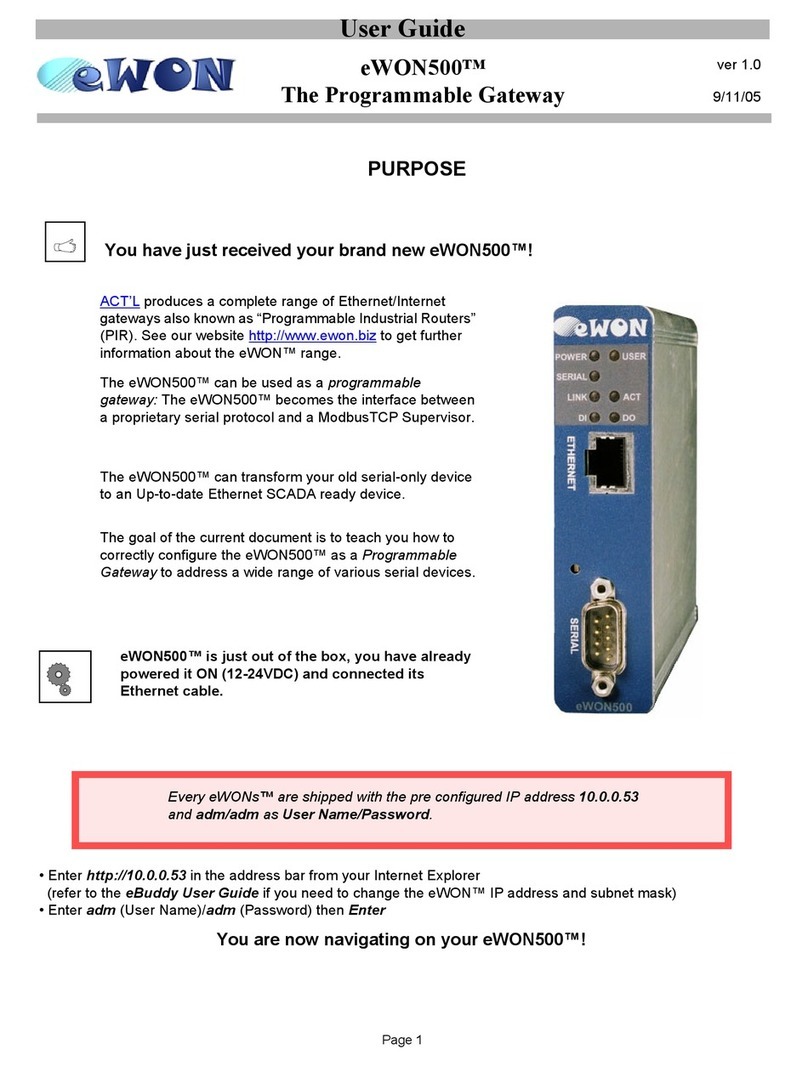
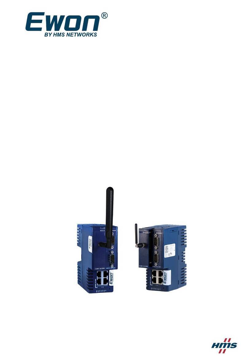
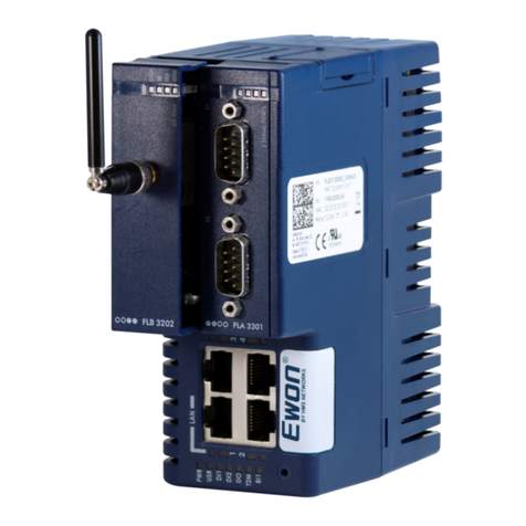
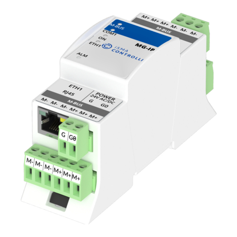
eWON Flexy 205 Owner's manual

Flexy 205
REFERENCE GUIDE
RG-0008-00-EN 1.1 ENGLISH

Important User Information
Liability
Every care has been taken in the preparation of this document. Please inform HMS Industrial Networks SA of any
inaccuracies or omissions. The data and illustrations found in this document are not binding. We, HMS Industrial
Networks SA, reserve the right to modify our products in line with our policy of continuous product development.
The information in this document is subject to change without notice and should not be considered as a commit-
ment by HMS Industrial Networks SA. HMS Industrial Networks SA assumes no responsibility for any errors that
may appear in this document.
There are many applications of this product. Those responsible for the use of this device must ensure that all the
necessary steps have been taken to verify that the applications meet all performance and safety requirements in-
cluding any applicable laws, regulations, codes, and standards.
HMS Industrial Networks SA will under no circumstances assume liability or responsibility for any problems that
may arise as a result from the use of undocumented features, timing, or functional side effects found outside the
documented scope of this product. The effects caused by any direct or indirect use of such aspects of the product
are undefined, and may include e.g. compatibility issues and stability issues.
The examples and illustrations in this document are included solely for illustrative purposes. Because of the many
variables and requirements associated with any particular implementation, HMS Industrial Networks SA cannot as-
sume responsibility for actual use based on these examples and illustrations.
Intellectual Property Rights
HMS Industrial Networks SA has intellectual property rights relating to technology embodied in the product de-
scribed in this document. These intellectual property rights may include patents and pending patent applications in
the USA and other countries.
Flexy 205 Reference Guide RG-0008-00-EN 1.1

Flexy 205 Reference Guide RG-0008-00-EN 1.1
1 Preface ............................................................................................................................... 3
1.1 About This Document.....................................................................................................3
1.2 Document history...........................................................................................................3
1.3 Related Documents .......................................................................................................3
1.4 Trademark Information ...................................................................................................3
2 First Access...................................................................................................................... 4
2.1 Login ............................................................................................................................4
2.2 Language Selection .......................................................................................................4
2.3 Wizards.........................................................................................................................4
3 General Overview............................................................................................................ 6
4 Home Section................................................................................................................... 7
5 Tags Section ..................................................................................................................... 9
5.1 Values...........................................................................................................................9
5.1.1 “View” Mode..........................................................................................................9
5.1.2 “Setup” Mode....................................................................................................... 11
5.2 Alarms ........................................................................................................................16
5.2.1 Summary............................................................................................................ 16
5.2.2 History ............................................................................................................... 16
6 Diagnostic ....................................................................................................................... 18
6.1 Logs ...........................................................................................................................18
6.1.1 Event Logs.......................................................................................................... 18
6.1.2 Realtime Logs...................................................................................................... 18
6.1.3 Scheduled Actions ................................................................................................ 19
6.2 Status .........................................................................................................................19
6.2.1 System Counters .................................................................................................. 20
6.2.2 I/O Servers Counters............................................................................................. 21
6.2.3 System Info......................................................................................................... 25
6.3 Files Transfer ..............................................................................................................26
7 Setup ................................................................................................................................ 28
7.1 Wizards.......................................................................................................................28
7.1.1 System............................................................................................................... 28
7.1.2 Internet............................................................................................................... 29
7.1.3 VPN................................................................................................................... 30
7.1.4 Gateway............................................................................................................. 31
7.2 BASIC IDE ..................................................................................................................32
7.3 Users..........................................................................................................................33
7.3.1 Creation or Modification of a User ............................................................................ 34
7.4 System........................................................................................................................35

Flexy 205 Reference Guide RG-0008-00-EN 1.1
Table of Contents
7.4.1 Main .................................................................................................................. 35
7.4.2 Communication .................................................................................................... 46
7.4.3 Storage .............................................................................................................. 63
7.5 Reboot........................................................................................................................66
A SMS Recipient(s) Syntax............................................................................................. 67
A.1 Syntax ........................................................................................................................67
A.1.1 Message Service Center ........................................................................................ 69
B Configurable Fields for Email and SMS .................................................................. 70

Preface 3 (72)
1 Preface
1.1 About This Document
This document describes all configuration parameters of the eWON Flexy 205.
For additional related documentation and file downloads, please visit www.ewon.biz/support.
1.2 Document history
Version Date Description
1.0 2018-01-12 First release
1.1 2018-05-03 ADDED: WAN Fallback
1.3 Related Documents
Document Author Document ID
Tag Quality eWON CTS KB-0039-00
Set up the LAN IP address of an eWON device eWON CTS KB-0064-00
Flexy & Cosy 131 – WAN Fallback eWON CTS KB-1503-00
Programming Reference Guide eWON CTS RG-0006-01
IO Servers eWON CTS RG-0007-00
Export Block Descriptor eWON CTS RG-0009-00
1.4 Trademark Information
eWON®is a registered trademark of HMS Industrial Networks SA. All other trademarks men-
tioned in this document are the property of their respective holders.
Flexy 205 Reference Guide RG-0008-00-EN 1.1

First Access 4 (72)
2 First Access
To display the web interface of the eWON Flexy 205, open a web browser and target the IP ad-
dress of the device which by default is 10.0.0.53.
If the IP address must be changed, follow the Set up the LAN IP address of an eWON device
document from the Related Documents, p. 3
2.1 Login
The first screen displayed is a login form. The factory predefined parameters to log in to the de-
vice are:
eWON Default Credentials
IP address 10.0.0.53
Login (case insensitive) adm
Password (case sensitive) adm
For security reasons, the password must be changed on first connection! This one
can be changed by going to Setup > Users.
2.2 Language Selection
On first login, a windows appears and asks for the language of the interface: English, French,
German or Italian.
This selection will also be asked after a reset level 2 which refers to a reset factory
configuration.
To change the language of the web interface without performing a reset level 2, the Language
parameter of the comcfg.txt file must be changed. To change it, go to Setup > System > Storage
> Tabular Edition > Edit COM cfg. This method will change only the interface. If the messages
from the event log should also reflect the language change then a reboot is necessary. A reboot
can be done either by power off / on the device or by going to Setup > Reboot.
2.3 Wizards
The next step is the configuration of the Flexy 205.
After the login and the selection of the language, the device will propose to follow the wizards to
configure the System, the Internet connection, the VPN connection and the Gateway.
The wizards are an easy, automatic and straightforward way of configuring the Flexy 205. It is
not mandatory to follow the wizards as the configuration of the Flexy 205 can also be set man-
ually through the config.txt and comcfg.txt files.
A summary of each wizard is explained here under:
System Wizard
User Setup Configuration of the administrator user and the basic setting of the Flexy 205.
Possibility to reset all system related fields to factory settings
Date & Time Configuration of the date and time of the Flexy 205.
Possibility to enable the NTP server.
Flexy 205 Reference Guide RG-0008-00-EN 1.1

First Access 5 (72)
Internet Connection Wizard
Internet Connection Selection of the WAN interface.
Possibility to reset all Internet related fields to factory settings.
WAN Connection Configuration of the WAN interface (IP address, DNS, proxy).
Validate the Internet
Connection
Test the WAN configuration.
VPN Connection Wizard
Talk2M
Configuration
Link the Flexy 205 to a Talk2M account.
Possibility to test of the Talk2M connection.
eFive Configuration Link the Flexy 205 to an eFive.
Possibility to test the custom VPN connection.
Gateway Wizard
PLC Gateway
Configuration
Configuration of the IO port & server.
This wizard is shown only if a COM extension card (serial or MPI) in inserted in the
Flexy 205.
Flexy 205 Reference Guide RG-0008-00-EN 1.1

General Overview 6 (72)
3 General Overview
The web interface is declined in four parts:
Fig. 1 General Overview of the Web Interface
Parts of the Web Interface
Part #1 The header which always stays visible at the top of the interface. The information is
always the same regardless the page displayed.
Several elements are represented:
• Logo of the Flexy 205.
• Breadcrumb: path in the menu of the current view.
• The current user.
• A link to the support web page.
• A link to log out.
• A link to run the wizards.
Part #2 The menu to configure, monitor, ... the Flexy 205.
Displayed as one or two columns depending the section.
Part #3 The actual content of the page.
Part #4 The footer which is always visible at the bottom of the interface.
The information is always the same regardless the page displayed.
Several elements are represented:
• Name of the Flexy 205.
• Version of the firmware.
• Serial number of the Flexy 205.
• Current time of the Flexy 205.
• Status of the Internet and VPN connection.
Flexy 205 Reference Guide RG-0008-00-EN 1.1

Home Section 7 (72)
4 Home Section
If it is not the first time access (check First Access, p. 4) or a reset level 2 hasn’t been per-
formed, the “Home” section is the screen displayed after the login form when users connect to
the web interface of the Flexy 205.
The summary of Flexy 205 status show the following information:
Internet Connection
Fallback The status of the WAN fallback feature.
For more information about the WAN fallback, check the Internet, p. 29.
Internet Status This field appears only if the Internet connection of the Flexy 205 hasn’t been
configured.
Connected since Elapsed time since the Flexy 205 is connected to the Internet.
This field doesn’t appear if the Internet connection hasn’t been configured.
WAN IP Address IP address of the WAN connection.
This field doesn’t appear if the Internet connection hasn’t been configured.
Connected interface WAN interface used to connect the Flexy 205 to the Internet.
This field doesn’t appear if the Internet connection hasn’t been configured.
WiFi Status The SSID of the the Wi-Fi network the Flexy 205 is currently connected to.
This field appears only if the Flexy 205 is equipped with a Wi-Fi interface.
GSM Status The name of the cellular operator, the signal strength and the cellular technology
used.
This field appears only if the Flexy 205 is equipped with a cellular interface.
GSM data
consumption
The cellular consumption of the Flexy 205 (upload & download).
This field appears only if the Flexy 205 is equipped with a cellular interface.
VPN Connection
Status This field appears only if the VPN connection of the Flexy 205 hasn’t been
configured.
Connected since Elapsed time since the Flexy 205 is connected to the VPN service.
This field doesn’t appear if the VPN connection hasn’t been configured.
VPN IP Address IP address of the VPN connection.
This field doesn’t appear if the VPN connection hasn’t been configured.
System Information
Current user The user used to browser the web interface.
eWON Type The model of the device.
Serial Number The serial number of the device.
Firmware Version The current firmware version of the device.
Current time The current time of the device.
LAN IP/Mask The LAN IP address and subnet mask of the device.
By default: 10.0.0.53/255.255.255.0
Modem Type The type of modem inserted in the Flexy 205.
Free Config Memory The memory left for configuration.
Flexy 205 Reference Guide RG-0008-00-EN 1.1

Home Section 8 (72)
Free Program
Memory
The memory left for scripting.
Extension Cards The name/type of extension card(s) inserted in the Flexy 205.
If none, this section doesn’t appear at all.
This is a proof of recognition, not that the extension card(s) is currently being used.
Gateway Status
NAT 1:1 Status of the NAT 1:1
Possibility to change this status by clicking on it.
Flexy 205 Reference Guide RG-0008-00-EN 1.1

Tags Section 9 (72)
5 Tags Section
The “Tags” section contains 3 sub-sections:
• Values: configuration & monitoring of the real-time values of the tags.
• Alarms: monitoring of the tag alarms and checking the history of those alarms.
• IO Servers: configuration of the IO server(s) plugged in the Flexy 205.
All 3 sub-sections are described in the following chapters.
5.1 Values
The Flexy 205 monitors and manages variables called tags which are produced by IO servers.
The configuration of a tag defines its IO server and all its monitoring parameters such as alarm
levels, historical logging...
The “Value” section is the area listing the tags and their values for monitoring but also configura-
tion purposes.
The switch between monitoring and configuring is done via the “Mode” button in the upper left
side of the page:
• Mode “View”: this is the monitoring view.
• Mode “Setup”: this is the configuration view.
5.1.1 “View” Mode
This mode which is the monitoring panel displays different types of information:
Tags displayed as “View”
Pages Allows the filtering of the tags based on the page they are linked to.
By default: All, Default and System.
Tag Groups Allows the filtering of the tags based on the group they belong to.
Filter Allows the filtering of the tags based on their name.
Refresh button Allows the refresh of the list.
Edit Value Change manually the value of a tag. This can also be done by double-clicking the
value of the tag.
Realtime Graph Shows a graph with the current values of the tag.
This button is shown only if a tag is configured to log real-time value.
Historical Logging
button
Check the log of the tags which have the historical logging enabled.
Historical Graph Shows a graphic of the tag values in a determined time interval.
This button is shown only if a tag is configured to log historical data.
Alarms Indicates if the alarm is set for the tag. By clicking on the icon, a redirection to the
Alarm summary page is performed (check Summary, p. 16).
Historical Logging
Table
Indicates if the historical logging is set for the tag.
Real-time Logging Indicates if the real-time logging is set for the tag.
Name Indicates the name of the tag.
Status / Quality Indicates how reliable and recent the tag value is.
Flexy 205 Reference Guide RG-0008-00-EN 1.1

Tags Section 10 (72)
More details in the Tag Quality document from the Related Documents, p. 3.
Value Indicates the current value of the tag. This value can be modified by double-clicking
on it.
Tag Description Indicates the description of the tag.
Autorefresh Indicates if the tags should be refresh automatically and on which time interval.
5.1.1.1 Real-time Graph
This area shows the real-time value of the selected tags as a graphic. This section appears only
if a or some tags have been previously selected.
5.1.1.2 Historical Logging Table
This area shows the recorded values of the selected tags as a table where columns are the tag
names and rows are the recorded timestamp with the corresponding values.
This table can be retrieved by viewing this section or by using the Export Block Descriptor
(check the Export Block Descriptor from the Related Documents, p. 3.)
Parameters of the Historical Logging Table
From ... To .... The time frame for which the user wishes to display the logs of the selected tags.
Interval The time frame division for the graphic.
Groups Filter by group of tags
Include tags with HL
disabled
Include tags that don’t have historical logging activated but have previous logged
data.
The historical logging table is linked to the IRCALL.BIN file. This one is an incremental record-
ing of the logged data.
5.1.1.3 Historical Graph
This area shows the recorded values of the selected tags as a graphic. This section appears on-
ly if a or some tags have been previously selected.
Parameters of the Historical Graph
From ... To ... The time frame for which the user wishes to display the logs of the selected tags.
Flexy 205 Reference Guide RG-0008-00-EN 1.1

Tags Section 11 (72)
5.1.2 “Setup” Mode
This mode which is the configuration panel displays different types of information:
Tags displayed as “Setup”
Pages Allows the filtering of the tags based on the page they are linked to. Possibility to
add another page to the list or delete one existing (right-click).
By default: All, Default and System.
Check Creation of a Page, p. 12.
Tag Groups Allows the filtering of the tags based on the group they belong to.
Filter Allows the filtering of the tags based on their name.
Refresh button Allows the refresh of the list.
Add button Add a new tag and configure it. If a tag is selected, the “Add” can become “Add as
selected”.
Check Creation or Modification of a Tag, p. 12.
Edit Edit the tag settings.
This button is displayed only if a tag is selected.
Delete Delete a tag.
This button is displayed only if a tag is selected.
Configure Alarm
actions
Set the parameters of a tag alarm.
This button is displayed only if a tag is selected.
Historical Logging
button
Check the log of the tags which have the historical logging enabled.
Alarms Configure the actions the Flexy 205 should perform when alarm is reached.
Historical Logging Indicates if the historical logging is set for the tag.
Real-time Logging Indicates if the real-time logging is set for the tag.
Name Edit the settings of the tag.
Type Indicates the nature of the tag
IO Server Indicates which IO server is linked to the tag.
Topic Indicates which topic is set to the tag.
Possible values for MEM tag:
• [empty]
• RET(entive): value will be remembered on reboot.
Possible values for eWON tag:
• [empty]
• SYS(tem): access to some of the system information.
Possible values for IO Server tag: A, B or C
IO Address Address of the tag linking the Flexy 205 and the third-party device.
Status / Quality Indicates how reliable and recent the tag value is.
More details in the Tag Quality document from the Related Documents, p. 3.
Value Indicates the current value of the tag.
Tag Description Indicates the description of the tag.
Autorefresh Indicates if the tags should be refreshed automatically and on which time interval.
Flexy 205 Reference Guide RG-0008-00-EN 1.1

Tags Section 12 (72)
5.1.2.1 Creation of a Page
Page definitions are used in the Flexy 205 for two purposes:
• Restrict user rights to specific directories in the user defined web site.
• Organize tags in pages to ease viewing and restrict user access to specific tags.
A total of 10 user pages can be created.
When tags are defined in a specific page and the name of that page is modified, the same set
of tags will belong to the renamed page and users allowed to see the former page will automati-
cally see the renamed one.
If a page is deleted while containing tags, those ones will return to the default page. All the
users who had access to that page only will have access to “Default” page.
Any text can be entered for the page name but if a page name is used for directory restriction, it
must comply with the directory syntax.
5.1.2.2 Creation or Modification of a Tag
When creating a tag, multiple fields must be provided:
Tag Parameters: Identification
Tag Name The name of the tag
It will be used for any reference to the tag when using the export or script function.
It will also be included in the alarm email / SMS.
It cannot contain: spaces, “$” (dollar) character or “"” (quote) character.
It shouldn’t contain “-” (minus) character if destined to be used in scripting.
The maximum length for is limited to 64 characters.
Page Allows the filtering of the tags and display them on a specific page
The basic configuration offers choices between “Default page” or “System page”.
Customer pages can be created an will be automatically added to this list.
Tag Description A free text to describe the meaning of the tag.
This Information is included in the email sent on alarm.
Tag Parameters: I/O Server Setup
Server Name The IO server name is the data source of the tag name. Six data sources are
available: MEM (virtual IO used by script function), eWON (eWON internal IO),
MODBUS, NETMPI, SNMP, DF1, FINS, ABLOGIX, S73&400, S7200, HITACHI,
MELSEC and BACNET.
For details, refer to theIO Servers document from the Related Documents, p. 3.
Topic Name It is used to apply a common configuration to several tags.
Topic names are configured in the IO Servers (check IO Servers document from
Related Documents, p. 3).
Address This indicates the complete address syntax (path) required to reach the register
inside the third-party device.
To ease the writing of the polling destination, a Tag Helper is available and appears
automatically as soon as text is typed in the field.
Type Defines the nature of the tag:
• Automatic: let’s the Flexy 205 decide the best nature of the tag. The decision
depends on the IO server register / modifier type.
Flexy 205 Reference Guide RG-0008-00-EN 1.1

Tags Section 13 (72)
• Floating Point: a single precision float precision format (IEEE float
representation).
• Boolean: a binary value.
• Integer: a 32-bit signed integer.
• DWord: a 32-bit unsigned integer.
Force Read Only Allows the disabling of the “Update” function in the “View” mode of the “Values”
section.
The tag is still read/write for BASIC scripting.
eWON value Defines the offset and scale factor to be applied to the IO value coming from the
third-party device. The offset and scales are float values. The negative values are
accepted.
The tag value will be: TAGval = IOSERVERval * scale + offset.
Tag Parameters: Alarm Setup
Alarm Setup If enabled, the alarm will be generated.
Alarm Level Low Low “warning” threshold value for alarm detection.
Alarm Level High High “warning” threshold value for alarm detection.
Alarm Level LowLow Low “danger” threshold value for alarm detection.
Alarm Level HighHigh High “danger” threshold value for alarm detection.
Value Deadband The deadband is the difference between the alarm level and the RTN level (Return
To Normal).
E.g.: if the alarm value is 20°C with a deadband set to 1, the alarm is triggered
when the temperature crosses this 20°C boundary. On the other hand, the alarm
status will be RTN when the temperature passes below 19°C (because 20° - 1).
Boolean Alarm Level The alarm value of a boolean tag name. This is not applicable for analog tag name.
Activation Delay The time in seconds for which the tag has to be out of threshold before the alarm
tag is triggered.
Auto acknowledge on
RTN
If checked, the alarm will be automatically acknowledged when the alarm state
goes to RTN. Thus, the alarm is directly ended.
Alarm Hint The information related to the alarm action. This Information will be included in the
alarm email.
Tag Parameters: Historical Logging
Historical Logging If enabled, the values of the tag will be logged in a circular file.
This is a non-volatile logging. The data is stored in the flash file system. All the data
is stored in the same file, the maximum number of values that can be saved is from
16384 to 139264, depending on the resources storage setup of the Flexy 205.
When maximum size is reached, the oldest data will be erased first.
Logging Deadband Defines the deadband of the incremental recording of the tag. Setting a negative
value will disable it.
Logging Interval Defines the interval, in seconds, for the tag recording. Setting 0will disable it.
Can be used at the same time as logging deadband.
Flexy 205 Reference Guide RG-0008-00-EN 1.1

Tags Section 14 (72)
Tag Parameters: Real-time Logging
Real-time Logging If enabled, the values of the tag will be logged in memory.
Real-time logging is different than historical logging because the data is saved in a
circular memory buffer. The other difference is that incremental recording is not
possible, only fixed interval recording can be performed.
Time Span Defines the total logging window time in seconds.
Logging Interval Defines the interval, in seconds, of the tag recording.
Tag Parameters: Tag Visibility
Published Value The value published by the Flexy 205 could be the same as the tag value or could
be modified with a scale factor and an offset.
Modbus TCP visibility If enabled, the tag will be visible.
Each tag in the Flexy 205 can be accessed through a Modbus TCP master.
Register The address of the register, starting with 1.
Only the register address has to be specified, the type of tag (coil, contact, input
register or holding register) is obtained from the tag type (analog or boolean) and
the tag read-only or read/write property (obtained from the IO server).
Use 32-bit format If checked then 2 consecutive 16 bits registers will be reserved and the value will
be an output as a 4 bytes IEEE float in those 2 registers (standard Modbus float
representation).
If the tag is published as integer it may need to be scaled to fit the 16 bits Modbus
register. This operation will be applied to the tag value before publishing it.
SNMP visibility If enabled, the tag can be seen by the SNMP manager.
OID The base OID is already defined, the only parameter is the last part of the OID.
Tag groups Allows the grouping of tags into group (from A to D).
5.1.2.3 Configuration of an Alarm Tag
The configuration of an alarm for a specific tag can be done either by clicking on the “Configure
Alarm actions” button (when a tag has been selected) or on the alarm icon located in the tag
row.
Send an Email
Email upon Checks the alarm states triggering an email (ALM, ACK, RTN, END).
Format as short
message
In some cases, it is useful to have the whole message sent in the subject field.
For example: if the email should be routed as an SMS.
Email to The list of “TO” email address(es). They must be seperated by “,” (comma) or “;”
semi-colon.
Email CC The list of “CC” email address(es). They must be seperated by “,” (comma) or “;”
semi-colon.
Flexy 205 Reference Guide RG-0008-00-EN 1.1

Tags Section 15 (72)
Email Subject The subject of the email (except if short message is selected).
Email Attachment(s) The body text of the email.
This text can include Export Block Descriptors inline (as text) or as attachment files.
There can be as many attachments as required.
Attachments to include in the email must follow the syntax: &[EBD_1] &[EBD_2]
For example: &[$dtRTGA_AN01$ftG] &[$dtEV$ftT] will export real time data of
“GA_AN01” tag as a graphic and the event log file as a text file.
Send an SMS
SMS upon Checks the alarm states triggering an email (ALM, ACK, RTN, END).
SMS Destination The list of SMS recipient(s).
See SMS Recipient(s) Syntax, p. 67.
SMS Subject The content appearing at the beginning of the SMS message.
Transfer to FTP
Put FTP upon Checks the alarm states triggering an email (ALM, ACK, RTN, END).
Destination File Name The name of the file to create on the distant FTP server. The name can contain
path specification.
File Content The file content can be static or dynamic.
If a standard (static) text is put in this field, the file that will be transferred will
receive that static text as content.
If the file content has the following form, one (or more) file will be written with a
dynamic content: [EXPORT_BLOC_DESCRIPTOR_1] [EBD_2]...The number of
EBD is unlimited.
If the “$fn” field is used with multiple EBD, the “Destination File Name” property
must be empty.
Transfer to SNMP
SNMP Trap upon Checks the alarm states triggering an email (ALM, ACK, RTN, END).
Trap Subject The specific text displayed in the trap event of the SNMP manager.
The text string is limited to 256 chars. Traps are sent to all the hosts defined in the
SNMP configuration web page configured to receive such traps.
The information sent in the SNMP trap on alarm trigger is the following:
Parameter Definition Composition
Param 0 The tag name. Text [0...63]
Param 1 The alarm message based on the
“trap subject” defined here above.
Text [0...63]
Param 2 The value of the tag in alarm mode. Integer [32bits]
Param 3 The alarm status. Integer
Param 4 The alarm type Integer
Flexy 205 Reference Guide RG-0008-00-EN 1.1

Tags Section 16 (72)
5.2 Alarms
The “Alarms” section proposes two sub-sections:
• Summary: the real-time alarm of a tag. It represents the current status of an alarm for a tag.
• History: the log of all alarm actions. It shows a table of all alarm status for a tag.
5.2.1 Summary
This is the real-time alarm page listing all tag names currently in alarm state.
Summary of Current Tag Alarms
Filter Allows the filtering of the table based on the name of tags.
Acknowledge
selection
Allows the acknowledgement of an alarm.
This is available only if a tag alarm is selected.
Date The time & day of the Flexy 205 when the alarm has been triggered.
Name The name of the tag.
If an “Alarm hint” has been set in the tag configuration, it will be shown near its
name.
Action / Date The status of the tag alarm at a specific time.
UserAck The name of the user who acknowledged the alarm.
Description The description of the tag in alarm mode.
Types of Alarm
ALM (HI) The tag is in alarm mode. The current value is in warning high position.
ALM (HIHI) The tag is in alarm mode. The current value is in insecure high position.
ALM (LO) The tag is in alarm mode. The current value is in warning low position.
ALM (LOLO) The tag is in alarm mode. The current value is in insecure low position.
ALM The (boolean) tag is in alarm mode. The current value is out of defined threshold.
RTN The tag returns to normal status. The current value has been previously outside the
defined threshold and hasn’t been acknowledge but is now inside the threshold.
ACK The tag has been acknowledged. The current value is outside the defined threshold
but a user has acknowledge the tag alarm.
5.2.2 History
The historical alarm screen is used to find the alarms generated in the past and know who ac-
knowledged them. All the alarms are stacked from the top to the bottom.
Summary of Historical Tag Alarms
Filter Allows the filtering of the table based on the name of tags.
Items to display The number of items to show on the current page. All other items will be hidden.
Date The time & day of the Flexy 205 when the alarm has been triggered.
Name The name of the tag.
Status The status (ALM, RTN, ACK pr END) of the tag alarm at a specific time.
Flexy 205 Reference Guide RG-0008-00-EN 1.1

Tags Section 17 (72)
Type The type (LOLO, LO, HI, HIHI) of the tag alarm at a specific time.
UserAck The name of the user who acknowledged the alarm.
Description The description of the tag in alarm mode.
Flexy 205 Reference Guide RG-0008-00-EN 1.1

Diagnostic 18 (72)
6 Diagnostic
The “Diagnostic” area is the place to go if an issue is encountered on the Flexy 205. This sec-
tion is divided in 3:
• Logs: regroups all the logs the Flexy 205 records.
• Status: regroups all the information of the current state of the Flexy 205.
• Files Transfer: allows the possibility to display / download several configuration / communi-
cations files of the Flexy 205.
6.1 Logs
The “Logs” section is the place where all recorded events can be displayed. It is divided in 3
sub-sections: Event Logs, Realtime Logs and Scheduled Actions.
6.1.1 Event Logs
This page displays the information recorded in the “Events.txt” file (check Files Transfer, p. 26).
On this page, the logged data are presented in reverse chronological order: recent events on
the top, older ones at the bottom). The events are displayed in different colors to differentiate
Error (red), Warning (orange) and Trace (black) events.
Event Logs Page Parameters
Filter Allows the filtering of the data. All 4 columns are taken into consideration.
Items to display Allows the display of a limited number of items.
Class Allows the filtering of the events based on their nature / category.
Level Allows the filtering of the events based on their severity. The chosen level and the
level(s) greater than this level are shown.
Time The time & date when the event occurred.
Event The ID of the event.
Description The description of the event. Each description refers to a single event ID.
Originator The interface that triggered an event log.
Autorefresh If enabled, the list will be automatically refreshed at the defined time interval.
6.1.2 Realtime Logs
This page displays the debug information for different interfaces.
These logs are stored in RAM memory and are cleared on reboot.
This logging is a time consuming task and thus will slow down the overall behavior
of the Flexy 205. These debug interfaces should be activated and used only during
the debugging process!
Flexy 205 Reference Guide RG-0008-00-EN 1.1
Other manuals for Flexy 205
2
Table of contents
Other eWON Gateway manuals
Popular Gateway manuals by other brands

Winmate
Winmate EAC Mini EACIEK20 user manual
Moxa Technologies
Moxa Technologies UC-8580 Series Quick installation guide
Dension
Dension ice Link Gateway 100 user manual
RTA
RTA 460BSUS-N2EW Product user guide
Actisense
Actisense NMEA NGW-1-ISO Installation and user manual
Veeder-Root
Veeder-Root ProtoNode FPC-N54 Startup guide
