Excel Technology LTM-2000 Specification sheet

ETC_PUGM_LTM2K_v1.0
PRODUCT USER GUIDE
LTM-2000
IN-PAVEMENT LOOP TEST METER

LTM-2000 Disclaimer
ETC_PUGM_LTM2K_v1.0
1DISCLAIMER
Excel Technology Co Pty Ltd (ETC) reserves the right to make changes to the technology described in this
document without notice and advises its clients to obtain the latest version of the relevant information
prior to placing an order. Excel Technology Co Pty Ltd warrants its products to the specification detailed
herein in accordance with standard conditions of sale, client specification, and conditions imposed
through government legislation, and is not liable for functional performance, operational performance,
or any damage consequential or otherwise resulting from the use of the ETC product.
Testing and product control techniques are utilised to the extent that Excel Technology Co Pty Ltd deems
necessary to support the relevant specification and warranty. Excel Technology Co Pty Ltd acknowledges
the proprietary information provided by Third Party component suppliers however, Excel Technology Co
Pty Ltd assumes no responsibility for the use of any other circuit or device other than the circuitry
embodied on Excel Technology Co Pty Ltd numbered engineering drawings and on Excel Technology Co
Pty Ltd circuit cards as identified according to the requirements of the Circuit Layouts Act 1989
(Australia) and used in accordance with the relevant equipment instructions contained herein.
Excel Technology Co Pty Ltd grants the user/client rights to reproduce any of the documents contained
herein but not subject to conditions of ‘Non-Disclosure’, providing such reproduction is conducted with
no alteration to any material written, drawn, or otherwise reproduced and/or contained in this
document.
Excel Technology Co and the Excel Technology Co logo are trademarks of Excel Technology Co Pty Ltd.
Copyright © Excel Technology Co (ETC) Pty Ltd 2021.

LTM-2000 Warning
ETC_PUGM_LTM2K_v1.0 1
2WARNING
Extreme caution is required when handling this device. The insulation breakdown functionality is a
controlled Megger test in which 500 Vdc is applied to the RED and BLACK output terminals for a short
period of time (approximately 200 ms).
Ensure loop under test are disconnected from any voltage source and are de-energised before
connecting the leads of the Loop Test Meter.
Consult the User Manual before activating functions on the device with the following symbol:
There is a risk of electric shock while the Insulation Test is active. During this test, between 400 Vdc
and 600 Vdc is applied to the RED and BLACK loop terminals to measure the loop insulation
resistance in Megaohms.
•While test is active do not touch the RED or BLACK leads or any conductive surfaces
electrically connected to the RED or BLACK test leads
•Do not connect the RED or BLACK terminal leads to any sensitive electronic equipment
during the insulation test as it may damage the equipment.
3CONTACT EXCEL TECHNOLOGY CO
Email: enquiries@exceltech.com.au
Website: www.exceltech.com.au
Phone: +61 7 3279 4322
Address: 18 Staple Street
Seventeen Mile Rocks
Queensland, AUSTRALIA 4073

LTM-2000 Contact Excel Technology Co
ETC_PUGM_LTM2K_v1.0 2
4CONTENTS
1DISCLAIMER.............................................................................................................................................. I
2WARNING................................................................................................................................................ 1
3CONTACT EXCEL TECHNOLOGY CO........................................................................................................... 1
5LTM-2000 IN-PAVEMENT LOOP TESTER ................................................................................................... 3
5.1 TERMINALS................................................................................................................................................ 4
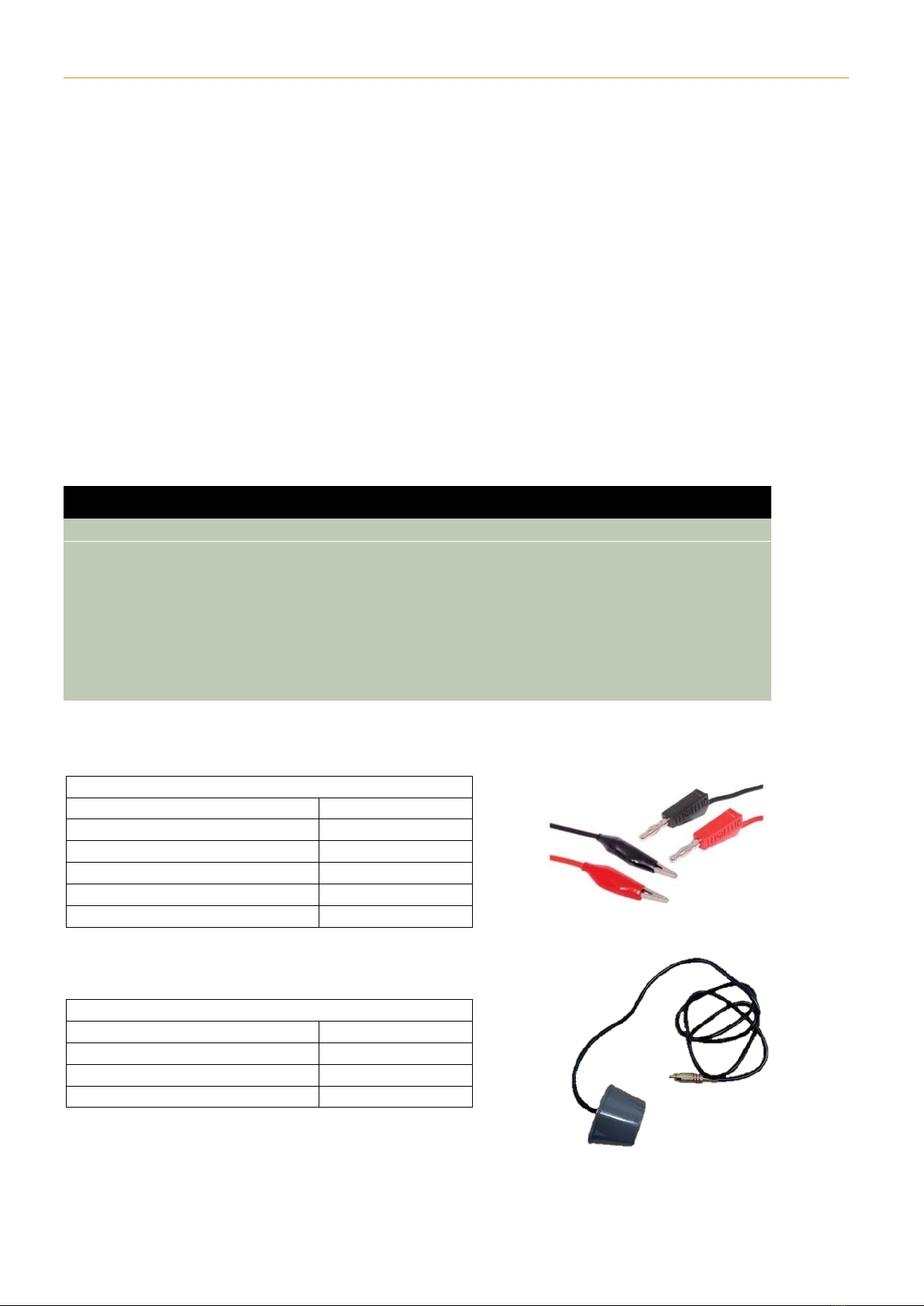
5.2 INCLUDED CABLES....................................................................................................................................... 4
5.2.1 Red and Black Test Leads................................................................................................................... 4
............................................................................................................................................................................ 4
5.2.2 Excel Technology Co. Loop Finder Probe............................................................................................ 4
6USAGE ..................................................................................................................................................... 5
6.1 POWER..................................................................................................................................................... 5
6.1.1 Turn On Device .................................................................................................................................. 5
6.1.2 Turn Off Device .................................................................................................................................. 5
6.1.3 Automatic Time-Out Shut-Down ....................................................................................................... 5
6.1.4 Critical Battery Shut-Down after Start-Up......................................................................................... 5
6.1.5 Critical Battery Shut-Down Before Start Up ...................................................................................... 6
6.1.6 Toggle Backlight ................................................................................................................................ 6
6.1.7 Backlight Time-out............................................................................................................................. 6
6.2 CHARGING................................................................................................................................................. 6
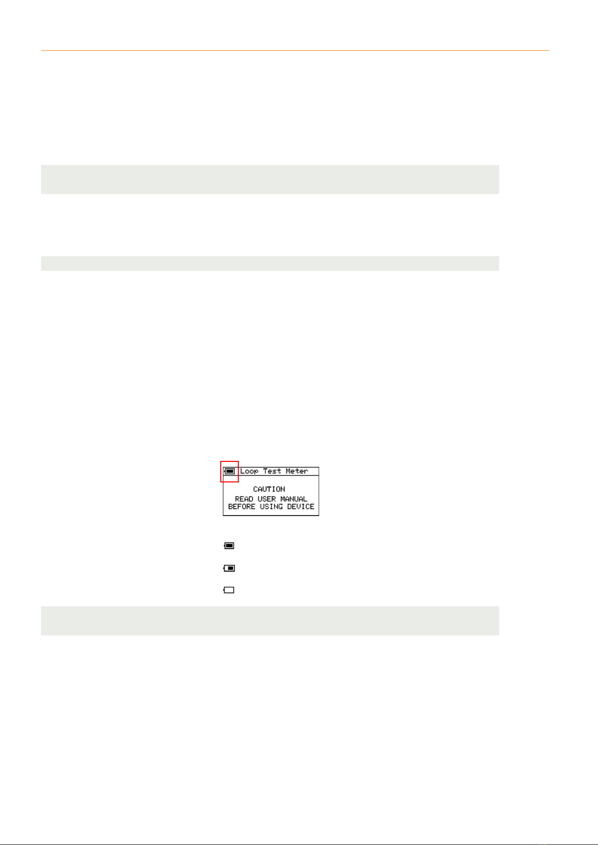
6.2.1 Battery Indicator................................................................................................................................ 6
6.2.2 USB Charging..................................................................................................................................... 7
6.2.3 Battery LED Indicator......................................................................................................................... 7
6.3 QMETER ................................................................................................................................................ 7
6.3.1 Instructions for Calibrating Lead Resistance ..................................................................................... 9
6.3.2 Instructions for Measuring Loop Characteristics ............................................................................. 10
6.3.3 Status Definitions............................................................................................................................. 11
6.4 INSULATION TEST...................................................................................................................................... 12
6.4.1 Instructions for Evaluating Winding to Earth Insulation Integrity................................................... 12
6.5 LOOP FINDER........................................................................................................................................... 15
6.5.1 Locate In-Pavement Loops By Walking on Road Surface................................................................. 15
6.5.2 Locate Exact Position of Loop Windings .......................................................................................... 17
6.5.3 Locate in-pavement loops from a moving vehicle ........................................................................... 18

LTM-2000 LTM-2000 In-Pavement Loop Tester
ETC_PUGM_LTM2K_v1.0 3
5LTM-2000 IN-PAVEMENT LOOP TESTER
The Loop Test Meter 2000 (LTM-2000) is a second-generation, field service device suitable for in-
pavement loop analysis. The LTM-2000 has three main functionalities for testing in-pavement loops:
1. Q Meter
•Measure in-pavement loop resistance, inductance, device dependant resonance
frequency and loop Q factor
•Time graph showing frequency changes when vehicle passes over loop in the road
•Fast short circuit and open circuit detection
•In field manual lead resistance calibration.
2. 500V Insulation Test
•Loop and feeder cable to earth insulation resistance measuring up to 200 MΩ
•Automatic connection checking for short circuit and incorrect connections to loop.
3. Loop Finder
•Find energised in-pavement loops installed in the road using ETC Loop Finder Probe
•Locate winding position to ±5cm in the road surface
•Locate loop area by sweeping the area with the probe either walking or driving up to
110km/hr
•Audible beep when loop detected.
The LTM-2000 is entirely portable with 30 - 250 hours of battery life using a 2600 mAh rechargeable
Li-ion battery with 5 Vdc 1A Micro-USB charging.
The LTM-2000 features a transflective graphical LCD display with a toggled white backlight for use in
any light conditions.

LTM-2000 LTM-2000 In-Pavement Loop Tester
ETC_PUGM_LTM2K_v1.0 4
5.1 TERMINALS
The LTM-2000 has four input terminals.
1. BLACK banana terminal
•Q Meter: Connect to end of loop or feeder cable
•Insulation Test: Connect to earth
•Loop Finder: Not Required.
2. RED banana terminal
•Q Meter: Connect to end of loop or feeder cable
•Insulation Test: Connect to end of loop or feeder cable
•Loop Finder: Not Required.
3. RCA Loop Finder probe terminal
•Q Meter: Not Required
•Insulation Test: Not Required
•Loop Finder: Connect and dangle probe 0 mm –40 mm from surface.
4. Micro USB 5V charging port.
CAUTION
The LTM-2000 Q Meter and Insulation Test functions are used for testing de-energised in-pavement
inductive loops only.
All terminals have TVS ESD protection up to 30 kV and clamping voltage up to 14.5V. Do not connect
red and black alligator clips to live voltages >5 Vdc for prolonged periods as this may cause damage
to the device.
DISCONNECT THE LOOP UNDER TEST FROM THE VEHICLE DETECTOR SYSTEM BEFORE CONNECTING
ALLIGATOR LEADS.
5.2 INCLUDED CABLES
5.2.1 RED AND BLACK TEST LEADS
RED & BLACK Test Leads
Weight
40 g
Length
1200 mm
Wire connection
Alligator
LTM-2000 plug socket
Banana 4 mm
Lead Resistance
0.2Ω–0.6Ω
Withstanding 500V
< 1 minute
5.2.2 EXCEL TECHNOLOGY CO.LOOP FINDER PROBE
Excel Technology Loop Finder Probe
Weight
320 g
Length
1500 mm
Inductance
1 mH
Plug type
RCA Phono

LTM-2000 Usage
ETC_PUGM_LTM2K_v1.0 5
6USAGE
6.1 POWER
6.1.1 TURN ON DEVICE
To power on the device, short press the RED Power Button.
•The following start-up logo will be displayed for a short period of time:
•The Loop Test Meter start menu will then be displayed with the following warning message:
Note: Holding the Power Button when the device is off will turn the device on for a short period of
time before turning it off again. This feature is to stop the device from accidentally turning on when
the on button is held on.
6.1.2 TURN OFF DEVICE
To turn off the device at any time, press and hold the power button for approximately two seconds.
•The screen will clear to blank,
•2 short beeps will sound,
•The RED STATUS light will illuminate until the device is completely turned off.
6.1.3 AUTOMATIC TIME-OUT SHUT-DOWN
If no buttons are pressed the device will automatically shut down after a set period of approximately
15 minutes.
•The screen will clear,
•2 short beeps will sound,
•The RED STATUS light will illuminate until the device is completely turned off.
6.1.4 CRITICAL BATTERY SHUT-DOWN AFTER START-UP
If the battery voltage of the device reaches a critically low voltage during operation, the device will
automatically turn off.
•The screen will display the following message:
•2 short beeps will sound,
•The RED BATTERY light will illuminate until the device is completely turned off.

LTM-2000 Usage
ETC_PUGM_LTM2K_v1.0 6
6.1.5 CRITICAL BATTERY SHUT-DOWN BEFORE START UP
The device will automatically shut down if the user attempts to turn on the device when the battery
voltage is at or below a critically low level.
•2 short beeps will sound,
•The RED BATTERY light will illuminate until the device is completely off.
Note: If the device does not respond at all to the power button being pressed, the battery may be too
low to activate this sequence and will need to be charged.
6.1.6 TOGGLE BACKLIGHT
The Backlight can be toggled by short pressing the RED Power button when the device is on for use in
low light conditions.
Note: Prolonged use of the backlight will significantly reduce battery life.
6.1.7 BACKLIGHT TIME-OUT
The Backlight will automatically turn off after approximately 5 minutes of inactivity to reduce power
consumption and increase battery life.
6.2 CHARGING
6.2.1 BATTERY INDICATOR
The LTM-2000 features a rechargeable 2600 mAh Li-Ion battery with a working supply voltage
between 3.6 Vdc at minimum discharge level to 4.2 Vdc at maximum charge level.
The battery voltage level is indicated by a battery charge icon in the top left of the display:
Full Battery
50% Battery
Low Battery
Note: The battery icon is a linear approximation of the battery’s remaining charge. Time taken to go
from 100% to 50% charge may not equal time taken to go from 50% to 0% charge.

LTM-2000 Usage
ETC_PUGM_LTM2K_v1.0 7
6.2.2 USB CHARGING
The LTM-2000 can be charged by simply connecting a standard USB power supply via a Micro USB
charging cable to the charging port located at the bottom of the device.
Maximum estimated charging time from absolute minimum discharge 0 mAh to full 2600 mAh is 5
hours.
The charging power can be supplied from any standard USB charger between 4.5 Vdc and 5.5 Vdc.
These include wall chargers, car chargers, computer USB 2.0 or USB 3.0 ports, etc.
Note: The LTM-2000 USB input has inbuilt overvoltage protection up to 20 Vdc, ESD protection ±30
kV, overcurrent limiter of 3A, reverse current limiter of 400 mA. The maximum charging current is 1A.
When the USB is connected to the device the following icon will be displayed instead of the battery
level icon:
USB Charger Connected (4.5 Vdc > USB supply voltage < 5.5 Vdc)
USB Overvoltage Detected (5.5 Vdc > USB supply voltage < 20 Vdc)
6.2.3 BATTERY LED INDICATOR
Colour
Meaning
GREEN
Battery fully charged
YELLOW
Battery charging
RED
Low battery
6.3 Q METER
The Q Meter functionality is used for measuring the following parameters of the vehicle detection in-
pavement loop:
Symbol
Parameter
Typical Range
R
Resistance
0.50 Ω- 3.00 Ω(0.1 ΩMin, 50 ΩMax)
L
Inductance
40 μH - 700 μH
F
Tuned Frequency
15 kHz - 140 kHz
Q
Q-factor
> 6 (*Vehicle classification > 12)
The Q Meter function also features:
•Short Circuit detection (feeder to feeder resistance < 0.1 Ω)
•Open Circuit detection (feeder to feeder resistance > 50 Ω)
•Line graph displaying live vehicle detection monitoring for loop position verification
•Alligator lead resistance calibration.

LTM-2000 Usage
ETC_PUGM_LTM2K_v1.0 8
Loop Vehicle Detection Basics
The loops used for vehicle detection are continuous lengths of wire embedded into the roads
surface. The loop is connected via a feeder cable to the vehicle detector system in a nearby cabinet.
The vehicle detector system powers the loop with an oscillating AC signal which produces a magnetic
field in the loop area. The loop current will oscillate at a resonant frequency which is dependent on
the characteristics of the vehicle detector oscillating circuit as well as the inductance of the loop.
When a vehicle with a large metal surface area, parallel to the loop, passes over the loop area, the
resonant frequency increases as the inductance of the loop is decreased. The larger the surface area
and the closer the metal plane is to the loop, the greater the increase in resonant frequency.
The vehicle detection system will monitor the vacant loop frequency as the base frequency. A vehicle
is detected when the frequency spikes above this base frequency.
Q Factor Basics
The Q-Factor is a unitless parameter that indicates the ratio between the loop’s frequency
dependant impedance and the resistive copper losses of its windings. The ratio is given by the
equation:
Where:
= Quality factor
= Inductive reactance of the loop (Ohms)
= Resonate frequency (Hertz)
= Inductance of the loop (Henries)
= Loop copper resistance (Ohms)

LTM-2000 Usage
ETC_PUGM_LTM2K_v1.0 9
6.3.1 INSTRUCTIONS FOR CALIBRATING LEAD RESISTANCE
The resistance of the loop under test can be measured between 0.10 Ωand 50.00 Ω.
•Resistance of the alligator test leads may be up to 1 Ωand is calibrated during factory testing.
However, this resistance may vary considerably with temperature change or different test
leads
•For accurate resistance readings, it is recommended that the technician ensures the “R”
Resistance value reads “0.00 Ω” (as seen below) when the RED and BLACK alligator test leads
are clipped together.
•If the “R” Resistance value does not read “0.00 Ω” when shorted, the following procedure
can be used to “Zero”the short circuit resistance.
Note: Short circuit resistance calibration will be saved to memory even after a device shut-down. This
procedure is not required every time the device is powered on or between separate loop tests.
Step 1
Turn on the device and navigate to the Q Meter Page.
Step 2
Connect the RED and BLACK test leads to the corresponding banana terminals on the top of the
device.
Step 3
Clip the alligator leads together to short circuit them and hold the Q METER button for 3 seconds
until you hear 3x short beeps and see “ZEROED”as seen below.
Step 4
You should now see the “R” resistance value showing “0.00 Ω” and the “SHORT CIRCUIT” status
displayed. If not, restart the device and try again.

LTM-2000 Usage
ETC_PUGM_LTM2K_v1.0 10
6.3.2 INSTRUCTIONS FOR MEASURING LOOP CHARACTERISTICS
Step 1
Ensure that the loop is de-energised by disconnecting both ends of the loop feeder cable from the
rack. A loop that is still connected to a rack may interfere with loop characteristic measurements.
Note: The terminals on the device are not to be connected to any live voltages. Applying more than
5.0V to the RED and BLACK leads may cause permanent damage to the device.
Step 2
Connect the RED alligator clip to one end of the loop feeder cable and connect the BLACK alligator
clip to the other end of the loop feeder cable.
Note: The loop feeder cables have no polarity.
Step 3
The status will read “LOOP” and the following parameters will be listed:
•“R” Resistance
•“L” Inductance
•“F” Tuned Frequency
•“Q” Q factor
If the Status does not read “LOOP” refer to 6.3.3 for other status definitions.
Step 4
The line graph shows the Tuned Frequency over time of the loop. Metal vehicles travelling over the
loop will cause an increase in the loops Tuned Frequency and a sharp spike in the line graph. The
graph will settle to the minimum frequency sampled. If the graph does not return to zero, short press
the Q Meter button again to reset the graph.
Note: This function can be used to verify the lane position of the loop under test by witnessing
vehicles passing over the loop and a corresponding frequency spike. Large vehicles in adjacent lanes
may cause small spikes.
Vehicle Passing over loop.

LTM-2000 Usage
ETC_PUGM_LTM2K_v1.0 11
6.3.3 STATUS DEFINITIONS
Table 1 –Q Meter Status Definitions
Status
Resistance
Screenshot
Status LED
Resonant
Frequency
Detected
LOOP
Q Meter has detected a loop
with resistance between 0.10
Ωand 50.00 Ωresistance
Green
Yes
OPEN
CIRCUIT
The resistive load between
the RED and BLACK alligator
leads is >50.00 Ω
Yellow
Yes
Red
No
SHORT
CIRCUIT
The resistive load between
the RED and BLACK alligator
leads is greater than -0.10 Ω
and less than 0.10 Ω
Yellow
Yes
Red
No
RE-ZERO
LEADS
The resistive load between
the RED and BLACK alligator
leads is reading a negative
reading below -0.10 Ω
implying a bad calibration.
The lead resistance needs to
be recalibrated.
Yellow
Yes
Red
No
NO-
OSCILLATION
Q Meter has detected a
resistive load between the
RED and BLACK alligator
leads of between 0.10 Ωand
50.00 Ωbut cannot generate
a tuned frequency with the
load due to poor inductive
properties of the load.
Yellow
No

LTM-2000 Usage
ETC_PUGM_LTM2K_v1.0 12
6.4 INSULATION TEST
CAUTION
EXTREME CARE REQUIRED WHEN using the insulation breakdown test function. This is a controlled
voltage ‘Megger’ test where typically 500 Vdc is applied to the RED and BLACK output terminals for a
short, pre-set period while the LTM-2000 monitors the resistance to earth. The test is an automated
sequence, and an indicative measurement of the insulation resistance will be displayed on the LCD
prior to the test completion.
6.4.1 INSTRUCTIONS FOR EVALUATING WINDING TO EARTH INSULATION INTEGRITY
Step 1
Disconnect the loop and feeder from all other energised/de-energised equipment or conductive
material in the cabinet. The high voltage associated with this test may cause significant damage the
sensitive electronic circuitry in the cabinet if not fully disconnected.
Step 2
Connect the RED wire to one end of the loop wire or feeder cable.
Step 3
Connect the BLACK wire to an appropriate Earth connection point.
Step 4
Press the “Insulation Test” button to navigate to the Insulation page on the LTM-2000.

LTM-2000 Usage
ETC_PUGM_LTM2K_v1.0 13
Step 5
The LTM-2000 can check for the following incorrect connections and will not allow the user to initiate
the test until incorrect connections are resolved:
•Short Circuit: If the resistance between the RED and BLACK terminals is < 50 ohms:
Note: Performing the Insulation test on low impedance loads (< 10 MΩ) will NOT damage the device
and will be displayed on the results page as such. This check is in place as a sanity check for the
technician to ensure they have not unintentionally shorted the connections.
•Loop Detected: If the RED and BLACK leads are connected to each end of a loop and the
LTM-2000 detects an oscillating frequency:
NOTE: There are many ways the RED and BLACK test leads can be incorrectly connected that the LTM-
2000 cannot detect. It is the responsibility of the technician to ensure that:
•Both ends of the loop and feeder cables are completely disconnected from any sensitive equipment
•The RED and BLACK test leads are not connected to any live circuits or sensitive equipment
•The technician is not touching any conductive materials in contact with the RED or BLACK Terminals.
Step 6
Press and hold the insulation test button for two seconds and wait for the bar to reach the end of the
screen. This is a safety measure to ensure the high voltage test is not accidentally triggered.
Note: The LTM-2000 will continuously check for conditions in Step 5 and cancel the test if any
connection checks fail.
Step 7
The test sequence will be automatically carried out. The YELLOW status light will illuminate while the
test sequence is running. The LTM-2000 will produce an audible beep tone while high voltage is
applied to the leads and a short double tone once the sequence is complete.

LTM-2000 Usage
ETC_PUGM_LTM2K_v1.0 14
Step 8
The results are displayed on the following screen:
The following are example readings:
Poor Resistance <10 MΩPoor Resistance 10 MΩ
Okay Resistance 100 MΩGood Resistance >200 MΩ
NOTE:
•The Test Voltage is calibrated upon manufacture but may change depending on external factors
such as battery charge and temperature.
•The Insulation Resistance is calculated using a high impedance divider circuit and considers the
variable input Test Voltage.
•The purpose of this test is to provide the technician with a PASS or FAIL insulation integrity status
for the loop and feeder cables. Various road authorities have stated variations in acceptable
winding to earth insulation resistance thresholds.
•Laboratory testing indicates that mutual capacitance resulting from moisture ingress in the cable
and field joints (e.g., wet cables due to rain) will affect readings.
Test Voltage
Insulation Resistance
Log Scale

LTM-2000 Usage
ETC_PUGM_LTM2K_v1.0 15
6.5 LOOP FINDER
The Loop Finder is a function used to detect the oscillating magnetic fields of an energised in-
pavement loop.
The magnetic field generated by the loop induces a detectable AC signal in the probe when it is in the
active area of the loop.
The loop finder can be used to:
•Locate in-pavement loops by walking on the road surface
•Locate in-pavement loops from a moving a vehicle
•Determine the exact location of the windings in the road and the layout of a loop.
Note: The loop finder is not able to detect loops that are not energised and oscillating at a resonant
frequency generated by a vehicle detection system, as no magnetic field will be generated.
6.5.1 LOCATE IN-PAVEMENT LOOPS BY WALKING ON ROAD SURFACE
CAUTION
This method of loop finding requires the operator to walk out on the road surface in the general area
that a loop is located. The operator will be distracted by the LTM-2000 display and may lose
awareness of approaching vehicles. This test is only to be carried out if the operator is in no danger of
moving vehicles. Proper safety precautions must be implemented. Specific safety requirements vary
according to jurisdiction and local OH&S legislation.
Step 1
Plug the probe RCA connector into the “PROBE” terminal located on the top right of the LTM-2000.
Press the “LOOP FINDER” button to navigate to the loop finder page.
Step 2
Hold the probe by the coaxial cable so that it hangs about 50 mm to 100 mm above the surface of
the road.

LTM-2000 Usage
ETC_PUGM_LTM2K_v1.0 16
Step 3
Slowly walk across the area where the loop is likely located.
•The solid black bar graph gives an indication of the magnetic field strength of the loop and
will increase as the probe gets closer to the loop
•A high pitch tone accompanied by the GREEN STATUS LED will alert the operator when they
have entered the loops magnetic field and the Frequency Step Graph will step up as seen
below:
•The resonant frequency detected will also be displayed in kHz. To get an accurate reading of
the resonant frequency, place the probe on the road surface as close to the loop as possible
and where the magnetic field is strongest
NOTE: The resonant frequency of the loop detected using the loop finder may differ from the
resonant frequency found using the Q Meter on the same loop due to changes in oscillating
circuitry in the LTM-2000 Q Meter and vehicle detector equipment.
•A low pitch tone accompanied by the RED STATUS LED will alert the operator when they exit
the loops magnetic field, and the Frequency Step Graph will step down as seen below:
STATUS
STATUS

LTM-2000 Usage
ETC_PUGM_LTM2K_v1.0 17
6.5.2 LOCATE EXACT POSITION OF LOOP WINDINGS
•The signal will dip when the probe is directly over the loop winding wire. At this point the
magnetic field lines of the loops will be parallel to the surface of the road and the probe coils
and therefore no current will be induced in the probe
•From this effect an operator can use the probe to determine the precise location of a loop
•The field of the loop is partially present outside of the loop area. When slowly walking
towards a single loop, the operator will see a step up when entering the field, followed by a
small dip when directly passing over the loop winding. The Step Graph will remain high while
walking from one side of the loop to the other. A similar dip will be present while exiting the
loop
•Once the edges of a loop are detected with the dips, the operator can slowly sweep the
probe over the dip location to determine a more precise location of the loop windings
•The layout of the loop can also be interpreted from the dips in the Frequency Step Graph.
The screenshots below show the Step Graph topology of a “Side by Side” or “Window Loop”
configuration.
Note: It can sometimes be difficult to find dips towards the edges of the loop. If there is no dip, try
slowing down the sweep or hanging the probe closer to the road surface.
Walk Direction
Loop
Walk Direction
Loop
Walk Direction
Loop

LTM-2000 Usage
ETC_PUGM_LTM2K_v1.0 18
6.5.3 LOCATE IN-PAVEMENT LOOPS FROM A MOVING VEHICLE
CAUTION
This method should be performed using both a driver and an observer. The driver should be focused
only on driving the vehicle and should not be distracted by the LTM-2000. The driver should drive in a
safe manner, maintaining lane position and adhering to speed limits. The observer should take note
of where along the road the loop is detected.
•The Loop Finder probe can be used to quickly locate loops on a stretch of road using a vehicle
travelling up to 110 km/hr
•The probe should be suspended from the vehicle such that the probe is <40 cm from the
road surface and has direct line of sight down
•The probe can be hung out the door and the door carefully closed on the cable, avoiding
pinch points that may damage the cable.
•The vehicle must be driven in a way that positions the probe to pass within the boundary
area of the loop to detect the loops magnetic field
•When the vehicle passes over the loop an audible tone will sound from the device.
Table of contents
Other Excel Technology Test Equipment manuals