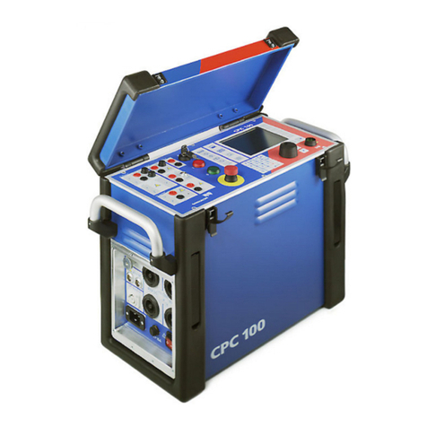
Omicron CPC 100 User manual

CPC 100
Reference Manual
PRIMARY TEST SYSTEM
FOR SUBSTATION EQUIPMENT
COMMISSIONING AND MAINTENANCE
Accessories included

CPC 100 V1.41
Article Number VESD0600 - Manual Version: CPC100.AE.8
With regard to the functionality of the CPC 100 software,
the CPC Explorer and the CPC Editor, this manual refers to the version V 1.41.
© OMICRON electronics 2008
This Reference Manual is a publication of OMICRON electronics GmbH.
All rights including translation reserved. Reproduction of any kind, e.g., photocopying, microfilming or
storage in electronic data processing systems, requires the explicit consent of OMICRON electronics.
Reprinting, wholly or in part, is not permitted.
This Reference Manual represents the technical status at the time of printing. The product information,
specifications, and all technical data contained within this Reference Manual are not contractually
binding. OMICRON electronics reserves the right to make changes at any time to the technology and/or
configuration without announcement. OMICRON electronics is not to be held liable for statements and
declarations given in this Reference Manual. The user is responsible for every application described in
this Reference Manual and its results. OMICRON electronics explicitly exonerates itself from all liability
for mistakes in this manual.
OMICRON electronics translates this manual from its source language English into a number of other
languages. Any translation of this manual is done for local requirements, and in the event of a dispute
between the English and any non-English versions, the English version of this manual shall govern.

i
Contents
Preface . . . . . . . . . . . . . . . . . . . . . . . . . . . . . . . . . . . . . . . . . . . . . . . . . . . . . . . . .1
About this Reference Manual . . . . . . . . . . . . . . . . . . . . . . . . . . . . . . . . . . . . . . . . . . . . . . . . . 1-1
Glossary of Symbols and Terms . . . . . . . . . . . . . . . . . . . . . . . . . . . . . . . . . . . . . . . . . . . . . . . 1-2
Used Symbols . . . . . . . . . . . . . . . . . . . . . . . . . . . . . . . . . . . . . . . . . . . . . . . . . . . . . . . . . .1-2
Used Terms . . . . . . . . . . . . . . . . . . . . . . . . . . . . . . . . . . . . . . . . . . . . . . . . . . . . . . . . . . . . 1-3
Safety Instructions for CPC 100 and its Accessories . . . . . . . . . . . . . . . . . . . . . . . . . . . . . . . 1-5
Principle Use According to Regulations . . . . . . . . . . . . . . . . . . . . . . . . . . . . . . . . . . . . . . . 1-5
Orderly Measures . . . . . . . . . . . . . . . . . . . . . . . . . . . . . . . . . . . . . . . . . . . . . . . . . . . . . . . . 1-5
Operator Qualifications and Primary Responsibilities . . . . . . . . . . . . . . . . . . . . . . . . . . . . 1-6
Safe Operation . . . . . . . . . . . . . . . . . . . . . . . . . . . . . . . . . . . . . . . . . . . . . . . . . . . . . . . . . .1-6
Changing Fuses . . . . . . . . . . . . . . . . . . . . . . . . . . . . . . . . . . . . . . . . . . . . . . . . . . . . . . . . 1-11
CPC 100 in combination with CP TD1. . . . . . . . . . . . . . . . . . . . . . . . . . . . . . . . . . . . . . . . . . 1-12
Designated Use . . . . . . . . . . . . . . . . . . . . . . . . . . . . . . . . . . . . . . . . . . . . . . . . . . . . . . . . . . . 1-13
Functionality of CPC 100 . . . . . . . . . . . . . . . . . . . . . . . . . . . . . . . . . . . . . . . . . . . . . . . . . . . . 1-13
CPC 100 Versions . . . . . . . . . . . . . . . . . . . . . . . . . . . . . . . . . . . . . . . . . . . . . . . . . . . . . . . . .1-15
Introduction . . . . . . . . . . . . . . . . . . . . . . . . . . . . . . . . . . . . . . . . . . . . . . . . . . . . .2
Functional Components of CPC 100 . . . . . . . . . . . . . . . . . . . . . . . . . . . . . . . . . . . . . . . . . . . . 2-2
Front Panel . . . . . . . . . . . . . . . . . . . . . . . . . . . . . . . . . . . . . . . . . . . . . . . . . . . . . . . . . . . . . 2-2
High-Voltage and High-Current Outputs . . . . . . . . . . . . . . . . . . . . . . . . . . . . . . . . . . . . . . 2-3
ePC Interfaces . . . . . . . . . . . . . . . . . . . . . . . . . . . . . . . . . . . . . . . . . . . . . . . . . . . . . . . . . . 2-4
Functional Components in Detail . . . . . . . . . . . . . . . . . . . . . . . . . . . . . . . . . . . . . . . . . . . . 2-6
CPC 100 Block Diagram (Simplified). . . . . . . . . . . . . . . . . . . . . . . . . . . . . . . . . . . . . . . . . . . 2-13
Built-in ePC . . . . . . . . . . . . . . . . . . . . . . . . . . . . . . . . . . . . . . . . . . . . . . . . . . . . . . . . . . . . . . 2-14
How to Use the CPC 100 Software . . . . . . . . . . . . . . . . . . . . . . . . . . . . . . . . . . . . . . . . . . . . 2-17
The principles of test cards and test procedures . . . . . . . . . . . . . . . . . . . . . . . . . . . . . . . 2-17
Starting the Software . . . . . . . . . . . . . . . . . . . . . . . . . . . . . . . . . . . . . . . . . . . . . . . . . . . . 2-20
View Selector . . . . . . . . . . . . . . . . . . . . . . . . . . . . . . . . . . . . . . . . . . . . . . . . . . . . . . . . . .2-21
Accelerator Keys . . . . . . . . . . . . . . . . . . . . . . . . . . . . . . . . . . . . . . . . . . . . . . . . . . . . . . . 2-22
Test Card View . . . . . . . . . . . . . . . . . . . . . . . . . . . . . . . . . . . . . . . . . . . . . . . . . . . . . . . . . 2-22

CPC 100 V1.41
ii
Test Procedure Overview . . . . . . . . . . . . . . . . . . . . . . . . . . . . . . . . . . . . . . . . . . . . . . . . 2-31
File Operations . . . . . . . . . . . . . . . . . . . . . . . . . . . . . . . . . . . . . . . . . . . . . . . . . . . . . . . . .2-32
Options . . . . . . . . . . . . . . . . . . . . . . . . . . . . . . . . . . . . . . . . . . . . . . . . . . . . . . . . . . . . . . 2-33
Creating Defaults and Templates . . . . . . . . . . . . . . . . . . . . . . . . . . . . . . . . . . . . . . . . . . 2-42
Putting CPC 100 into Operation . . . . . . . . . . . . . . . . . . . . . . . . . . . . . . . . . . . . . . . . . . . . . . 2-46
Safety Aspects . . . . . . . . . . . . . . . . . . . . . . . . . . . . . . . . . . . . . . . . . . . . . . . . . . . . . . . . .2-46
Preparations in Substation . . . . . . . . . . . . . . . . . . . . . . . . . . . . . . . . . . . . . . . . . . . . . . . . 2-46
Principle Steps to Carry Out a Test with CPC 100 . . . . . . . . . . . . . . . . . . . . . . . . . . . . . 2-47
Getting Started with Quick . . . . . . . . . . . . . . . . . . . . . . . . . . . . . . . . . . . . . . . . .3
About Quick . . . . . . . . . . . . . . . . . . . . . . . . . . . . . . . . . . . . . . . . . . . . . . . . . . . . . . . . . . . . . . . 3-1
Measurement Settings. . . . . . . . . . . . . . . . . . . . . . . . . . . . . . . . . . . . . . . . . . . . . . . . . . . . . . .3-3
The Frequency-Selective Measurement . . . . . . . . . . . . . . . . . . . . . . . . . . . . . . . . . . . . . . 3-6
Power Output Settings. . . . . . . . . . . . . . . . . . . . . . . . . . . . . . . . . . . . . . . . . . . . . . . . . . . . . . . 3-7
Trigger Settings . . . . . . . . . . . . . . . . . . . . . . . . . . . . . . . . . . . . . . . . . . . . . . . . . . . . . . . . . . . 3-11
Current Transformer . . . . . . . . . . . . . . . . . . . . . . . . . . . . . . . . . . . . . . . . . . . . . .4
Scope of Current Transformer Tests . . . . . . . . . . . . . . . . . . . . . . . . . . . . . . . . . . . . . . . . . . . . 4-2
CT Ratio (and Burden). . . . . . . . . . . . . . . . . . . . . . . . . . . . . . . . . . . . . . . . . . . . . . . . . . . . . . . 4-3
Testing Ratio, Polarity (and Burden) with Injection to Current Input. . . . . . . . . . . . . . . . . . 4-3
Testing Ratio, Polarity (and Burden) with a Current Clamp . . . . . . . . . . . . . . . . . . . . . . . 4-10
CT Burden . . . . . . . . . . . . . . . . . . . . . . . . . . . . . . . . . . . . . . . . . . . . . . . . . . . . . . . . . . . . . . . 4-11
Test settings . . . . . . . . . . . . . . . . . . . . . . . . . . . . . . . . . . . . . . . . . . . . . . . . . . . . . . . . . . . 4-12
Measurements . . . . . . . . . . . . . . . . . . . . . . . . . . . . . . . . . . . . . . . . . . . . . . . . . . . . . . . . . 4-12
Automatic Test vs. Manual Test . . . . . . . . . . . . . . . . . . . . . . . . . . . . . . . . . . . . . . . . . . . 4-13
CT Excitation (Kneepoint) . . . . . . . . . . . . . . . . . . . . . . . . . . . . . . . . . . . . . . . . . . . . . . . . . . . 4-15
Test Settings. . . . . . . . . . . . . . . . . . . . . . . . . . . . . . . . . . . . . . . . . . . . . . . . . . . . . . . . . . . 4-16
Automatic Test vs. Manual Test . . . . . . . . . . . . . . . . . . . . . . . . . . . . . . . . . . . . . . . . . . . . 4-17
Demagnetization. . . . . . . . . . . . . . . . . . . . . . . . . . . . . . . . . . . . . . . . . . . . . . . . . . . . . . . . 4-19
Winding Resistance . . . . . . . . . . . . . . . . . . . . . . . . . . . . . . . . . . . . . . . . . . . . . . . . . . . . . . . .4-20
Test settings . . . . . . . . . . . . . . . . . . . . . . . . . . . . . . . . . . . . . . . . . . . . . . . . . . . . . . . . . . 4-22
Measurements . . . . . . . . . . . . . . . . . . . . . . . . . . . . . . . . . . . . . . . . . . . . . . . . . . . . . . . . . 4-23
The "Temperature Compensation for Cu" Option . . . . . . . . . . . . . . . . . . . . . . . . . . . . . . 4-24
iii
Voltage Withstand Test . . . . . . . . . . . . . . . . . . . . . . . . . . . . . . . . . . . . . . . . . . . . . . . . . . . . .4-25
Test Settings. . . . . . . . . . . . . . . . . . . . . . . . . . . . . . . . . . . . . . . . . . . . . . . . . . . . . . . . . . . 4-26
Measurements . . . . . . . . . . . . . . . . . . . . . . . . . . . . . . . . . . . . . . . . . . . . . . . . . . . . . . . . . 4-27
Polarity Check . . . . . . . . . . . . . . . . . . . . . . . . . . . . . . . . . . . . . . . . . . . . . . . . . . . . . . . . . . . . 4-28
Test Settings . . . . . . . . . . . . . . . . . . . . . . . . . . . . . . . . . . . . . . . . . . . . . . . . . . . . . . . . . . 4-30
Carrying Out the Polarity Check . . . . . . . . . . . . . . . . . . . . . . . . . . . . . . . . . . . . . . . . . . . . 4-31
Customizing Test Point Names . . . . . . . . . . . . . . . . . . . . . . . . . . . . . . . . . . . . . . . . . . . . 4-32
CT RatioV (with Voltage) . . . . . . . . . . . . . . . . . . . . . . . . . . . . . . . . . . . . . . . . . . . . . . . . . . . . 4-33
Test settings . . . . . . . . . . . . . . . . . . . . . . . . . . . . . . . . . . . . . . . . . . . . . . . . . . . . . . . . . . . 4-34
Measurements . . . . . . . . . . . . . . . . . . . . . . . . . . . . . . . . . . . . . . . . . . . . . . . . . . . . . . . . . 4-35
Automatic Test vs. Manual Test . . . . . . . . . . . . . . . . . . . . . . . . . . . . . . . . . . . . . . . . . . . 4-36
CT Rogowski (Ratio) . . . . . . . . . . . . . . . . . . . . . . . . . . . . . . . . . . . . . . . . . . . . . . . . . . . . . . .4-38
Test Settings . . . . . . . . . . . . . . . . . . . . . . . . . . . . . . . . . . . . . . . . . . . . . . . . . . . . . . . . . . 4-39
Measurements . . . . . . . . . . . . . . . . . . . . . . . . . . . . . . . . . . . . . . . . . . . . . . . . . . . . . . . . . 4-40
Automatic Test vs. Manual Test . . . . . . . . . . . . . . . . . . . . . . . . . . . . . . . . . . . . . . . . . . . 4-41
CT Low Power (Ratio) . . . . . . . . . . . . . . . . . . . . . . . . . . . . . . . . . . . . . . . . . . . . . . . . . . . . . . 4-43
Test Settings. . . . . . . . . . . . . . . . . . . . . . . . . . . . . . . . . . . . . . . . . . . . . . . . . . . . . . . . . . . 4-44
Measurements . . . . . . . . . . . . . . . . . . . . . . . . . . . . . . . . . . . . . . . . . . . . . . . . . . . . . . . . . 4-45
Automatic Test vs. Manual Test . . . . . . . . . . . . . . . . . . . . . . . . . . . . . . . . . . . . . . . . . . . 4-46
TanDelta . . . . . . . . . . . . . . . . . . . . . . . . . . . . . . . . . . . . . . . . . . . . . . . . . . . . . . . . . . . . . . . . 4-48
Voltage Transformer . . . . . . . . . . . . . . . . . . . . . . . . . . . . . . . . . . . . . . . . . . . . . .5
Scope of Voltage Transformer Tests . . . . . . . . . . . . . . . . . . . . . . . . . . . . . . . . . . . . . . . . . . . . 5-2
VT Ratio. . . . . . . . . . . . . . . . . . . . . . . . . . . . . . . . . . . . . . . . . . . . . . . . . . . . . . . . . . . . . . . . . . 5-3
Test Settings. . . . . . . . . . . . . . . . . . . . . . . . . . . . . . . . . . . . . . . . . . . . . . . . . . . . . . . . . . . . 5-4
Measurements . . . . . . . . . . . . . . . . . . . . . . . . . . . . . . . . . . . . . . . . . . . . . . . . . . . . . . . . . .5-5
Automatic Test vs. Manual Test . . . . . . . . . . . . . . . . . . . . . . . . . . . . . . . . . . . . . . . . . . . . . 5-5
VT Burden . . . . . . . . . . . . . . . . . . . . . . . . . . . . . . . . . . . . . . . . . . . . . . . . . . . . . . . . . . . . . . . . 5-8
Test Settings. . . . . . . . . . . . . . . . . . . . . . . . . . . . . . . . . . . . . . . . . . . . . . . . . . . . . . . . . . . . 5-9
Measurements . . . . . . . . . . . . . . . . . . . . . . . . . . . . . . . . . . . . . . . . . . . . . . . . . . . . . . . . . 5-10
Automatic Test vs. Manual Test . . . . . . . . . . . . . . . . . . . . . . . . . . . . . . . . . . . . . . . . . . . . 5-10
Voltage Withstand Test . . . . . . . . . . . . . . . . . . . . . . . . . . . . . . . . . . . . . . . . . . . . . . . . . . . . .5-13

CPC 100 V1.41
iv
Test Settings. . . . . . . . . . . . . . . . . . . . . . . . . . . . . . . . . . . . . . . . . . . . . . . . . . . . . . . . . . . 5-14
Measurements . . . . . . . . . . . . . . . . . . . . . . . . . . . . . . . . . . . . . . . . . . . . . . . . . . . . . . . . . 5-15
Polarity Check . . . . . . . . . . . . . . . . . . . . . . . . . . . . . . . . . . . . . . . . . . . . . . . . . . . . . . . . . . . . 5-16
Test Settings . . . . . . . . . . . . . . . . . . . . . . . . . . . . . . . . . . . . . . . . . . . . . . . . . . . . . . . . . . 5-18
Carrying Out the Polarity Check . . . . . . . . . . . . . . . . . . . . . . . . . . . . . . . . . . . . . . . . . . . 5-19
Customizing Test Point Names . . . . . . . . . . . . . . . . . . . . . . . . . . . . . . . . . . . . . . . . . . . . 5-20
VT Electronics . . . . . . . . . . . . . . . . . . . . . . . . . . . . . . . . . . . . . . . . . . . . . . . . . . . . . . . . . . . . 5-21
Test Settings. . . . . . . . . . . . . . . . . . . . . . . . . . . . . . . . . . . . . . . . . . . . . . . . . . . . . . . . . . . 5-22
Measurements . . . . . . . . . . . . . . . . . . . . . . . . . . . . . . . . . . . . . . . . . . . . . . . . . . . . . . . . . 5-23
Automatic Test vs. Manual Test . . . . . . . . . . . . . . . . . . . . . . . . . . . . . . . . . . . . . . . . . . . 5-24
TanDelta . . . . . . . . . . . . . . . . . . . . . . . . . . . . . . . . . . . . . . . . . . . . . . . . . . . . . . . . . . . . . . . . 5-26
Transformer . . . . . . . . . . . . . . . . . . . . . . . . . . . . . . . . . . . . . . . . . . . . . . . . . . . . .6
Scope of Transformer Tests . . . . . . . . . . . . . . . . . . . . . . . . . . . . . . . . . . . . . . . . . . . . . . . . . . 6-2
TRRatio (per Tap) . . . . . . . . . . . . . . . . . . . . . . . . . . . . . . . . . . . . . . . . . . . . . . . . . . . . . . . . . . 6-3
Test Settings . . . . . . . . . . . . . . . . . . . . . . . . . . . . . . . . . . . . . . . . . . . . . . . . . . . . . . . . . . . 6-7
Measurements . . . . . . . . . . . . . . . . . . . . . . . . . . . . . . . . . . . . . . . . . . . . . . . . . . . . . . . . . 6-10
Carrying Out a TR Ratio Test (per Tap) . . . . . . . . . . . . . . . . . . . . . . . . . . . . . . . . . . . . . 6-11
Winding Resistance . . . . . . . . . . . . . . . . . . . . . . . . . . . . . . . . . . . . . . . . . . . . . . . . . . . . . . . .6-13
Test settings . . . . . . . . . . . . . . . . . . . . . . . . . . . . . . . . . . . . . . . . . . . . . . . . . . . . . . . . . . 6-15
Measurements . . . . . . . . . . . . . . . . . . . . . . . . . . . . . . . . . . . . . . . . . . . . . . . . . . . . . . . . . 6-16
The "Temperature Compensation for Cu" Option . . . . . . . . . . . . . . . . . . . . . . . . . . . . . . 6-17
TRTapCheck (for OLTC) . . . . . . . . . . . . . . . . . . . . . . . . . . . . . . . . . . . . . . . . . . . . . . . . . . . . 6-18
Test settings . . . . . . . . . . . . . . . . . . . . . . . . . . . . . . . . . . . . . . . . . . . . . . . . . . . . . . . . . . 6-21
Measurements . . . . . . . . . . . . . . . . . . . . . . . . . . . . . . . . . . . . . . . . . . . . . . . . . . . . . . . . . 6-22
Examples using the TRTapCheck test card . . . . . . . . . . . . . . . . . . . . . . . . . . . . . . . . . . 6-23
Voltage Withstand Test . . . . . . . . . . . . . . . . . . . . . . . . . . . . . . . . . . . . . . . . . . . . . . . . . . . . .6-26
Test Settings. . . . . . . . . . . . . . . . . . . . . . . . . . . . . . . . . . . . . . . . . . . . . . . . . . . . . . . . . . . 6-27
Measurements . . . . . . . . . . . . . . . . . . . . . . . . . . . . . . . . . . . . . . . . . . . . . . . . . . . . . . . . . 6-28
TanDelta . . . . . . . . . . . . . . . . . . . . . . . . . . . . . . . . . . . . . . . . . . . . . . . . . . . . . . . . . . . . . . . . 6-29
Resistance . . . . . . . . . . . . . . . . . . . . . . . . . . . . . . . . . . . . . . . . . . . . . . . . . . . . . .7
Scope of Resistance Tests . . . . . . . . . . . . . . . . . . . . . . . . . . . . . . . . . . . . . . . . . . . . . . . . . . . 7-2

v
Resistance - µΩMeasurement . . . . . . . . . . . . . . . . . . . . . . . . . . . . . . . . . . . . . . . . . . . . . . . . 7-3
Test Settings. . . . . . . . . . . . . . . . . . . . . . . . . . . . . . . . . . . . . . . . . . . . . . . . . . . . . . . . . . . . 7-5
Measurements . . . . . . . . . . . . . . . . . . . . . . . . . . . . . . . . . . . . . . . . . . . . . . . . . . . . . . . . . .7-6
Automatic Test vs. Manual Test . . . . . . . . . . . . . . . . . . . . . . . . . . . . . . . . . . . . . . . . . . . . . 7-6
Winding Resistance . . . . . . . . . . . . . . . . . . . . . . . . . . . . . . . . . . . . . . . . . . . . . . . . . . . . . . . . . 7-9
Test settings . . . . . . . . . . . . . . . . . . . . . . . . . . . . . . . . . . . . . . . . . . . . . . . . . . . . . . . . . . 7-11
Measurements . . . . . . . . . . . . . . . . . . . . . . . . . . . . . . . . . . . . . . . . . . . . . . . . . . . . . . . . . 7-12
The "Temperature Compensation for Cu" Option . . . . . . . . . . . . . . . . . . . . . . . . . . . . . . 7-13
RGround . . . . . . . . . . . . . . . . . . . . . . . . . . . . . . . . . . . . . . . . . . . . . . . . . . . . . . . . . . . . . . . . 7-14
Voltage Withstand Test . . . . . . . . . . . . . . . . . . . . . . . . . . . . . . . . . . . . . . . . . . . . . . . . . . . . .7-22
Test Settings. . . . . . . . . . . . . . . . . . . . . . . . . . . . . . . . . . . . . . . . . . . . . . . . . . . . . . . . . . . 7-23
Measurements . . . . . . . . . . . . . . . . . . . . . . . . . . . . . . . . . . . . . . . . . . . . . . . . . . . . . . . . . 7-24
Others . . . . . . . . . . . . . . . . . . . . . . . . . . . . . . . . . . . . . . . . . . . . . . . . . . . . . . . . . .8
Scope of Others. . . . . . . . . . . . . . . . . . . . . . . . . . . . . . . . . . . . . . . . . . . . . . . . . . . . . . . . . . . . 8-2
Sequencer . . . . . . . . . . . . . . . . . . . . . . . . . . . . . . . . . . . . . . . . . . . . . . . . . . . . . . . . . . . . . . . . 8-3
Defining a Sequence of States . . . . . . . . . . . . . . . . . . . . . . . . . . . . . . . . . . . . . . . . . . . . . . 8-4
Testing an Overcurrent Relay with ARC Function . . . . . . . . . . . . . . . . . . . . . . . . . . . . . . 8-11
Measuring a CT Ratio at Different Current Magnitudes . . . . . . . . . . . . . . . . . . . . . . . . . 8-14
Generating an Intermittent High-Current Output . . . . . . . . . . . . . . . . . . . . . . . . . . . . . . . 8-16
Ramping . . . . . . . . . . . . . . . . . . . . . . . . . . . . . . . . . . . . . . . . . . . . . . . . . . . . . . . . . . . . . . . . 8-18
Defining a Ramp. . . . . . . . . . . . . . . . . . . . . . . . . . . . . . . . . . . . . . . . . . . . . . . . . . . . . . . . 8-19
Testing PickUp/DropOff Value of an Overcurrent Relay . . . . . . . . . . . . . . . . . . . . . . . . 8-27
Amplifier. . . . . . . . . . . . . . . . . . . . . . . . . . . . . . . . . . . . . . . . . . . . . . . . . . . . . . . . . . . . . . . . . 8-29
Amplifier Use Case: GPS-Synchronized 3-Phase System for End-To-End Testing . . . . 8-31
Comment . . . . . . . . . . . . . . . . . . . . . . . . . . . . . . . . . . . . . . . . . . . . . . . . . . . . . . . . . . . . . . . . 8-33
Form Editor - Text Editor: . . . . . . . . . . . . . . . . . . . . . . . . . . . . . . . . . . . . . . . . . . . . . . . . 8-34
TanDelta . . . . . . . . . . . . . . . . . . . . . . . . . . . . . . . . . . . . . . . . . . . . . . . . . . . . . . . . . . . . . . . . 8-36
File Operations . . . . . . . . . . . . . . . . . . . . . . . . . . . . . . . . . . . . . . . . . . . . . . . . . . .9
The CPC 100 File System . . . . . . . . . . . . . . . . . . . . . . . . . . . . . . . . . . . . . . . . . . . . . . . . . . . . 9-1
Navigating Through the File System . . . . . . . . . . . . . . . . . . . . . . . . . . . . . . . . . . . . . . . . . . . . 9-2
The Menus. . . . . . . . . . . . . . . . . . . . . . . . . . . . . . . . . . . . . . . . . . . . . . . . . . . . . . . . . . . . . . . . 9-2

CPC 100 V1.41
vi
Main File Operations menu . . . . . . . . . . . . . . . . . . . . . . . . . . . . . . . . . . . . . . . . . . . . . . . . 9-2
Submenu File . . . . . . . . . . . . . . . . . . . . . . . . . . . . . . . . . . . . . . . . . . . . . . . . . . . . . . . . . . .9-3
Submenu Edit . . . . . . . . . . . . . . . . . . . . . . . . . . . . . . . . . . . . . . . . . . . . . . . . . . . . . . . . . . .9-3
Common Functions . . . . . . . . . . . . . . . . . . . . . . . . . . . . . . . . . . . . . . . . . . . . . .10
Test Assessment . . . . . . . . . . . . . . . . . . . . . . . . . . . . . . . . . . . . . . . . . . . . . . . . . . . . . . . . . . 10-2
The String Editor . . . . . . . . . . . . . . . . . . . . . . . . . . . . . . . . . . . . . . . . . . . . . . . . . . . . . . . . . . 10-3
The Template Strings . . . . . . . . . . . . . . . . . . . . . . . . . . . . . . . . . . . . . . . . . . . . . . . . . . . . 10-4
CPC 100 in a Network . . . . . . . . . . . . . . . . . . . . . . . . . . . . . . . . . . . . . . . . . . . .11
General . . . . . . . . . . . . . . . . . . . . . . . . . . . . . . . . . . . . . . . . . . . . . . . . . . . . . . . . . . . . . . . . . 11-2
Setting the Communication Parameters . . . . . . . . . . . . . . . . . . . . . . . . . . . . . . . . . . . . . . . . 11-3
CPC 100 . . . . . . . . . . . . . . . . . . . . . . . . . . . . . . . . . . . . . . . . . . . . . . . . . . . . . . . . . . . . . .11-3
PC or Notebook . . . . . . . . . . . . . . . . . . . . . . . . . . . . . . . . . . . . . . . . . . . . . . . . . . . . . . . . 11-5
OMICRON Device Browser . . . . . . . . . . . . . . . . . . . . . . . . . . . . . . . . . . . . . . . .12
General . . . . . . . . . . . . . . . . . . . . . . . . . . . . . . . . . . . . . . . . . . . . . . . . . . . . . . . . . . . . . . . . . 12-2
Installation of the OMICRON Device Browser Software . . . . . . . . . . . . . . . . . . . . . . . . . . . . 12-2
Computer Requirements . . . . . . . . . . . . . . . . . . . . . . . . . . . . . . . . . . . . . . . . . . . . . . . . . 12-2
Installing the OMICRON Device Browser . . . . . . . . . . . . . . . . . . . . . . . . . . . . . . . . . . . . . 12-2
Using the OMICRON Device Browser . . . . . . . . . . . . . . . . . . . . . . . . . . . . . . . . . . . . . . . . . . 12-3
Starting the OMICRON Device Browser . . . . . . . . . . . . . . . . . . . . . . . . . . . . . . . . . . . . . 12-4
Upgrading and Configuring the Network of the CPC 100 . . . . . . . . . . . . . . . . . . . . . . . . 12-5
Viewing test files. . . . . . . . . . . . . . . . . . . . . . . . . . . . . . . . . . . . . . . . . . . . . . . . . . . . . . . .12-5
CPC Explorer . . . . . . . . . . . . . . . . . . . . . . . . . . . . . . . . . . . . . . . . . . . . . . . . . . .13
General . . . . . . . . . . . . . . . . . . . . . . . . . . . . . . . . . . . . . . . . . . . . . . . . . . . . . . . . . . . . . . . . . 13-2
Installation of the CPC Explorer Software . . . . . . . . . . . . . . . . . . . . . . . . . . . . . . . . . . . . . . . 13-2
Computer Requirements . . . . . . . . . . . . . . . . . . . . . . . . . . . . . . . . . . . . . . . . . . . . . . . . . 13-2
Installing CPC Explorer . . . . . . . . . . . . . . . . . . . . . . . . . . . . . . . . . . . . . . . . . . . . . . . . . . 13-3
Using CPC Explorer. . . . . . . . . . . . . . . . . . . . . . . . . . . . . . . . . . . . . . . . . . . . . . . . . . . . . . . .13-4
Starting CPC Explorer . . . . . . . . . . . . . . . . . . . . . . . . . . . . . . . . . . . . . . . . . . . . . . . . . . . 13-5
Finding Connected CPC 100 Units . . . . . . . . . . . . . . . . . . . . . . . . . . . . . . . . . . . . . . . . . 13-6
Viewing Files . . . . . . . . . . . . . . . . . . . . . . . . . . . . . . . . . . . . . . . . . . . . . . . . . . . . . . . . . .13-6

vii
Transferring Files and Folders . . . . . . . . . . . . . . . . . . . . . . . . . . . . . . . . . . . . . . . . . . . . 13-12
Upgrading the CPC 100 Software . . . . . . . . . . . . . . . . . . . . . . . . . . . . . . . . . . . . . . . . . 13-13
Options . . . . . . . . . . . . . . . . . . . . . . . . . . . . . . . . . . . . . . . . . . . . . . . . . . . . . . . . . . . . . 13-15
Saving a Test to PDF Format . . . . . . . . . . . . . . . . . . . . . . . . . . . . . . . . . . . . . . . . . . . . . . . 13-16
PDF Generators . . . . . . . . . . . . . . . . . . . . . . . . . . . . . . . . . . . . . . . . . . . . . . . . . . . . . . . 13-16
CPC Editor . . . . . . . . . . . . . . . . . . . . . . . . . . . . . . . . . . . . . . . . . . . . . . . . . . . . .14
General . . . . . . . . . . . . . . . . . . . . . . . . . . . . . . . . . . . . . . . . . . . . . . . . . . . . . . . . . . . . . . . . . 14-1
Installation of the CPC Editor Software . . . . . . . . . . . . . . . . . . . . . . . . . . . . . . . . . . . . . . . . . 14-2
Computer Requirements . . . . . . . . . . . . . . . . . . . . . . . . . . . . . . . . . . . . . . . . . . . . . . . . . 14-2
Installing CPC Editor . . . . . . . . . . . . . . . . . . . . . . . . . . . . . . . . . . . . . . . . . . . . . . . . . . . . 14-3
Working with CPC Editor . . . . . . . . . . . . . . . . . . . . . . . . . . . . . . . . . . . . . . . . . . . . . . . . . . . . 14-4
Appending a Test Card . . . . . . . . . . . . . . . . . . . . . . . . . . . . . . . . . . . . . . . . . . . . . . . . . . 14-5
Inserting a Test Card . . . . . . . . . . . . . . . . . . . . . . . . . . . . . . . . . . . . . . . . . . . . . . . . . . . . 14-6
Inserting from File . . . . . . . . . . . . . . . . . . . . . . . . . . . . . . . . . . . . . . . . . . . . . . . . . . . . . . .14-6
Copying a Test Card. . . . . . . . . . . . . . . . . . . . . . . . . . . . . . . . . . . . . . . . . . . . . . . . . . . . . 14-7
Renaming a Test Card . . . . . . . . . . . . . . . . . . . . . . . . . . . . . . . . . . . . . . . . . . . . . . . . . . 14-8
Saving a Test . . . . . . . . . . . . . . . . . . . . . . . . . . . . . . . . . . . . . . . . . . . . . . . . . . . . . . . . . .14-8
Saving a Test as Template. . . . . . . . . . . . . . . . . . . . . . . . . . . . . . . . . . . . . . . . . . . . . . . . 14-8
Deleting a Test Card . . . . . . . . . . . . . . . . . . . . . . . . . . . . . . . . . . . . . . . . . . . . . . . . . . . . 14-9
Preparing a Test Offline with a PC . . . . . . . . . . . . . . . . . . . . . . . . . . . . . . . . . . . . . . . . 14-10
Excel CPC 100 File Loader . . . . . . . . . . . . . . . . . . . . . . . . . . . . . . . . . . . . . . . .15
General . . . . . . . . . . . . . . . . . . . . . . . . . . . . . . . . . . . . . . . . . . . . . . . . . . . . . . . . . . . . . . . . . 15-1
Installation of the Excel CPC 100 File Loader Software . . . . . . . . . . . . . . . . . . . . . . . . . . . . 15-1
Computer Requirements . . . . . . . . . . . . . . . . . . . . . . . . . . . . . . . . . . . . . . . . . . . . . . . . . 15-1
Installing Excel CPC 100 File Loader . . . . . . . . . . . . . . . . . . . . . . . . . . . . . . . . . . . . . . . . 15-1
Working with Excel CPC 100 File Loader . . . . . . . . . . . . . . . . . . . . . . . . . . . . . . . . . . . . . . . 15-2
Template Usage . . . . . . . . . . . . . . . . . . . . . . . . . . . . . . . . . . . . . . . . . . . . . . . . . . . . . . . . . . 15-3
Technical Data . . . . . . . . . . . . . . . . . . . . . . . . . . . . . . . . . . . . . . . . . . . . . . . . . .16
General . . . . . . . . . . . . . . . . . . . . . . . . . . . . . . . . . . . . . . . . . . . . . . . . . . . . . . . . . . . . . . . . . 16-2
Power Supply. . . . . . . . . . . . . . . . . . . . . . . . . . . . . . . . . . . . . . . . . . . . . . . . . . . . . . . . . . . . . 16-4

CPC 100 V1.41
viii
CPC 100 Outputs. . . . . . . . . . . . . . . . . . . . . . . . . . . . . . . . . . . . . . . . . . . . . . . . . . . . . . . . . .16-5
High-Current and High-Voltage Outputs. . . . . . . . . . . . . . . . . . . . . . . . . . . . . . . . . . . . . . 16-5
Outputs on the CPC 100 Front Panel . . . . . . . . . . . . . . . . . . . . . . . . . . . . . . . . . . . . . . 16-15
Output "Ext. Booster" (option). . . . . . . . . . . . . . . . . . . . . . . . . . . . . . . . . . . . . . . . . . . . . 16-19
Output to Input Synchronization . . . . . . . . . . . . . . . . . . . . . . . . . . . . . . . . . . . . . . . . . . 16-20
CPC 100 Inputs . . . . . . . . . . . . . . . . . . . . . . . . . . . . . . . . . . . . . . . . . . . . . . . . . . . . . . . . . . 16-21
BIN IN Binary Input . . . . . . . . . . . . . . . . . . . . . . . . . . . . . . . . . . . . . . . . . . . . . . . . . . . . . 16-21
10A IAC/DC Input . . . . . . . . . . . . . . . . . . . . . . . . . . . . . . . . . . . . . . . . . . . . . . . . . . . . . 16-22
300V V1 AC Input. . . . . . . . . . . . . . . . . . . . . . . . . . . . . . . . . . . . . . . . . . . . . . . . . . . . . . 16-23
3V V2 AC Input. . . . . . . . . . . . . . . . . . . . . . . . . . . . . . . . . . . . . . . . . . . . . . . . . . . . . . . . 16-25
10V V DC Input . . . . . . . . . . . . . . . . . . . . . . . . . . . . . . . . . . . . . . . . . . . . . . . . . . . . . . . 16-27
CPC 100 Combined Specifications . . . . . . . . . . . . . . . . . . . . . . . . . . . . . . . . . . . . . . . . . . . 16-28
Resistance Measurement. . . . . . . . . . . . . . . . . . . . . . . . . . . . . . . . . . . . . . . . . . . . . . . . 16-28
ePC Interfaces . . . . . . . . . . . . . . . . . . . . . . . . . . . . . . . . . . . . . . . . . . . . . . . . . . . . . . . . . . . 16-29
PC and Network Interfaces (CPC 100 V0 only) . . . . . . . . . . . . . . . . . . . . . . . . . . . . . . . 16-29
Network Interface (CPC 100 V1 only) . . . . . . . . . . . . . . . . . . . . . . . . . . . . . . . . . . . . . . 16-29
USB Interface (CPC 100 V1 only) . . . . . . . . . . . . . . . . . . . . . . . . . . . . . . . . . . . . . . . . . 16-29
Serial Interface Connector . . . . . . . . . . . . . . . . . . . . . . . . . . . . . . . . . . . . . . . . . . . . . . . 16-30
Connector for External Safety Functions . . . . . . . . . . . . . . . . . . . . . . . . . . . . . . . . . . . . 16-31
Environmental Conditions . . . . . . . . . . . . . . . . . . . . . . . . . . . . . . . . . . . . . . . . . . . . . . . . . . 16-32
Climate . . . . . . . . . . . . . . . . . . . . . . . . . . . . . . . . . . . . . . . . . . . . . . . . . . . . . . . . . . . . . . 16-32
Shock and Vibration . . . . . . . . . . . . . . . . . . . . . . . . . . . . . . . . . . . . . . . . . . . . . . . . . . . . 16-32
Safety Standards, Electromagnetic Compatibility (EMC) . . . . . . . . . . . . . . . . . . . . . . . . . . 16-33
Weight and Dimensions. . . . . . . . . . . . . . . . . . . . . . . . . . . . . . . . . . . . . . . . . . . . . . . . . . . . 16-33
Accessories . . . . . . . . . . . . . . . . . . . . . . . . . . . . . . . . . . . . . . . . . . . . . . . . . . . .17
Test Cards . . . . . . . . . . . . . . . . . . . . . . . . . . . . . . . . . . . . . . . . . . . . . . . . . . . . . . . . . . . . . . . 17-2
Earth Resistance Accessory Set . . . . . . . . . . . . . . . . . . . . . . . . . . . . . . . . . . . . . . . . . . . . . . 17-3
Current Booster CP CB2 . . . . . . . . . . . . . . . . . . . . . . . . . . . . . . . . . . . . . . . . . . . . . . . . . . . . 17-4
Technical Data of CP CB2 . . . . . . . . . . . . . . . . . . . . . . . . . . . . . . . . . . . . . . . . . . . . . . . . 17-5
Operation Modes of CP CB2 . . . . . . . . . . . . . . . . . . . . . . . . . . . . . . . . . . . . . . . . . . . . . . 17-6
Ordering Information for CP CB2 . . . . . . . . . . . . . . . . . . . . . . . . . . . . . . . . . . . . . . . . . . 17-8

ix
Polarity Checker CPOL . . . . . . . . . . . . . . . . . . . . . . . . . . . . . . . . . . . . . . . . . . . . . . . . . . . . . 17-9
Technical Data of CPOL. . . . . . . . . . . . . . . . . . . . . . . . . . . . . . . . . . . . . . . . . . . . . . . . . 17-10
Ordering Information for CPOL. . . . . . . . . . . . . . . . . . . . . . . . . . . . . . . . . . . . . . . . . . . . 17-10
Changing the Batteries in CPOL . . . . . . . . . . . . . . . . . . . . . . . . . . . . . . . . . . . . . . . . . . 17-11
Current Clamp C-Probe 1 . . . . . . . . . . . . . . . . . . . . . . . . . . . . . . . . . . . . . . . . . . . . . . . . . . 17-13
Ordering Information for C-Probe 1 . . . . . . . . . . . . . . . . . . . . . . . . . . . . . . . . . . . . . . . . 17-13
CP SA1 . . . . . . . . . . . . . . . . . . . . . . . . . . . . . . . . . . . . . . . . . . . . . . . . . . . . . . . . . . . . . . . . 17-14
Ordering Information for CP SA1 . . . . . . . . . . . . . . . . . . . . . . . . . . . . . . . . . . . . . . . . . . 17-14
Reference Manual . . . . . . . . . . . . . . . . . . . . . . . . . . . . . . . . . . . . . . . . . . . . . . . . . . . . . . . . 17-15
Cables . . . . . . . . . . . . . . . . . . . . . . . . . . . . . . . . . . . . . . . . . . . . . . . . . . . . . . . . . . . . . . . . . 17-15
Clamps. . . . . . . . . . . . . . . . . . . . . . . . . . . . . . . . . . . . . . . . . . . . . . . . . . . . . . . . . . . . . . . . . 17-16
Plugs . . . . . . . . . . . . . . . . . . . . . . . . . . . . . . . . . . . . . . . . . . . . . . . . . . . . . . . . . . . . . . . . . . 17-16
Assembly Instructions for Odu MINI-SNAP Plug . . . . . . . . . . . . . . . . . . . . . . . . . . . . . . 17-17
Contact Information / Technical Support. . . . . . . . . . . . . . . . . . . . . . . . . . . . .18
Index . . . . . . . . . . . . . . . . . . . . . . . . . . . . . . . . . . . . . . . . . . . . . . . . . . . . . . . . . .19

CPC 100 V1.41
x

Preface
1 - 1
Preface
Contents of this section
About this Reference Manual.......................................................... page 1-1
Glossary of Symbols and Terms ..................................................... page 1-2
Safety Instructions for CPC 100 and its Accessories...................... page 1-5
Principle Use According to Regulations ..................................... page 1-5
Orderly Measures ...................................................................... page 1-5
Operator Qualifications and Primary Responsibilities ................ page 1-6
Safe Operation........................................................................... page 1-6
Power Supply........................................................................ page 1-6
General ................................................................................. page 1-7
DC output to test objects with a high inductance .................. page 1-8
High-voltage and high-current outputs.................................. page 1-9
Changing Fuses ....................................................................... page 1-11
Designated Use............................................................................. page 1-13
Functionality of CPC 100 .............................................................. page 1-13
CPC 100 Versions......................................................................... page 1-15
About this Reference Manual
The purpose of this Reference Manual is to familiarize users with CPC 100 and
its various application fields. It contains helpful instructions on how to use
CPC 100 safely, properly, and efficiently.
Following these instructions will help you to prevent danger, repair costs and
possible down time due to incorrect operation. Furthermore it ensures the
reliability and life-cycle of CPC 100.
CPC 100 must be used in observance of all existing safety requirements from
national standards for accident prevention and environmental protection.
Reading the CPC 100 manual alone does not release the user from the duty of
complying with all national and international safety regulations relevant for
working with CPC 100, for example, the regulation EN50191 "Erection and
Operation of Electrical Test Equipment”.

CPC 100 V1.41
1 - 2
The Reference Manual always has to be available at the site where CPC 100 is
used.
It should be read and used by all people working with CPC 100.
In addition to the Reference Manual and the applicable regulations for accident
prevention in the country and at the site of operation, the accepted technical
procedures for safe and competent work should be heeded.
Glossary of Symbols and Terms
This manual uses different symbols to highlight text passages of special safety
and/or operational relevance. These symbols are listed in the following section.
In addition, the glossary lists a number of terms that are frequently used
throughout this manual.
Used Symbols
Note
Indicates notes with special meaning, that is additional
important information.
Caution
Indicates sections with special safety-relevant meaning.
Electrical Danger - Caution
Emphasizes actions or instructions that hold potential risk to
health and life. To be carried out by authorized personnel with
extreme caution and full awareness of the safety regulations
only.
Reference Information
Indicates an important cross-reference.
⇒Glossary The arrow symbol followed by "Glossary" means that the
preceding term is explained in the manual’s glossary.

Preface
1 - 3
Used Terms
Booster Amplifier; for example the CPCB2 current booster option for
output currents of up to 2000 A.
Combo box Component of the software UI (⇒Glossary). Technical term for
the dialog box option that is a text box with an attached list box,
for example, a measurement table.
DHCP Dynamic Host Configuration Protocol; used to connect
CPC 100 to a PC network (refer to ”CPC 100 in a Network” in
chapter 11).
ePC embedded Personal Computer, that is, fully-functional PC with
processor, RAM, interfaces, operating system etc. that is
embedded into CPC 100. An ePC, however, does not contain
certain features that characterize a PC, such as floppy disk or
CD-ROM drive, a hard disk drive or a sound card.
Ethernet One of the most popular network connection standards
(IEEE 802.3), based on the CSMA/CD (Carrier Sense Multiple
Access with Collision Detection) model. See also ⇒ NIC...
fs fs = full scale; used for determining the error value of a
measurement range (for an example refer to ”General” on page
16-2).
Focus The term "focus" designates the currently selected (active) part
of the software user interface: "the focus is on...", that is, the
selected UI part is highlighted or inverted.
IP address IP = Internet Protocol address; used to connect CPC 100 to a
PC network (refer to ”CPC 100 in a Network” in chapter 11).
LCD LCD = Liquid Crystal Display. CPC 100 built-in PC monitor is a
LCD monitor.
NIC Network Interface Card; built-in board that serves as the
interface between a device (PC, notebook, CPC 100) and the
"outside world" (PC, network hub, Internet).
The NICs used to interface with
CPC 100 are ⇒Ethernet
boards with RJ-45 connectors.

CPC 100 V1.41
1 - 4
Typical Ethernet network
interface card with BNC and
RJ-45 connectors
Typical PCMCIA Ethernet
network interface card for
notebooks with BNC and
RJ-45 connectors
Offline Not connected to CPC 100, for example, "offline test
preparation" means: preparing a test with a PC using
CPC Explorer and CPC Editor.
PC Card PCMCIA network interface card. See also ⇒ NIC...
Press The term "press" in the context of working with the CPC 100
software (for example, press the I NSERT CARD key) means:
a) pressing a menu or an accelerator key
b) or setting the focus (⇒Glossary) onto a UI (⇒Glossary)
element by navigating to it with the handwheel, and
pressing the handwheel to execute the E NTER function
Quantity The term "quantity" designates a physical unit, such as Volt (V)
or Ampere (A).
rd rd = reading; used for determining the error value of a
measurement range (For an example, see ”General” on page
16-2.)
sel sel = frequency-selective measurement (see page 3-6)
Test object The object to be tested by CPC 100, for example, a current or
voltage transformer.
Trigger A trigger is an "initiator". In this case it is an electrical signal, for
example, at CPC 100 binary input, whose occurrence causes
direct follow-up actions, such as switching off the output signals.
User
interface (UI)
Operational surface of a software. A user interface contains all
control elements necessary to work with the software.
V0 CPC 100 version V0 (see ”CPC 100 Versions” on page 15 of
this chapter)
V1 CPC 100 version V1 (see ”CPC 100 Versions” on page 15 of
this chapter)

Preface
1 - 5
Safety Instructions for CPC 100 and its
Accessories
Before operating CPC 100, read the following safety instructions carefully. Do
not turn on and do not use CPC 100 without understanding the information in
this manual. If some points of the safety instructions are unclear, please contact
OMICRON electronics.
Principle Use According to Regulations
•CPC 100 should only be used in a safe manner, mindful of the dangers while
paying attention to the Reference Manual, and when it is in a technically
sound condition and when its use is in accordance with the regulations. In
particular, avoid disruptions that could in turn affect safety.
• If you have a cardiac pacemaker, do not use CPC 100! Before operating
CPC 100, make sure there is no person with a cardiac pacemaker in the
immediate vicinity.
•CPC 100 is exclusively intended for the application fields specified in detail
in ”Designated Use” on page 1-13.
Any other use is deemed not to be according to the regulations. The
manufacturer/distributor is not liable for damage resulting from improper
usage. The user alone assumes all responsibility and risk.
• Following the instructions provided in this Reference Manual is also
considered part of being in accordance with the regulations.
• Do not open the CPC 100 housing.
Orderly Measures
• The Reference Manual, or alternatively the e-book in PDF format, should
always be available on the site where CPC 100 is being used.
• Personnel assigned to use CPC 100 should carefully read the Reference
Manual - in particular this section on safety instructions - before beginning to
work with it. On principle this also applies to personnel who only occasionally
work with CPC 100.
• Do not undertake any modifications, extensions, or adaptations to CPC 100.
• Use CPC 100 in conjunction with original accessories only.
DANGER!

CPC 100 V1.41
1 - 6
Operator Qualifications and Primary Responsibilities
• Testing with CPC 100 should only be carried out by authorized and qualified
personnel. Clearly establish the responsibilities!
• Personnel receiving training, instruction, direction, or education on CPC 100
should remain under the constant supervision of an experienced operator
while working with the equipment.
Safe Operation
When setting CPC 100 into operation, follow the instructions in ”Putting
CPC 100 into Operation” on page 2-46.
If you have a cardiac pacemaker, do not use CPC 100! Before operating
CPC 100, make sure there is no person with a cardiac pacemaker in the
immediate vicinity.
Never use CPC 100 without a solid connection to ground with at least 6mm².
Use a ground point as close as possible to the test object.
Power Supply
• Supply CPC 100 only from a power outlet that has protective earth (PE).
• An error message (313) appears if either the PE connection is defective or
the power supply has no galvanic connection to ground. In this case, make
sure that the PE connection is intact. If the PE connection is intact and the
error message still appears, select the "Disable ground check" check box at
the Device Setup tab in the Options view (see ”Device Setup” on page
2-33).
• Ground the isolating transformer outputs on the N (neutral) output or select
the "Disable ground check" check box as described above.
• Instead of supplying CPC 100 from phase - neutral (L1-N, A-N), it may also
be supplied from phase - phase (for example, L1-L2; A-B). However, the
voltage must not exceed 240V AC.
• Fuse-protect the power supply (16 A automatic circuit-breaker).
• Do not use an extension cable on a cable reel to prevent an overheating of
the cord; run out the extension cord.
• Keep extension cables as short as possible to prevent power loss.
DANGER!

Preface
1 - 7
• If the power supply is ≤190V AC, CPC 100 cannot provide the full output
power at the 800A AC output.
The same applies when an external current booster is used. Therefore, in
order to gain the full output power, provide a sufficient power supply
(190V ... 240V AC).
General
• Before connecting or disconnecting test objects and/or cables, turn off
CPC 100 by either the POWER ON/OFF switch or the Emergency Stop
button. Never connect or disconnect a test object while the outputs are
active.
• Make sure that a test object’s terminals that are to be connected to CPC 100
do not carry any voltage potential. During a test, the only power source for a
test object may be CPC 100.
• At their output sockets and especially in the cables connected to them, in
operation the high-current 400A DC and 800A AC outputs generate a
significant amount of heat (approx. 300W/m at 800A). To prevent burns, use
gloves when touching the cables while in operation or a short while after.
• Do not insert objects (for example, screwdrivers, etc.) into any input/output
socket.
• Never use the test cards Quick and Resistance to measure the resistance
of windings with a high inductance because turning off the DC source results
in life-threatening voltage levels.
For this kind of measurement only use the special winding resistance test
card RWinding!
Caution: The connector "Ext. Booster" is always galvanically connected to
mains, regardless whether or not an external booster is selected on
the software tab Options | Device Setup, the green warning
warning light (0) is on, the outputs are turned off or the Emergency
Stop button is pressed.
Handle with extreme caution. Do not use any other booster cables
than the ones supplied by OMICRON.
Note: Even if you switched off CPC 100, wait until the red I/O warning
light is fully extinguished.
As long as this warning light is lit, there is still voltage and/or current
potential on one or more of the outputs.

CPC 100 V1.41
1 - 8
• When measuring the ratio of voltage and power transformers make sure that
the test voltage is connected to the corresponding primary winding, and the
voltage of the secondary winding is the one that is measured. Accidentally
mixing up the windings can generate life-threatening voltages within the
transformer.
For example: feeding a voltage of 100V/√3 to the secondary winding of a
voltage transformer that has a ratio of 400000V/√3 : 100V/√3, induces a
voltage of 400000V/√3 in the transformer’s primary winding.
• Make sure that when testing a current transformer by feeding a test current
into its primary winding, all secondary windings are shorted. On open
secondary windings, life-threatening voltages can be induced!
DC output to test objects with a high inductance
Use the RWinding (winding resistance) and TRTapCheck (tap changer winding
resistance and on-load tap changer interruption check) test cards only.
As long as the CPC 100 software shows the on-screen message "Switch off in
progress", NEVER connect or disconnect test objects and/or cables.
The message "Switch off in progress" notifies you
that, after CPC 100 was switched off, the
connected external inductance (that is, the test
object) still "feeds" voltage potential back into the
6A DC or 400A DC output.
The existence of this voltage potential at the
6A DC output is also indicated by a lit LED - even
if CPC 100 is switched off.
The CP SA1 (see ”CP SA1” on page 17-14) must be connected to the
CPC 100 V DC input sockets when using the 400A DC output to protect
yourself and CPC 100 from high-voltage hazards.
If a test object with a big inductance was connected to CPC 100, short-out the
test object additionally before disconnecting it from CPC 100.
Other manuals for CPC 100
4
Table of contents
Other Omicron Test Equipment manuals

Omicron
Omicron CPC 100 User manual

Omicron
Omicron HGT1 User manual

Omicron
Omicron MPD 800 User manual

Omicron
Omicron CPC 100 User manual

Omicron
Omicron CMC 310 User manual

Omicron
Omicron CP CR500 User manual

Omicron
Omicron CP TD1 User manual

Omicron
Omicron COMPANO 100 User manual

Omicron
Omicron CPC 100 User manual

Omicron
Omicron CIBANO 500 PTM User manual