Excelitas Technologies Kepri 010-00490R Installation and operating manual
Kepri™
UV LED Upper-Air System
Applicable for the following part number:
Name/Type
Model/Part
Numbers
Kepri Upper-Air System
010-00490R
Installation/Reference Guide
Excelitas Canada Inc.
2260 Argentia Road
Mississauga (ON)
L5N 6H7 Canada
+1 905.821.2600
www.excelitas.com
035-00725R Rev 2

Kepri™
UV LED Upper-Air System
http://www.excelitas.com
Excelitas Canada Inc. 2022
All rights reserved
035-xxxxxR, rev.1
ii
035-00725R
Installation/Reference Guide
035-00725R
Excelitas Canada Inc. 2022
All rights reserved
No part of this publication may be reproduced, transmitted, transcribed, stored in a retrieval system or
translated into any language in and form by any means without the prior written consent of Excelitas
Canada Inc. every effort has been made to ensure information in this manual is accurate, however,
information in this manual is subject to change without notice and does not represent a commitment
on the part of the authors.
Trademarks:
Kepri™is a trademark of Excelitas Canada Inc. All rights reserved. All other product names are
trademarks of their respective owners. All product or software photos shown are for reference only
and are subjected to change without notice.
Made in Canada. Doc. No. 035-00725R

Kepri™
UV LED Upper-Air System
http://www.excelitas.com
Excelitas Canada Inc. 2022
All rights reserved
035-xxxxxR, rev.1
iii
035-00725R
Table of Contents
1Introduction............................................................................................................................ 1
2Safety Precautions/User Warnings...................................................................................... 2
2.1 Glossary of Symbols...................................................................................................................... 2
2.2 Safety Precautions......................................................................................................................... 2
3Getting Started....................................................................................................................... 4
3.1 System Components...................................................................................................................... 4
3.2 Kepri Diagrams .............................................................................................................................. 4
4Installation.............................................................................................................................. 7
4.1 Site Inspection................................................................................................................................ 7
4.2 Wall Bracket Installation................................................................................................................. 7
4.3 Pendant Bracket Installation .......................................................................................................... 8
4.4Securing Kepri to the Mounting Bracket......................................................................................... 9
5Operation.............................................................................................................................. 10
5.1 Powering Up................................................................................................................................. 10
5.2 Understanding How the Emissions Work..................................................................................... 10
6Troubleshooting................................................................................................................... 13
6.1 Failure to Power Up ..................................................................................................................... 13
7Care and Maintenance......................................................................................................... 14
7.1 General........................................................................................................................................ 14
7.2 Monitoring and Replacing the LED Array..................................................................................... 14
7.3 Cleaning....................................................................................................................................... 16
8Technical Specifications..................................................................................................... 18
8.1 General........................................................................................................................................ 18
8.2 Electrical ...................................................................................................................................... 18
8.3 Electro-Optical.............................................................................................................................. 18
8.4 Environmental –Operating Conditions......................................................................................... 18
8.5 Environmental –Transport and Storage Conditions..................................................................... 19
8.6 Mechanical Specifications............................................................................................................ 19
8.7 Room Dosing ............................................................................................................................... 20
8.8 Regulatory Compliance................................................................................................................ 21
9Warranty................................................................................................................................ 23
10 Contact Information............................................................................................................. 24

Kepri™
UV LED Upper-Air System
http://www.excelitas.com
Excelitas Canada Inc. 2022
All rights reserved
035-xxxxxR, rev.1
iv
035-00725R
Figures
Figure 1 Front View........................................................................................................................................ 4
Figure 2 Kepri Indicators................................................................................................................................ 4
Figure 3 Back View........................................................................................................................................ 5
Figure 4 Side View......................................................................................................................................... 5
Figure 5 Bottom View..................................................................................................................................... 6
Figure 6 Mounting Bracket............................................................................................................................. 6
Figure 7 Mounting Bracket with Wall Mounting Holes Highlighted................................................................. 7
Figure 8 Mounting Bracket with Measurement Surface.................................................................................. 8
Figure 9 Mounting Bracket Secured to Pendant ............................................................................................ 8
Figure 10 Kepri Module Engaging the Wall Bracket....................................................................................... 9
Figure 11 Kepri Side View with Bottom Approximately Parallel to the Floor .................................................. 9
Figure 12 Sensor Detection Areas............................................................................................................... 11
Figure 13 Location and Removal of Fuse Tray in AC Receptacle................................................................ 13
Figure 14 LED Replacement Door Removed............................................................................................... 15
Figure 15 LED Array Partially Removed ...................................................................................................... 15
Figure 16 LED Replacement Array with Contact Pads Highlighted.............................................................. 16
Figure 17 Mechanical Specifications - Kepri................................................................................................ 19
Figure 18 Mechanical Specifications –Mounting Bracket............................................................................ 20
Tables
Table 1 Emission Selector Switch Descriptions-see section 5.2 for details..................................................... 6
Table 2 Emission Start and Stop................................................................................................................... 11
Table 3 Lifetime Indicator Color Descriptions................................................................................................ 14
Table 4 LED Array Replacement Part Numbers ........................................................................................... 14
Table 5 General Specifications..................................................................................................................... 18
Table 6 Electrical Specifications ................................................................................................................... 18
Table 7 Electro-Optical Specifications .......................................................................................................... 18
Table 8 Environmental –Operating Conditions............................................................................................. 18
Table 9 Environmental –Transport and Storage Conditions......................................................................... 19

Kepri™
UV LED Upper-Air System
http://www.excelitas.com
Excelitas Canada Inc. 2022
All rights reserved
035-xxxxxR, rev.1
1
035-00725R
1 Introduction
Excelitas Kepri™incorporates the most advanced UVC LED Upper Air technology, along with
abundant safety features, to create a dependable, user-friendly wall-mounted guardian against
airborne pathogens (including SARS-CoV-2, the virus that causes Covid-19). Kepri’s sleek design and
minimized profile allow for unobtrusive implementation in classrooms, hospital rooms, office suites and
dental offices. Kepri’s numerous safety features and UL-8802 regulatory approval allow for provide
peace-of-mind operation, while its advanced LED technology continues Excelitas’ long heritage of
environmentally-responsible and energy-aware design.
It is essential that the operating specifications and parameters contained in this manual and those
accompanying other manufacturers’components be observed and not exceeded under any
circumstances.
Read and follow all safety instructions at all times during the operation and maintenance of
this product. Failure to do so may result in personal injury or property damage.
Kepri™
UV LED Upper-Air System
http://www.excelitas.com
Excelitas Canada Inc. 2022
All rights reserved
035-xxxxxR, rev.1
2
035-00725R
2 Safety Precautions/User Warnings
2.1 Glossary of Symbols
CAUTION –Risk of danger: consult accompanying documents.
WARNING –Eye damage may result from directly viewing ultraviolet light. Protective eye shielding
and clothing must be used at all times.
WARNING –UV light hazard.
2.2 Safety Precautions
This series of cautions and warnings relate to the installation, operation and maintenance of the Kepri
system. They are also presented throughout this Installation/Reference Guide as applicable.
Read and follow all safety instructions at all times during the operation and maintenance of
this product. Failure to do so may result in personal injury or property damage.
1. This equipment is designed for use with germicidal UV radiation sources and must be installed in
compliance with competent technical directions to prevent risk of personal injury from UV
radiation.
2. UV radiation can pose a risk of personal injury. Overexposure can result in damage to eyes and
bare skin. To reduce the risk of overexposure, this equipment must be installed in accordance
with the manufacturer’s site planning recommendations and this user’s manual. This may include
instructions on the relative location of each germicidal system component, the minimum distances
between UV-generating devices and other objects or surfaces, and protection from line-of-sight
exposure to UV radiation in occupied spaces located above the equipment mounting area (e.g.
upper floor balconies, open staircases, etc.).
3. UV and optical radiation can be reflected by surrounding surfaces such as ceilings and walls.
Since the reflective properties of surfaces can vary widely, it should be considered as part of site
planning. Follow the manufacturer’s recommendations for selecting appropriate ceiling and wall
finishes.
4. IT IS THE RESPONSIBILITY OF THE INSTALLER TO ENSURE THAT PERSONS WILL NOT BE
EXPOSED TO EXCESSIVE UV OR OPTICAL RADIATION DURING EQUIPMENT OPERATION.
THIS WILL REQUIRE THE INSTALLER TO CONDUCT AN ASSESSMENT OF IRRANDIANCE
OR ILLUMINANCE LEVELS IN THE SURROUNDING OCCUPIED SPACES PRIOR TO
OCCUPANCY.
5. Equipment should be mounted in locations and at heights where it will not readily be subjected to
tampering by unauthorized personnel.
6. Maintenance and servicing of this UV generating equipment shall be performed by authorized
personnel. Service personnel must wear appropriate Personal Protective Equipment (PPE) if the
equipment will be in operation during the maintenance or servicing work. Contact the equipment
manufacturer for PPE recommendations and guidance.
7. When replacing arrays, only use the manufacturer’s approved replacement parts for which the
equipment is marked and intended.
8. The use of accessory equipment not recommended by the manufacturer may cause an unsafe
condition.

Kepri™
UV LED Upper-Air System
http://www.excelitas.com
Excelitas Canada Inc. 2022
All rights reserved
035-xxxxxR, rev.1
3
035-00725R
9. Do not use this equipment for other than intended use.
10. Always use this product with the supplied power cord.
11. It is recommended that ONLY QUALIFIED TECHNICAL PERSONNEL perform any array changes
or maintenance. If servicing the unit, turn the device off and disconnect the power source before
opening the cover of this unit. All cover screws must be replaced prior to applying power to the
unit, or the safety of the unit will be impaired.
12. The device must be installed at least 2.3m (90.5”) from the floor.
13. Using AC extension cord may change the EMC/EMI performance of this product and may
cause/receive radio interference in which case the user may be required to take adequate
measures for which Excelitas shall not be responsible.

Kepri™
UV LED Upper-Air System
http://www.excelitas.com
Excelitas Canada Inc. 2022
All rights reserved
035-xxxxxR, rev.1
4
035-00725R
3 Getting Started
3.1 System Components
This upper-air system contains the following components:
•Kepri upper-air unit
•Kepri wall mount bracket
•Power cord
Carefully unpack the unit and store the packing material for future use. If any components are missing
or appear damaged, please contact the company you purchased the unit from or Excelitas directly.
3.2 Kepri Diagrams
Figure 1 Front View
Figure 2 Kepri Indicators
Emission
Window
Indicators (see
below)
Motion Tilt Presence Lifetime

Kepri™
UV LED Upper-Air System
http://www.excelitas.com
Excelitas Canada Inc. 2022
All rights reserved
035-xxxxxR, rev.1
6
035-00725R
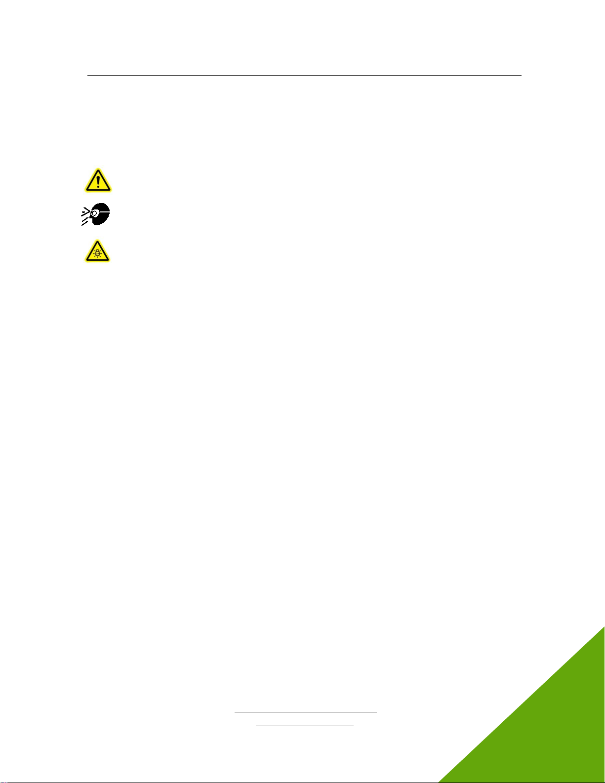
Figure 5 Bottom View
Icon
Description
Always On –The device will continuously emit UV energy
On when Unoccupied –The device will only emit UV energy if no
motion is detected
On when Occupied –The device will only emit UV energy if motion is
detected
Table 1 Emission Selector Switch Descriptions-see section 5.2 for details
Figure 6 Mounting Bracket
Emission Selector
Switch (see
descriptions below)
Mounting height
measurement surface
(bottom of bracket)

Kepri™
UV LED Upper-Air System
http://www.excelitas.com
Excelitas Canada Inc. 2022
All rights reserved
035-xxxxxR, rev.1
7
035-00725R
4 Installation
4.1 Site Inspection
Before you install the device, verify the following:
•The potential installation location has a minimum ceiling height of 2.7m (9ft).
•The potential installation location has a nearby installed AC power receptacle easily reachable
with the Excelitas-supplied detachable AC power cord. If there is no nearby accessible outlet,
you may use your own CSA/UL safety approved AC power extension cord under your own
responsibility.
•The area is free of any elevated flooring which might position a person above the surface used
to determine the minimum ceiling height.
•Do not install the device in the following locations. Examples include:
•Stairways
•Upper floor balconies
•Mezzanines
•Atriums with multiple levels/tiers
•The area in front of the potential location is free of any artifacts that may obscure the emitted
UV energy. Do not install the device if items are within 6ft of the front window; examples include
but are not limited to the following:
•Sound-deadening material
•HVAC ductwork
•Lighting fixtures
•Electrical or mechanical service conduit
•Artwork
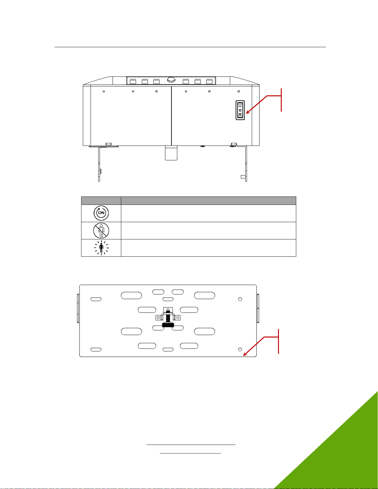
4.2 Wall Bracket Installation
1. Position the bottom of the mounting bracket at least 2.3m (90.5”) from the floor (remember the
minimum ceiling height is 2.7m or 9’). Refer to Figure 7.
2. With 6 screws (M4 or #8) secure the mounting bracket to the wall using the appropriate wall
anchors.
Figure 7 Mounting Bracket with Wall Mounting Holes Highlighted
Surface used for
floor-to-bracket
distance
measurement
M4 or #8 screw hole
locations (x6)
Kepri™
UV LED Upper-Air System
http://www.excelitas.com
Excelitas Canada Inc. 2022
All rights reserved
035-xxxxxR, rev.1
8
035-00725R
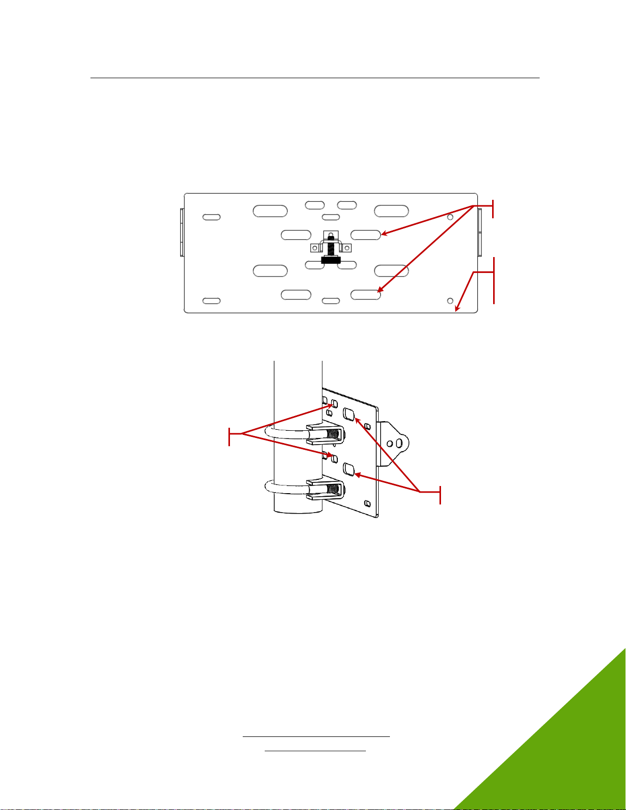
4.3 Pendant Bracket Installation
1. Select two clamping bolts based on the size and shape of the pendant.
2. Position the bottom of the mounting bracket at least 2 3m (90.5”) from the floor. Refer to Figure 8.
3. Secure the clamping bolts to a pair of slots on the mounting bracket. Refer to Figure 9.
Figure 8 Mounting Bracket with Measurement Surface
Figure 9 Mounting Bracket Secured to Pendant
Surface used for
floor-to-bracket
distance
measurement
Slot pair #1
Slot pair #2
Slot pair #3
Kepri™
UV LED Upper-Air System
http://www.excelitas.com
Excelitas Canada Inc. 2022
All rights reserved
035-xxxxxR, rev.1
9
035-00725R
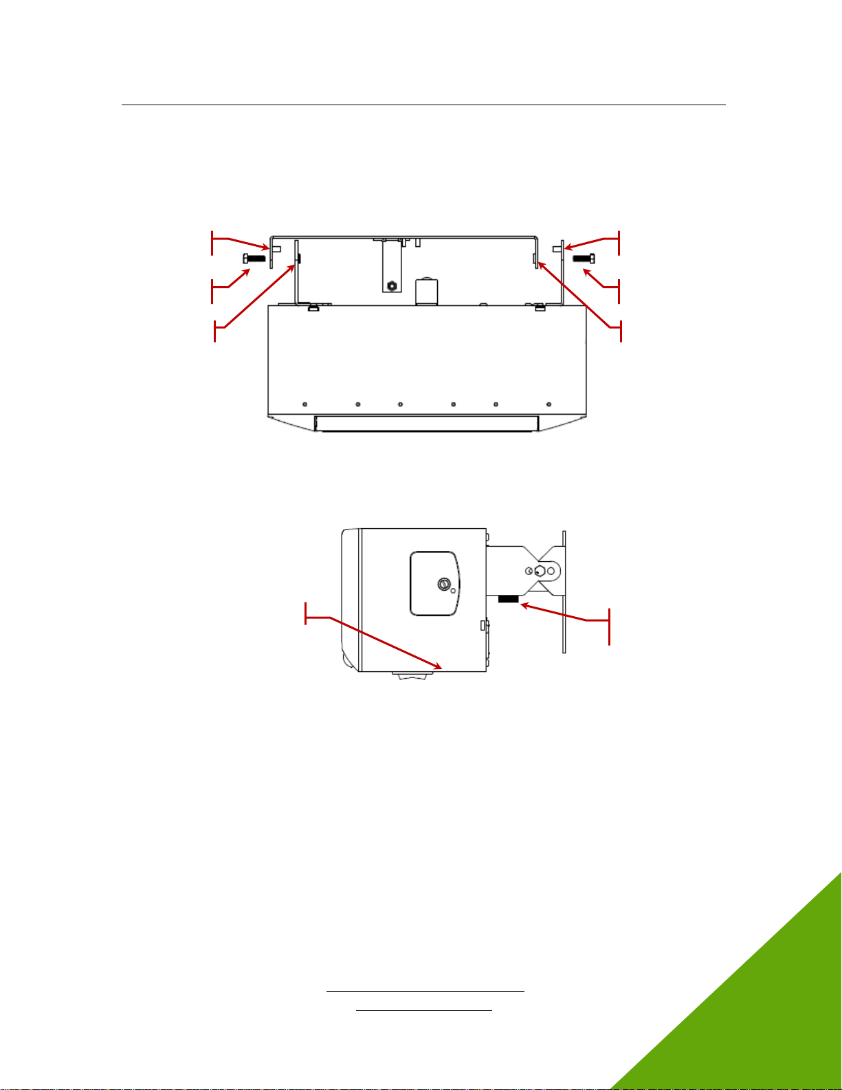
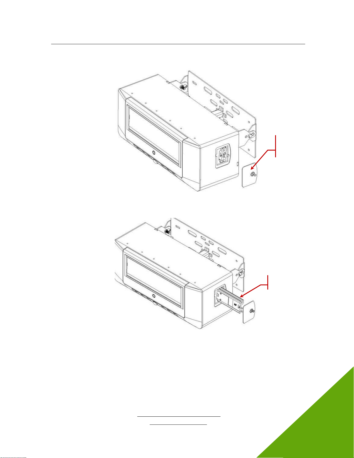
4.4 Securing Kepri to the Mounting Bracket
1. Slide the Kepri module into the wall bracket and use the guide pins to engage the corresponding
holes. Refer to Figure 10.
Figure 10 Kepri Module Engaging the Wall Bracket
2. Adjust the module so the bottom of the device is approximately parallel with the floor. Refer to
Figure 11.
Figure 11 Kepri Side View with Bottom Approximately Parallel to the Floor
3. Secure the Kepri module with the side screws; use an 8mm nut driver to lock firmly. Refer to
Figure 10.
Side Screw
Guide Pin
Hole
Guide Pin
Side Screw
Hole
Bottom surface
Angular fine
adjustment
screw

Kepri™
UV LED Upper-Air System
http://www.excelitas.com
Excelitas Canada Inc. 2022
All rights reserved
035-xxxxxR, rev.1
10
035-00725R
5 Operation
5.1 Powering Up
1. Ensure that the Kepri module is securely mounted as described in Section 4, “Installation”.
2. Verify that the power supply is connected to a properly grounded AC outlet.
3. Insert the supplied detachable AC power cord into power receptacle in the rear. Refer to Figure 3.
4. Turn the power switch ON. The switch is located next to the power receptacle on the back of the
unit. At this time no UV energy is being emitted. The power indicator should be green. Refer to
Figure 2.
5. Adjust the angle of the Kepri module until the Tilt indicator is green. This may require you to
loosen the side screws; but do not remove the screws. The target range is 1° - 5°; use the fine
adjustment screw if necessary. Refer to Figure 11.
6. Secure the side screws firmly once the Tilt indicator is green. The UV Enable indicator will begin
to flash red.
7. Set the Emission Selector Switch to the desired setting. Refer to Table 1.
8. Remove the protective film over the emission window.
9. Ensure the area in front of the device is clear of any obstructions. Refer to section 4.1 for details.
10. To enable UV emission, press the UV Enable button. The UV Enable red indicator will stop
flashing and become unlit.
After 30 seconds, the device will begin to emit UV energy. The UV Enable indicator will become
solid red (not blinking) when UV emissions have started.
Note UV emission will begin depending on the position of the Emission Selector Switch. Refer to
Table 1.
5.2 Understanding How the Emissions Work
Emission Selector Switch and the Motion Indicator
The Emission Selector Switch (refer to Figure 5) controls when the device emits UV energy. The
switch relies on an industry-leading motion detector sensor with a field of view of approximately 110°
(refer to Figure 12). When motion is detected, the Motion indicator turns green.
If the switch is set to Always On, Kepri will continuously emit UV energy regardless of the status of the
motion detector.
Kepri™
UV LED Upper-Air System
http://www.excelitas.com
Excelitas Canada Inc. 2022
All rights reserved
035-xxxxxR, rev.1
11
035-00725R
If the switch is set to one of the other two settings, Kepri relies on the motion sensor to determine
when UV Emissions starts and stops: Expect a 15 second delay when the unit will power on or off
with the motion sensor.
Emission Selector is set
to
UV Emission Starts
UV Emission Stops
Always On
Kepri will continuously emit UV energy regardless of the status
of the motion detector.
On when Occupied
When motion is detected.
UV indicator is solid red.
15 minutes after motion is last
detected.
UV indicator is unlit.
On when Unoccupied
15 minutes after motion is last
detected.
UV indicator is solid red.
When motion is detected.
UV indicator is unlit.
Table 2 Emission Start and Stop
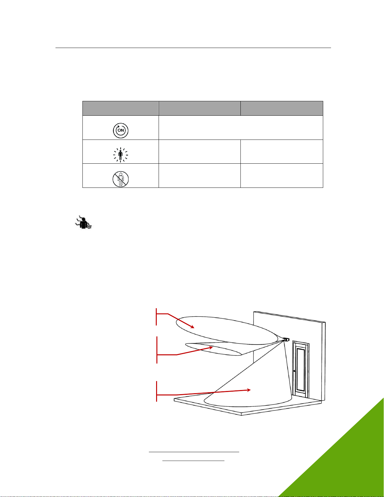
Presence Indicator
The Presence detection sensor increases device safety. This sensor detects IR radiation from a
human body, not movement, to identify when a person enters the UV emission area. The sensor's field
of view or coverage is focused at the most intense portion of the UV beam. The sensor will not cover
every portion of the room. Refer to Figure 12.
When presence is detected, the Presence indicator will turn solid red and emission stops until 30
seconds after presence is no longer detected.
When presence is not detected, the Presence indicator will be unlit and the UV emissions operate
according to the Emission Selector Switch as described above.
Figure 12 Sensor Detection Areas
UV emission area
Presence sensor detection area
–triggered by IR (heat) from
human body, not movement
Motion sensor detection area
–triggered by any movement

Kepri™
UV LED Upper-Air System
http://www.excelitas.com
Excelitas Canada Inc. 2022
All rights reserved
035-xxxxxR, rev.1
13
035-00725R
6 Troubleshooting
If problems persist beyond these troubleshooting points, please contact Excelitas Technologies
Service Department (refer to Section 10, “Contact Information”).
6.1 Failure to Power Up
If the Kepri unit fails to power up or function properly, use the following checklist to eliminate the most
common causes of problems. Check for the following:
•Power Connection Check:
•The power supply cord is securely connected to a grounded (earthed mains socket)
functional outlet.
•The power supply cord is securely connected to the “Power” receptacle on the rear of the
Kepri unit.
•The main power switch on the back of the unit is in the ON position.
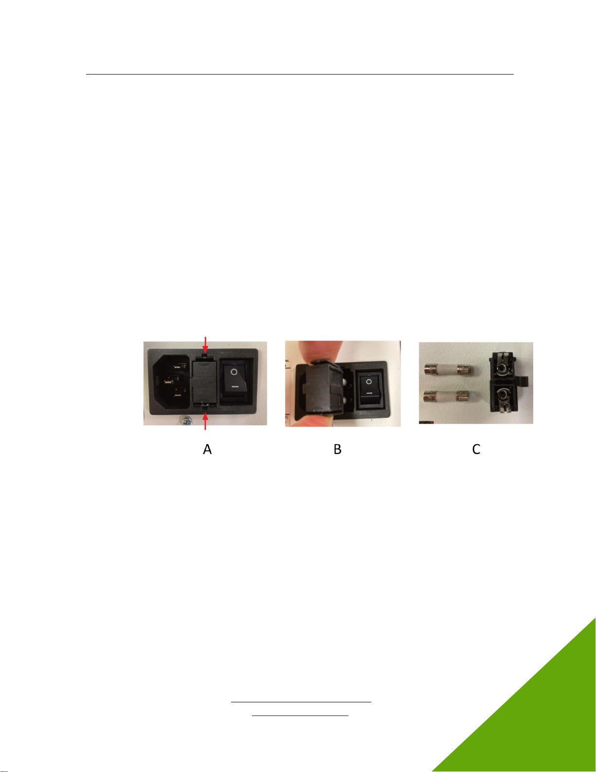
•Fuse Check:
•Check both main power fuses. First disconnect the power cord, then carefully remove the
fuse tray assembly next to the AC receptacle on the rear of the unit.
Note Depending on the orientation of the AC receptacle, the fuse tray may be below or
beside it. The red arrow in Figure 13 (A) shows where a flat screwdriver can be inserted to
gently pull out the fuse tray.
Figure 13 Location and Removal of Fuse Tray in AC Receptacle
•If either or both of the fuses are open, replace with the same type (F6.3A, 250V).
•Note To determine if a fuse is intact (i.e. OK) or open (i.e. blown), remove the fuse from
the tray and check with a multimeter set to resistance (Ω). An intact fuse will read “0Ω” (or
another very low value), an open fuse will have an extremely high Ω reading.
•Note Fuses that chronically need to be replaced are usually a signal that something is
wrong and you should contact Technical Support.
•Unit Door Check:
•Verify the door screws of main unit are tight.
Kepri™
UV LED Upper-Air System
http://www.excelitas.com
Excelitas Canada Inc. 2022
All rights reserved
035-xxxxxR, rev.1
14
035-00725R
7 Care and Maintenance
7.1 General
Kepri is designed to be a very low maintenance system with only one consumable component –the
replaceable LED array. By maintaining the following conditions, performance will be maximized and
risk of future problems will be reduced.
•Always disconnect the device before servicing.
•Never touch the emission window with fingers, tools, or other abrasive/sticky/sharp materials,
fluids, or other materials except as described in section 7.3.
•Never look directly into the emission window while ON.
•If cleaning is required, follow the directions in section 7.3.
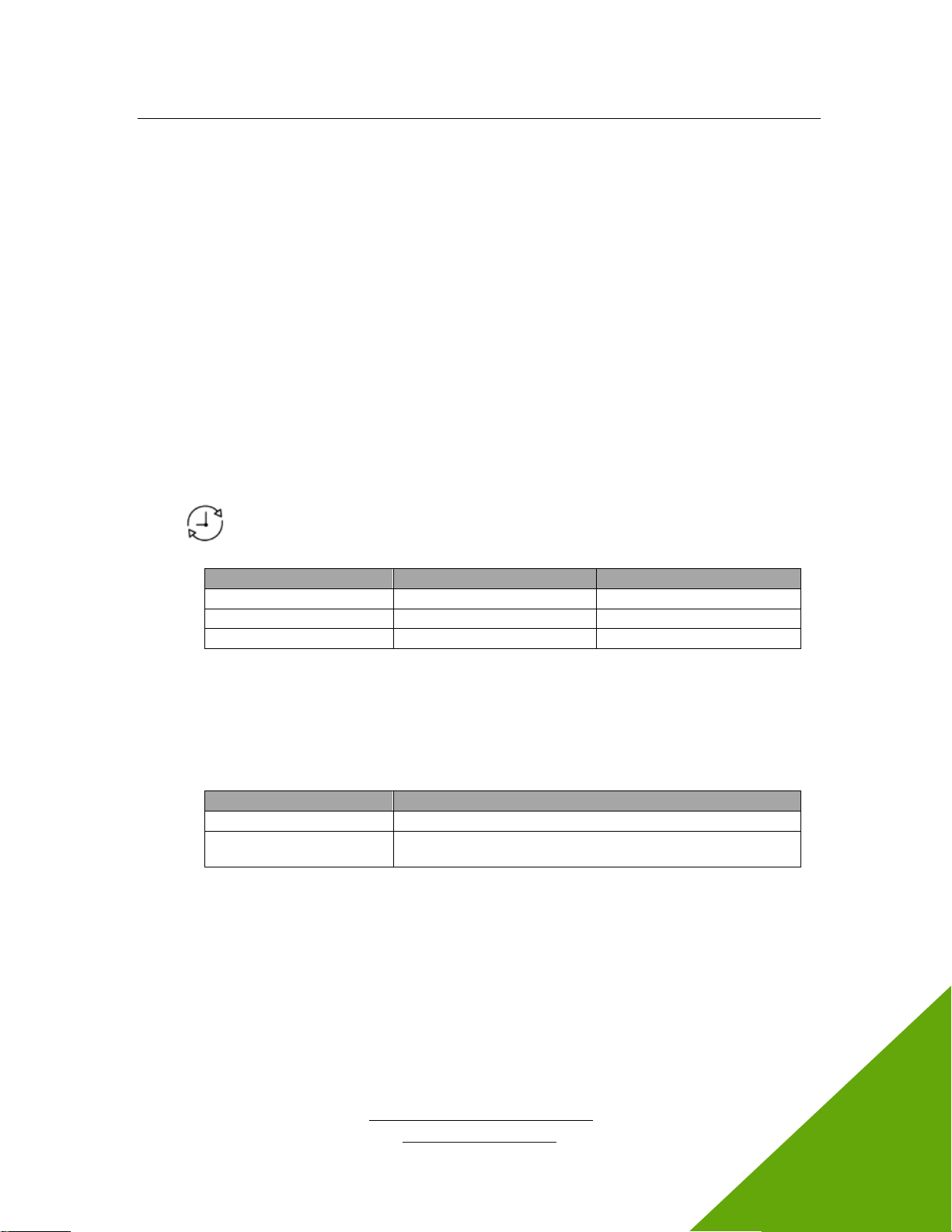
7.2 Monitoring and Replacing the LED Array
Kepri is equipped with a replaceable LED array that allows the module to utilize the latest in UV LED
technology. The device maintains an internal clock and indicates the percentage of remaining life. This
is reflected in the color of the Lifetime indicator:
Lifetime Indicator Color
Percentage of Life Remaining
Suggested Action
Green
10-100%
-
Amber
1-10%
Order replacement array
Red
0
Change LED array
Table 3 Lifetime Indicator Color Descriptions
Note Regardless of the color, the device will continue to emit UV energy.
Replacing the LED Array
When the Lifetime indicator turns amber or red, it is time to replace the LED array.
Replace the LED module with the following Excelitas Technologies part numbers:
Part Number
Description
016-00499R
Printed circuit board assembly (not sold)
012-00129R
Printed circuit board assembly (p/n: 016-00499R) with extrusion
(for purchase)
Table 4 LED Array Replacement Part Numbers
1. Using the ON/OFF switch, turn the Kepri device off.
2. Disconnect the power cord from the receptacle located on the rear of the device.
3. With a small flat head screwdriver, unscrew the bolt on the LED replacement door and remove the
door. Refer to Figure 14.
Kepri™
UV LED Upper-Air System
http://www.excelitas.com
Excelitas Canada Inc. 2022
All rights reserved
035-xxxxxR, rev.1
15
035-00725R
Figure 14 LED Replacement Door Removed
4. With your fingers, remove the LED array. Refer to Figure 15.
Figure 15 LED Array Partially Removed
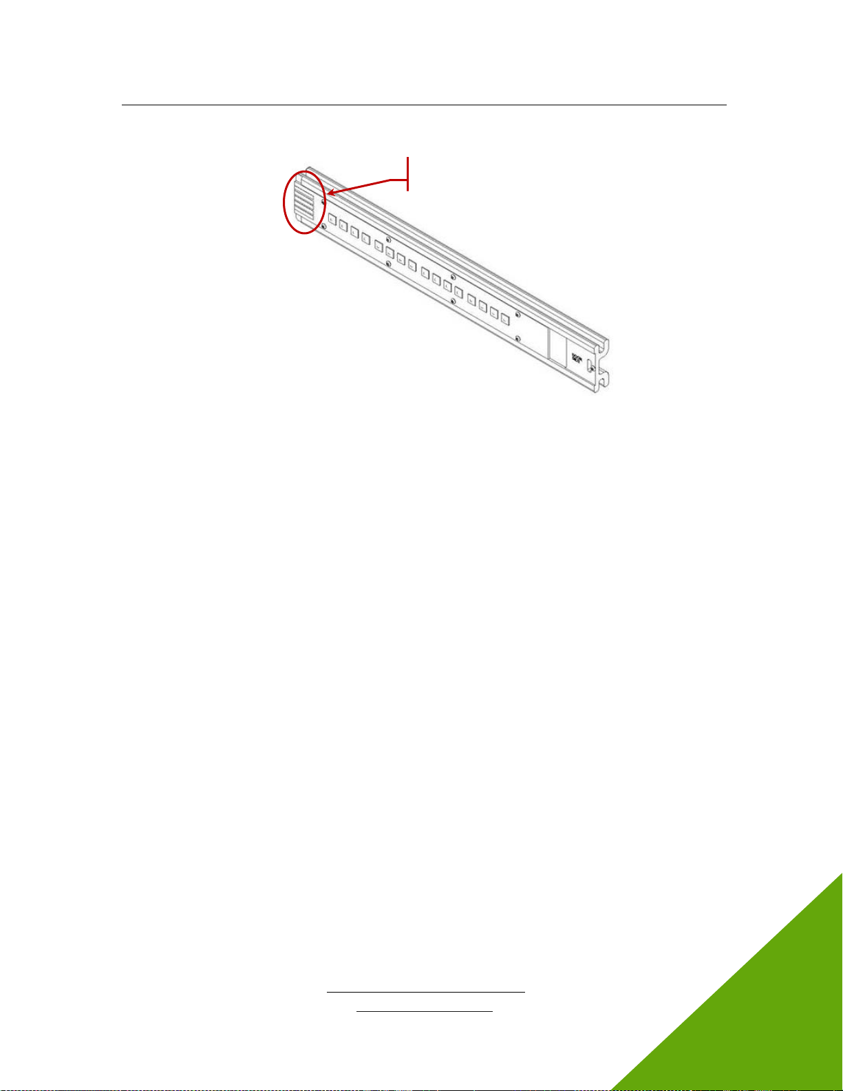
5. Insert the replacement array into the device, so the area with the contact pads enters the device
first. Refer to Figure 16.
LED Array
Replacement
Door
LED Array
Kepri™
UV LED Upper-Air System
http://www.excelitas.com
Excelitas Canada Inc. 2022
All rights reserved
035-xxxxxR, rev.1
16
035-00725R
Figure 16 LED Replacement Array with Contact Pads Highlighted
6. Attach the LED replacement door to the Kepri module.
7. Tighten the screw attached to the door.
8. Plug the power cord into the receptacle.
9. Turn the device ON. See sections 4.4 and 5.1 for further details.
7.3 Cleaning
Exterior Surfaces
If necessary, exterior surfaces can be cleaned with a mild soap and water solution and lint-free cloth.
•Turn the unit off and disconnect AC power prior to cleaning.
•Use a damp cloth only - do not allow cleaning solution to get into any ports, air vents or seams.
•Avoid the emission window.
•Allow the unit to dry before turning it back on.
Front Window
Cleaning of optical surfaces is not generally required. However, if any visible contamination or
fingerprints appear on the lens surface, cleaning may be necessary.
Recommended cleaning materials:
•Compressed air can duster
•Lint-free lens tissue, lint-free cotton swabs
•Powder-free gloves or finger cots
•Lens cleaning solution, reagent-grade isopropyl alcohol, or another appropriate solvent
Cleaning procedure:
1. Use a compressed air can duster to blow off any loose lint, dust or other contaminants.
2. If the contaminant is a fluid (e.g., water, immersion oil), first use a dry lens tissue to wick away as
much as possible –do not wipe.
3. Saturate a corner of the lens tissue (or cotton swab) with cleaning solvent, and gently wipe the
optical surface in one pass. Take care not to “flood” the area with solvent.
4. Repeat the previous step with a fresh portion of lens tissue–this will help avoid recontamination of
the optical surface and minimize the amount of cleaning required.
Contact
Pads
Table of contents


