Excell ES1-1 User manual
Multi-Purpose Spray Gun
Instruction manual
for model ES1-1
IMPORTANT
Please make certain that the person who is to use this equipment
carefully reads and understands these instructions before starting
operations.
Part No. D28262 Rev. 0 12/30/02
2- ENG
D28262
• SAVE THESE INSTRUCTIONS •
IMPROPER OPERATION OR MAINTENANCE OF THIS
PRODUCT COULD RESULT IN SERIOUS INJURY AND
PROPERTY DAMAGE. READ AND UNDERSTAND ALL
WARNINGS AND OPERATING INSTRUCTIONS BEFORE
USING THIS EQUIPMENT.
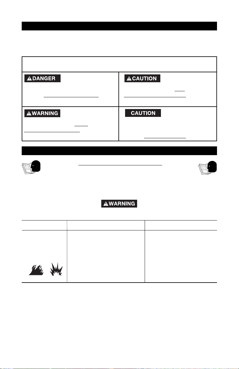
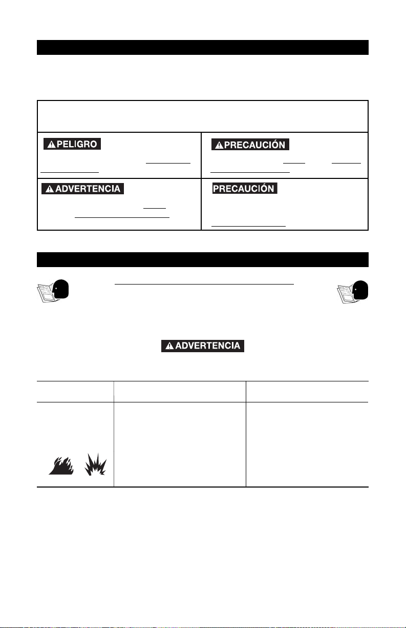
The Following Hazards Can Occur During The Normal Use Of This Product:
HAZARD WHAT CAN HAPPEN HOW TO PREVENT IT
When paints or materials are
sprayed, they are broken into
very small particles and mixed
with air. This will cause certain
paints and materials to become
extremely flammable and could
result in serious injury or death.
Never spray near open flames
or pilot lights in stoves or
heaters.
Never smoke while spraying.
Provide ample ventilation when
spraying indoors.
RISK OF
EXPLOSION OR
FIRE -
FLAMMABLE
MATERIALS
SAFETY GUIDELINES - DEFINITIONS
Indicates an
imminently hazardous
situation which, if not avoided, will
result in death or serious injury.
Indicates a potentially
hazardous situation
which, if not avoided, could result in
death or serious injury.
Indicates a potentially
hazardous situation
which, if not avoided, may result in
minor or moderate injury.
Used without the
safety alert symbol
indicates a potentially hazardous
situation which, if not avoided, may
result in property damage.
SAFETY and PREVENTING EQUIPMENT PROBLEMS. To help you recognize this information, we
use the symbols below. Please read the manual and pay attention to these sections.
This manual contains information that is important for you to know and understand. This information
relates to protecting YOUR SAFETY and PREVENTING EQUIPMENT PROBLEMS. To help you
recognize this information, we use the symbols below. Please read the manual and pay attention to
these sections.
IMPORTANT SAFETY INSTRUCTIONS

3- ENG D28262
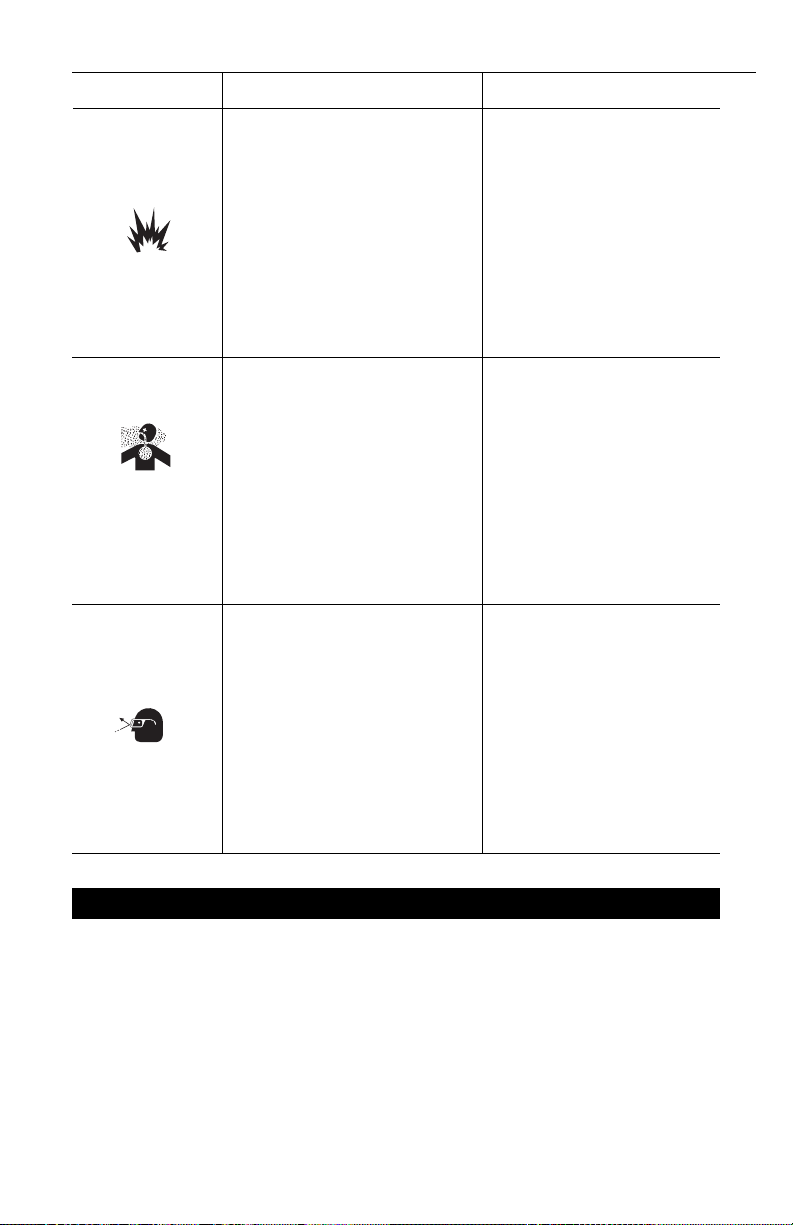
RISK OF
EXPLOSION -
INCOMPATIBLE
MATERIALS
HAZARD WHAT CAN HAPPEN HOW TO PREVENT IT
SPECIFICATIONS
Air Inlet 1/4 NPT
Maximum Air Pressure 60 psi.
Recommended Operating Air Pressure 50 psi.
Air Consumption @ 50 psi. 9.8 scfm (100% usage)
Cup Capacity 32 oz. (946 cc)
Nozzle Size 1.6 mm
The solvents 1,1,1-Trichloroethane
and Methylene Chloride can
chemically react with the alumi-
num used in most spray equip-
ment, and this gun and cup, to
produce an explosion hazard and
could result in serious injury or
death.
Read the label or data sheet for
the material you intend to spray.
1. Never use any type of
spray coating material
containing these solvents.
2. Never use these solvents
for equipment cleaning or
flushing.
3. If in doubt as to whether a
material is compatible,
contact your material
supplier.
Some paints, coatings and
solvents may cause lung damage,
and burns if inhaled or allowed to
come into contact with skin or
eyes.
Use a NIOSH approved mask
or respirator and protective
clothing designed for use with
your specific application and
spray materials. Some masks
provide only limited protection
against toxic materials and
harmful paint solvent. Consult
with a Safety Expert or Industri-
al Hygienist if uncertain about
your equipment or materials.
RISK TO
BREATHING
RISK FROM
FLYING OBJECTS Certain parts are under pressure
whenever the gun is connected to
a pressurized air line. These parts
may be propelled if the gun is dis-
assembled.
Compressed air may propel dirt,
metal shavings, etc. and possibly
cause an injury.
Prolonged exposure to air spray
can result in permanent damage
to hearing.
Disconnect the gun from the air
line, or completely depressurize
the air line whenever the gun is
to be disassembled.
Never point any nozzle or
sprayer toward a person or part
of the body.
Always wear ANSI 278.1 safety
approved goggles or glasses
when spraying.
Always wear hearing protection
when operating spray equip-
ment.
This spray gun has a siphon and pressure feed setting. It is set at the factory for
siphon feed application, which makes it ideal for applying light and medium
bodied paints (stain, lacquer) to large size jobs such as complete auto
refinishing. The pressure feed application is used when material being sprayed is
too heavy for siphon feed or fast application is desired. The pressure feed
setting allows the gun to be used with remote paint tank for spraying on larger
painting applications.
Before use
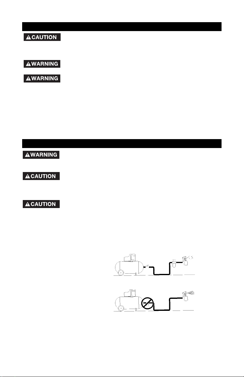
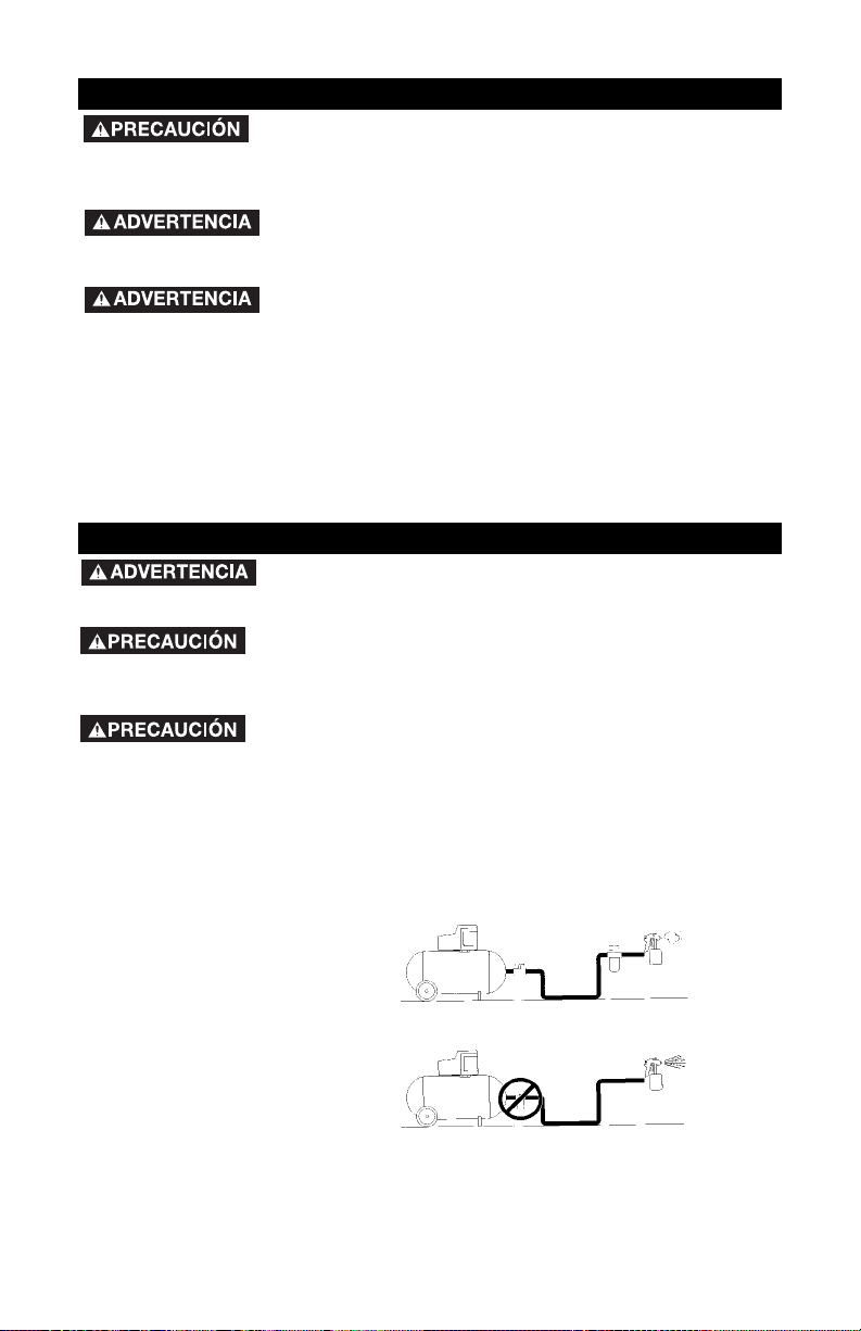
●Install a moisture
separator/regulator when there
is a possibility moisture will
damage the surface to be
painted. Install the moisture
separator/regulator as close to
the tool as possible.
NOTE: Liquid water occurs
naturally in air lines as a result
of compression. The moisture
exiting near the compressor is
warm and still in a vapor state which allows it to pass through the moisture
separator. The vapor must travel a minimum of 5 to 10 feet to cool down to
a liquid to be removed by the moisture separator. See Illustration.
●Prior to shipment, this gun was treated with an anticorrosive agent. Before
using this gun make sure that it is carefully flushed with thinner.
4- ENG
D28262
Before disassembly or removal of any part of gun or
attached components, shut off compressor, release
pressure by depressing trigger, and disconnect power source. NEVER as-
sume system pressure is zero!
TO AVOID CREATING AN EXPLOSIVE ATMOSPHERE,
WORK ONLY IN WELL-VENTILATED AREAS.
USE OF A NIOSH APPROVED FACE MASK IS
RECOMMENDED TO PREVENT INHALATION OF TOXIC
MATERIAL.
DO NOT ATTEMPT TO UNCLOG (BACK FLUSH) SPRAY GUN
BY SQUEEZING TRIGGER WHILE HOLDING FINGER IN
FRONT OF FLUID NOZZLE.
Pressure may vary according to viscosity of material used.
Maximum working pressure of gun is 60 psi. DO NOT
EXCEED PRESSURE LIMIT OF GUN OR ANY OTHER COMPONENT IN
SYSTEM!
Prior to daily operation, make certain that all connections
and fittings are secure. Check hose and all connections for
a weak or worn condition that could render system unsafe. All replacement
components such as hose or fittings must have a working pressure equal
to or greater than system pressure.
GENERAL INFORMATION
OPERATION
Siphon Feed
TO USE
1. Mix material according the
manufacturer’s instructions. Mixture
should be smooth and easily pourable.
Lumps or foreign particles should be
removed by straining through a
suitable paint filter.
NOTE: When applying heavy bodied paints,
the Air Cap (included, part number
D26452) is recommended.
NOTE: If not using the siphon feed setting,
see “Internal Pressure Feed” or “Remote
Pressure Feed” paragraphs.
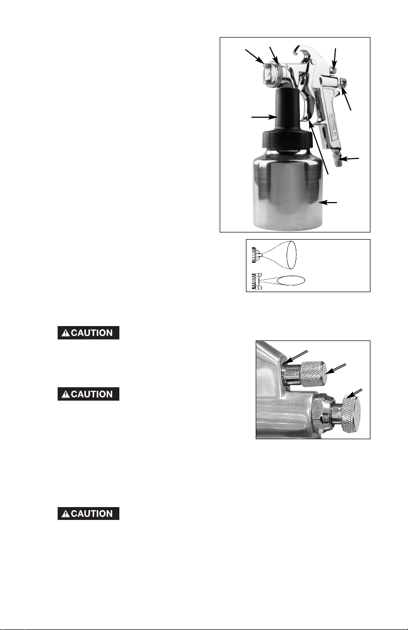
2. Fill the material cup (e) 3/4 full.
3. Attach material cup (e) to the gun
securely.
4. Attach air supply line to 1/4 NPT air
inlet (c).
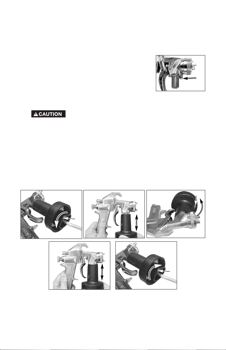
5. Adjust spray pattern.
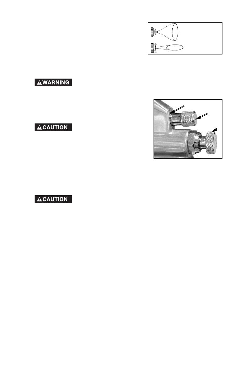
a. The position of the air cap horns (g) will
determine the spray pattern. Loosen air
cap (h) and rotate horns to achieve
desired pattern. Tighten air cap.
6. Turn fluid control knob (b) clockwise until it
stops, do not force. This will shut off the fluid flow. NOTE: The fluid or
density of “fan spray” is controlled by fluid control knob (b).
7. Adjust air pressure to 50 psi at air compressor.
DO NOT exceed 60 psi.
8. Turn air valve control knob (a)
counterclockwise until first thread is flush with
gun body. NOTE: Air flow is controlled by air
valve control knob (a).
DO NOT turn air valve
control knob or fluid control
knob out until the first thread is past the gun
body. They are under pressure when the gun
is triggered and could leave the gun with
force.
NOTE: Care should be exercised when handling spray gun to avoid damage to
the orifice of the air cap and tip of fluid nozzle. Damage to these parts results in
irregular spray patterns.
9. Depress spray gun trigger (d) and gradually turn the fluid control knob (b)
counterclockwise until desired fluid flow is reached. Trigger gun quickly, one
second on-off to test pattern.
NEVER point spray gun at self or any other person. Ac-
cidental discharge of material may result in serious
injury.
NOTE: If gun sprays too fast, decrease the air and fluid pressure. If too slow,
increase the pressure. Turn fluid control knob (b) counterclockwise to increase,
or clockwise to decrease, the fluid flow. Turn air valve control knob (a) counter-
clockwise to increase, or clockwise to decrease, the air flow.
NOTE: When using the internal mix air cap, begin with the same air and fluid
pressure.
5- ENG D28262
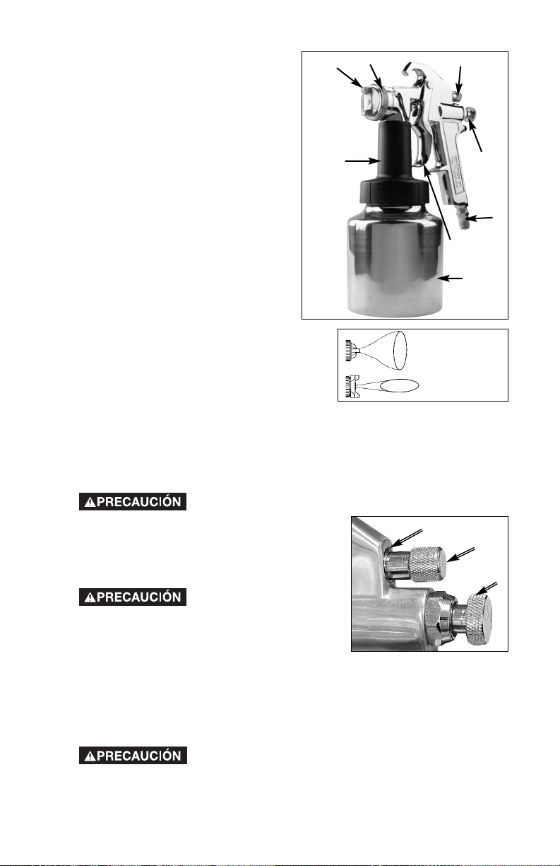
e
f
a
b
g
c
d
h
Horizontal position
Vertical position
a
b
first thread flush
Convert to and Use Internal Pressure Feed:
If the material to be sprayed is too heavy for siphon feed or fast application is
desired, convert to the pressure feed setting.
1. Remove the material cup (e) from gun.
2. Turn shroud retaining sleeve (k) counterclockwise until the shroud can be
pulled down and is free to rotate (approximately 1/4”)
3. Rotate the shroud until the pressure arrow (l) is facing forward away from
the handle, push shroud up into place and hand tighten the shroud retaining
sleeve.
4. Fill the material cup (e) 3/4 full.
5. Attach material cup (e) to the gun securely.
6. Attach air supply line to 1/4 NPT air inlet (c).
Convert to Remote Pressure Feed:
1. Remove the material cup (e) from gun.
2. Unscrew the shroud retaining sleeve (k) and remove the shroud, shroud
retaining sleeve, fluid tube, and gaskets from the gun. NOTE: To avoid loss
and damage to small parts store them in the material cup and assemble the
shroud to the material cup.
3. Install thread forming screw (m) (included with spray
gun, part number D26452) into the small pressure port
located on the surface where the shroud gasket seats.
The screw should be tightened until the shoulder
contacts the spray gun body.
4. The spray gun is now ready to be connected to any
pressure feed tank with a standard 3/8" straight pipe
female connection. See manufacturer’s manual for correct procedure.
5. To operate see steps 2-9 in the “To Use” section to continue.
NEVER point spray gun at self or any other person.
Accidental discharge of material may result in serious
injury.
6- ENG
D28262
m
k
l
k
7- ENG D28262
Spraying Tips
1. The stroke is made with a free arm motion, keeping the gun at a right angle
to the surface at all points of the stroke. Arching the stroke will result in
uneven application and excessive over spray at each end of the stroke.
2. Depress trigger just before reaching the edge of the surface to be sprayed.
Hold the trigger fully depressed and move the gun in one continuous
motion. Release the trigger when the other edge of the surface is reached,
shutting off the fluid flow, but continue motion a few inches until it is
reversed for the return stroke. When the edge of the surface is reached on
the return stroke, depress the trigger fully again and continue across the
surface.
3. Lap each stroke 50% over the preceding one. Less than 50% will cause
streaks on the finish surface.
7. Adjust spray pattern.
a. The position of the air cap horns (g) will
determine the spray pattern. Loosen air
cap (h) and rotate horns to achieve
desired pattern. Tighten air cap.
8. Turn fluid control knob (b) clockwise until it
stops, do not force. This will shut off the fluid flow. NOTE: The fluid or den-
sity of “fan spray” is controlled by fluid control knob (b).
9. Adjust air pressure to 40 psi at air compressor.
Risk of bursting or equipment damage. When the gun is
operated at pressure feed with the cup attached, air
pressure must not exceed 50 psig.
10. Turn air valve control knob (a)
counterclockwise until first thread is flush with
gun body. NOTE: Air flow is controlled by air
valve control knob (a).
DO NOT turn air valve
control knob or fluid control
knob out until the first thread is past the gun
body. They are under pressure when the gun
is triggered and could leave the gun with
force.
NOTE: Care should be exercised when handling
spray gun to avoid damage to the orifice of the air cap and tip of fluid nozzle.
Damage to these parts results in irregular spray patterns.
11. Depress spray gun trigger (d) and gradually turn the fluid control knob (b)
counterclockwise until desired fluid flow is reached. Trigger gun quickly, on
second on-off to test pattern.
NEVER point spray gun at self or any other person.
Accidental discharge of material may result in serious
injury.
NOTE: If gun sprays too fast, decrease the air and fluid pressure. If too slow,
increase the pressure. Turn fluid control knob (b) counterclockwise to in-
crease, or clockwise to decrease, the fluid flow. Turn air valve control knob (a)
counterclockwise to increase, or clockwise to decrease, the air flow.
NOTE: When using the internal mix air cap, begin with the same air and fluid
pressure.
Horizontal position
Vertical position
a
b
first thread flush

8- ENG
D28262
Always exercise extreme care when using any solvent or
thinner. Never clean gun near fire, flame, or any source of
heat or sparks. Properly dispose of used cleaning materials.
DO NOT soak entire spray gun in solvent or thinner for a
long period of time as this will destroy lubricants and
possibly make motion uneven. NEVER use lye or caustic alkaline solution
for cleaning. Such solutions will attack aluminum alloy parts of gun.
It is important that spray gun be cleaned after daily use. Cleaning is accom-
plished by spraying appropriate solvent or thinner through system. Cleaning
NOTE: Clean gun immediately after use. Paint and other materials dry
quickly in the small passages.
1. Turn off air supply to gun.
2. Loosen the material cup and remove the fluid tube from the material. Hold
the tube over the cup and pull the trigger to allow the paint to drain back
into the cup.
When using the remote pressure feed method: See manufacturer’s
manual for suggested cleaning of remote cup or tank.
3. Empty material from material cup and replace with a suitable solvent. If
using water based material use mineral spirits to prevent corrosion.
4. Turn air supply on and operate trigger until all material traces have disap-
peared and gun is thoroughly clean.
IMPORTANT: Do not immerse the gun in solvent, this will cause damage to
the packings.
NOTE: Always comply with local codes when disposing of solvents.
5. Remove air cap and immerse in a suitable solvent.Use a bristle brush to
clean dried paint and blow it dry with compressed air.
6. Use cleaning tool (supplied) to clean small clogged holes.
7. Wipe gun with a solvent soaked cloth.
IMPORTANT: Make certain air cap and fluid nozzle are kept clean at all
times. DO NOT use hard objects to clean clogged holes. The smallest
amount of damage may cause irregular spray pattern.
Lubrication
Lubrication procedures must be observed after thoroughly cleaning the gun to
ensure effective, high quality performance of spray gun.
1. Lubricate working points with straight mineral oil, or castor oil.
2. Periodically, place a few drops of oil on tapered sections of fluid nozzle to
ensure easy operation of air cap. When spraying water base materials, coat
fluid nozzle inside and outside with straight mineral oil after each use.
MAINTENANCE
9- ENG D28262
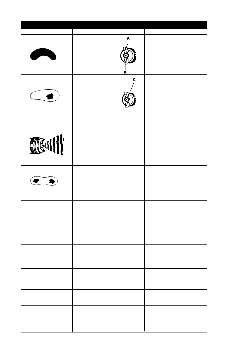
Dried material
is clogging
side-port “A”
and causing
side-port “B” to
blow spray
towards the
clogged side
A. Soak side-ports in
thinner to clean clog.
DO NOT poke any
opening with hard
objects.
B. Dried material at
fluid nozzle “C”
restricts air flow
Loose air nozzle
Air pressure set
too high
Remove air nozzle.
Wipe off fluid tip using a
cloth soaked in thinner
or by soft brush
Fasten nozzle securely
Reduce air pressure
C. Spitting, irregular
or fluttering spray
Fluid nozzle cracked or worn
Leak at thread of fluid nozzle
Leak at fluid needle
Needle packing worn out
Insufficient fluid in cup
Vent hole in container cover
clogged
Tighten or replace
Tighten fluid nozzle
Tighten compression nut
assembly or replace
needle packing
Replace packing
Fill cup with fluid
Clean Out
D. Split spray pattern Air pressure too high Turn pattern control
knob clockwise to
decrease fan width.
Turn fluid needle
adjusting nut counter-
clockwise to increase
fluid flow
Material too heavy
Insufficient air pressure
Fluid pressure too high
Dried material on tip of fluid
nozzle or air jets of air cap
Thin material or use
larger orifice fluid nozzle
set
Increase pressure to
within limit
Reduce pressure
Clean
Air needle partially closed
Dried material in air jets or air
cap
Obstruction in air line
Remove obstruction
Reduce air pressure
and/or open fluid control
knob
Air pressure to high for
viscosity of fluid
Loose cup or foreign sub-
stances on/between cup
thread and fluid inlet
Tighten and clean or
replace it
F. Inadequate air de-
livery
E. Unatomized or
spattered spray
G. Excessive fog
I. Material leaking
from nozzle when
trigger is released
H. Material leaking
from fluid inlet of
cup.
Worn fluid needle
Dried material in tip of nozzle
Loose packing nut
Replace
Clean
Tighten needle packing
nut by turning
counterclockwise
Defective Pattern Likely Cause Suggested Remedy
TROUBLESHOOTING
Open control knob
Clean
10- ENG
D28262
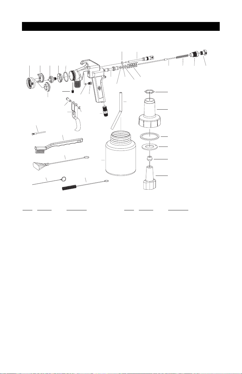
PARTS LIST
12456
19
12
11
33
34
35
30
29
32
24
28
27
26
25
2120
8
7
22 23
31
18
15
17
16 14
36 37
13
3910
Key # Part No. Description
1 D26451 Retaining Ring
2 D26452 Air Cap
3 D26453 Air Cap
4 D26454 Fluid Tip
5 * Baffle
6 * O-ring
7 * O-ring
8 D26458 Air Valve Assembly
9 * Packing Retainer
10 * Fluid Needle Assembly
11 D26461 Trigger
12 D26462 Screw
13 D25172 E-Ring
14 D26463 Air Valve Spring
15 * O-Ring
16 * Gasket
17 * O-Ring
18 D26464 Valve Stem Assembly
19 D26465 Screw
Key # Part No. Description
20 D26466 Fluid Needle Assembly
21 D26467 Spring
22 D26468 Retaining Nut
23 D26469 Fluid Needle Adjusting Screw
24 D26470 Adapter ¼ NPT x ¼ NPS
25 * Gasket
26 D26472 Shroud
27 * Cup Gasket
28 * Washer
29 * Compression Ring
30 D26476 Retaining Sleeve
31 D26477 Fluid Tube
32 D26478 Cup
33 D26479 Copper Grip Brush
34 D26480 Plastic Grip Brush
35 D26481 Witch Brush
36 D26482 Needle
37 D26483 Brush
* Only available in Seal Kit part number D23931

11- ENG D28262
NOTES

12- ENG
D28262
LIMITED WARRANTY
All merchandise manufactured by DAPC is warranted to be free of defects in workmanship and
material which occur during the first year from the date of purchase by the original purchaser (initial
user). Products covered under this warranty include: air compressors, *air tools, accessories, service
parts, pressure washers, and generators used in consumer applications (i.e., personal residential
household usage only).
Air compressors, *air tools, accessories, service parts, pressure washers, and generators used in
commercial applications (income producing) are covered by a 90 day warranty.
DAPC will repair or replace, at DAPC’s option, products or components which have failed within the
warranty period. Repair or replacement, and service calls on 60 and 80 gallon air compressors, will be
handled by Authorized Warranty Service Centers and will be scheduled and serviced according to the
normal work flow and business hours at the service center location, and depending on the availability
of replacement parts.
All decisions of DAPC with regard to this policy shall be final.
This warranty gives you specific legal rights, and you may also have other rights which vary from state
to state.
RESPONSIBILITY OF ORIGINAL PURCHASER (Initial User):
To process a warranty claim on this product, DO NOT return it to the retailer. The product must be
evaluated by an Authorized Warranty Service Center. For the location of the nearest Authorized
Warranty Service Center call 1-800-888-2468, 24 hours a day, 7 days a week or visit our web site
at www.devap.com.
Retain original cash register sales receipt as proof of purchase for warranty work.
Use reasonable care in the operation and maintenance of the product as described in the Owners
Manual(s).
Deliver or ship the product to the nearest DAPC Authorized Warranty Service Center. Freight
costs, if any, must be paid by the purchaser.
Air compressors with 60 and 80 gallon tanks only will be inspected at the site of installation.
Contact the nearest Authorized Warranty Service Center, that provides on-site service calls, for
service call arrangement.
If the purchaser does not receive satisfactory results from the Authorized Warranty Service
Center, the purchaser should contact DAPC.
THIS WARRANTY DOES NOT COVER:
Merchandise sold as reconditioned, floor models and/or display models. Any damaged or
incomplete equipment sold "as is".
Merchandise used as "rental" equipment.
Merchandise that has become inoperative because of ordinary wear, misuse, freeze damage, use
of improper chemicals, negligence, accident, improper and/or unauthorized repair or alterations
including failure to operate the product in accordance with the instructions provided in the
Owners Manual (s) supplied with the product.
*Air Tools: O-Rings and driver blades are considered ordinary wear parts, therefore, they are
warranted for a period of 45 days from the date of purchase.
An air compressor that pumps air more than 50% during a one hour period is considered misuse
because the air compressor is undersized for the required air demand. Maximum compressor
pumping time per hour is 30 minutes.
Merchandise sold by DAPC which has been manufactured by and identified as the product of
another company. The product manufacturer's warranty will apply.
Repair and transportation costs of merchandise determined not to be defective.
Cost associated with assembly, required oil, adjustments or other installation and start-up cost.
Any incidental, indirect or consequential loss, damage, or expense that may result from ANY
defect, failure or malfunction of the product. Some states do not allow the exclusion or limitation
of incidental or consequential damages, so the above limitation or exclusion may not apply to
you.
Implied warranties, including those of merchantability and fitness for a particular PURPOSE, are
limited to one year from the date of original purchase. Some states do not allow limitations on
how long an implied warranty lasts, so the above limitations may not apply to you.
DAPC
213 Industrial Drive • Jackson, TN 38301-9615
Telephone: 1-800-888-2468
FAX: 1-800-888-9036
Pistola rociadora multipropósito
Manual de instrucciones
Para el modelo ES1-1
IMPORTANTE
Sírvase asegurarse que la persona que utilizará este equipo lea
cuidadosamente y comprenda estas instrucciones, antes de
comenzar a operarlo.
Pieza N° D28262 Rev. 0 12/30/02
• CONSERVE ESTAS INSTRUCCIONES •
LA OPERACIÓN O EL MANTENIMIENTO INADECUADOS DE
ESTE PRODUCTO PODRÍAN DETERMINAR SERIAS LESIONES
Y DAÑOS A LA PROPIEDAD. LEA Y COMPRENDA TODAS LAS
ADVERTENCIAS E INSTRUCCIONES OPERATIVAS ANTES DE
UTILIZAR ESTE EQUIPO.
Pueden ocurrir las siguientes situaciones de peligro durante el uso normal
de este producto:
PELIGRO QUÉ PUEDE OCURRIR CÓMO PREVENIRLO
Cuando se rocía con pinturas o
materiales, ellas se fraccionan
en pequeñas partículas que se
mezclan con el aire. Ello origina
que ciertas pinturas y materiales
se tornen extremadamente
inflamables y puedan causar
serias lesiones o la muerte.
Jamá rocíe en las cercanías de
llama abierta o llamas piloto en
cocinas o calefactores.
Jamás fume mientras esté
rociando.
Al rociar en interiores,
suministre amplia ventilación.
RIESGO DE
EXPLOSIÓN O
INCENDIO -
MATERIALES
INFLAMABLES
NORMAS DE SEGURIDAD - DEFINICIONES
Indica una situación de
peligro inminente que, si
no es evitada, podrá causar la muerte o
serias lesiones.
Indica una situación
potencialmente
riesgosa que, si no es evitada, podría
ocasionar la muerte o lesiones serias.
Indica una situación
potencial de riesgo,
que, si no es evitada, puede causar lesiones
menores o moderadas.
Utilizada sin el símbolo
de alerta de seguridad,
indica una situación potencialmente riesgosa
que, si no es evitada, puede ocasionar
daños a la propiedad.
SEGURIDAD y PREVENCIÓN DE PROBLEMAS AL EQUIPO. Para ayudarlo a identificar esta información
hemos utilizado los símbolos que se indican más abajo. Sírvase leer el manual y prestar atención a dichas
secciones.
Este manual contiene información que resulta importante para que usted conozca y comprenda. Esta
información se relaciona con la protección de SU SEGURIDAD y LA PREVENCIÓN DE
PROBLEMAS A SU EQUIPO. Para ayudarlo a identificar esta información hemos utilizado los
símbolos que se indican más abajo. Sírvase leer el manual y prestar atención a dichas secciones.
IMPORTANTES INSTRUCCIONES DE SEGURIDAD
14-SP
D28262
15-SP D28262
Entrada de aire 1/4 NPT
Máxima presión de aire 60 psi.
Recomendado para operar el aire a presión 50 psi.
Consumo de aire a 50 psi.
9.8 scfm (100% de uso)
Capacidad de la copa 946 cm³ (32 onzas)
Diámetro de la boquilla 1.6 mm
ESPECIFICACIONES
RIESGO DE
EXPLOSIÓN -
MATERIALES
INCOMPATIBLES
PELIGRO QUÉ PUEDE OCURRIR CÓMO PREVENIRLO
Solventes del tipo 1, 1, 1 -
Tricloroetano y Cloruro de
metileno, pueden reaccionar
químicamente con el aluminio
utilizado en la mayoría de los
equipos de rociado, esta pistola y
su copa, produciendo una
explosión que podría determinar
serias lesiones o la muerte.
Lea la etiqueta o la hoja de
especificaciones del material
que usted intenta rociar.
1. Jamás use tipo alguno de
material que contenga esos
solventes.
2. Jamás use esos solventes
para la limpieza del equipo o
su enjuagado.
3. En caso de dudas respecto
a la compatibilidad del
material, contacte a su
proveedor de materiales.
Algunas pinturas, recubrimientos
y solventes pueden causar daños
pulmonares y quemaduras, si son
inhalados o permitidos que tomen
contacto con la piel o los ojos.
Utilice una máscara aprobada
NIOSH o un respirador y ropa
protectora diseñada para ser
usada con su aplicación específica
y materiales de rociado. Algunas
máscaras solo proveen una
protección limitada contra
materiales tóxicos y solventes
dañinos de pinturas. En caso de
incertidumbre acerca de su equipo
o materiales, consulte con un
experto en seguridad o un
higienista industrial.
RIESGO DE
INHALACIÓN
RIESGO DE
OBJETOS
ARROJADOS
Ciertas partes se encuentran
sometidas a presión, cuando la
pistola está conectada a una
tubería de aire comprimido. Esas
partes podrían ser expulsadas si
la pistola fuese desarmada.
El aire comprimido puede arrojar
suciedad, partículas de metal, etc
y posiblemente ocasionar
lesiones.
La exposición prolongada al
rociado de aire puede ocasionar
daños permanentes de audición.
Desconecte la pistola de la
cañería de aire, o despresurice
completamente la misma, cada
vez que la pistola deba ser
desarmada.
Jamás apunte ninguna boquilla
o rociador hacia persona
alguna o parte del cuerpo.
Al rociar, use siempre
antiparras de seguridad ANSI
278.1 aprobadas.
Al operar equipo de rociado,
use siempre protección
auditiva.
Esta pistola rociadora tiene un sifón y elementos de control de la presión. Ellos vienen regulados de
fábrica para el uso del sifón, lo cual los hace ideal para la aplicación de pinturas ligeras y medianas
de carrocería (tinturas y lacas) a trabajos grandes tales como la terminación de un auto. La presión
de alimentación aplicada se utiliza cuando el material que será atomizado resulta demasiado
pesado para una alimentación por sifonado o cuando se desea hacer una aplicación rápida. La
calibración de la presión de alimentación permite que la pistola sea utilizada con un tanque remoto
de pintura, para el rociado sobre aplicaciones de gran tamaño.
Antes de usar:
●Instale un separador / regulador de humedad donde exista la posibilidad de humedad que
pudiese dañar la superficie que debe ser pintada. Instale el separador / regulador de humedad
lo más cercano posible a la
herramienta.
NOTA: El agua en estado liquido ocurre
naturalmente en cañerías de aire como
resultado de la compresión. La
humedad que sale cercana al
compresor es cálida y aun en estado de
vapor que le permite pasar a través del
separador de humedad. El vapor debe
viajar a través de un mínimo de 1,50 m
a 3 m, con el objeto de enfriarse hasta
su estado líquido, y poder ser extraído
por el separador de humedad. Ver
ilustración.
●Antes de su despacho, esta pistola ha sido tratada con un agente anticorrosivo. Antes de usarla
asegúrese de que la pistola ha sido cuidadosamente enjuagada con solvente.
16-SP
D28262
Antes del desarmado o remoción de cualquier parte, de la pistola o
cualquiera de sus componentes, apague el compresor, libere su
presión apretando el gatillo, y desconecte el suministro de la corriente eléctrica. ¡JAMÁS
asuma que la presión del sistema es cero
!
PARA EVITAR LA CREACIÓN DE UN ATMÓSFERA
EXPLOSIVA, TRABAJE SOLAMENTE EN ÁREAS BIEN
VENTILADAS.
SE RECOMIENDA EL USO DE UNA MÁSCARA FACIAL NIOSH
PARA PREVENIR LA INHALACIÓN DE MATERIALES TÓXICOS.
INFORMACIÓN GENERAL
OPERACIÓN
NO INTENTE DESTRABAR (POR FLUJO INVERTIDO) LA PISTOLA
ROCIADORA, PRESIONANDO EL GATILLO COLOCANDO SU DEDO
FRENTE AL PICO ROCIADOR DE FLUIDO.
La presión puede variar de acuerdo a la viscosidad del material
utilizado. La máxima presión de trabajo de la pistola es de 60 PSI. ¡NO
EXCEDA EL L
Í
MITE DE PRESI
ÓN DE LA PISTOLA NI DE CUALQUIER OTRO
COMPONENTE DEL SISTEMA
!
Antes de la operación diaria, asegúrese de que todas las conexiones y
conectores estén seguros. Verifique la condición de desgaste y
debilitamiento de la manguera y todas las conexiones que pudiesen crear un sistema
inseguro. Todos los componentes de reemplazo, tales como mangueras o conectores,
deberán tener una presión de trabajo igual o mayor que la presión del sistema.
Alimentación por sifonado
CÓMO USAR:
1. Mezcle el material de acuerdo a las
instrucciones del fabricante. La mezcla debe ser
ligera y fácilmente fluida. Grumos o partículas
extrañas deberán extraerse a través de un filtro
adecuado para pintura.
NOTA: Cuando se apliquen pinturas de cuerpo
grueso, se recomienda el uso de la válvula de
aire (incluida, pieza N° D26452)
NOTA: Si no se utiliza el calibrado de
alimentación por sifonado, vea los párrafos de
"Presión de alimentación interna" o "presión para
la alimentación remota".
2.
Llene la copa de material (e) hasta 3/4 de su
capacidad.
3. Conecte firmemente la copa de material (e)
a la pistola.
4.
Conecte el suministro de aire a un conector
para aire (c) de 1/4 NPT.
5.
Regule el patrón de rociado
a) La posición de los extremos córneos (g) de la
válvula de aire determinarán el patrón de rociado.
Afloje la válvula de aire (h) y rote los extremos
córneos a fin de lograr el patrón deseado. Ajuste la
válvula de aire.
6. Gire la perilla de control de fluido (b)
en sentido horario hasta su limite, no la
fuerce. Ello cerrará el paso del fluido.
NOTA: el fluido o densidad del "sopleteo de rociado" queda controlado por
la perilla de control de fluido (b).
7. Regule la presión del aire en el compresor a 50 PSI
NO exceda los 60 PSI
8. Gire la perilla de la válvula de control del aire (a) en
sentido antihorario, hasta que el primer filete de rosca
esté a ras con el cuerpo de la pistola. NOTA: El flujo
del aire está controlado por la perilla de la válvula de
control (a).
NO extraiga la perilla de
control del fluido hasta que el
primer filamento haya penetrado el cuerpo de la
pistola. El mismo queda bajo presión cuando se
presiona el gatillo de la pistola y podría salirse de
la pistola violentamente.
NOTA: Debe tenerse cuidado al manipular la pistola rociadora, a fin de evitar daño al
orificio de la válvula de aire y a la punta del pico de fluido. El daño a dichas partes
resultará en patrones irregulares de rociado.
9. Presione el gatillo (d) de la pistola rociadora y gradualmente abra la perilla de
control de fluido (b) girándola en sentido antihorario hasta lograr el flujo de fluido
deseado. Presione repetitivamente el gatillo para verificar el patrón de rociado.
JAMÁS apunte la pistola rociadora a sí mismo o a persona
alguna. Una descarga accidental de material podría
determinar serias lesiones.
17-SP D28262
Posición horizontal
Posición vertical
a
b
Primer filete a ras
e
f
a
b
g
c
d
h

Conversión y uso a presión de alimentación interna:
Si el material que debe ser atomizado resultase demasiado pesado para la
alimentación por sifonado, o en caso de desearse una aplicación rápida,
convierta al calibrado a presión por alimentación interna.
1. Extraiga la copa de material (e) de la pistola.
2. Gire el retén del encamisado (k) en sentido antihorario hasta que el retén pueda ser
extraído y quede libre para rotar (aproximadamente 1/4")
3. Gire el retén hasta que la flecha de presión (l) quede orientada hacia arriba respecto
a la manija, empuje el retén hacia arriba colocándolo en su sitio y ajuste a mano el
reten del encamisado.
4.
Llene la copa de material (e) hasta 3/4 de su capacidad.
5. Conecte firmemente la copa de material (e) a la pistola.
6.
Conecte el suministro de aire a un conector para aire (c) de 1/4 NPT.
NOTA: Si la pistola pulveriza demasiado rápido, desminuya la presión de salida del aire y del
fluido. Si es demasiado baja, incremente la presión. Gire la perilla de control de fluido (b)
en sentido antihorario para incrementar, o en sentido horario para disminuir la salida del aire.
Gire la válvula de control del aire (a) en sentido antihorario para incrementar, o en sentido
horario para disminuir el flujo de aire.
NOTA: cuando se usa válvula de aire mezcladora, con la misma presi
ón de aire y fluido.
Conversión a alimentación por presión remota:
1. Extraiga la copa de material (e) de la pistola.
2. Desenrosque el retén del encamisado (k) y extraiga el recubrimiento, el reten del encamisado,
el tubo del fluido y las juntas de la pistola. NOTA: Para evitar la pérdida y daños a piezas
pequeñas, almacénelas en la copa del material y ensámblela al reten de la copa del material.
3. Instale el tornillo (m) con forma (incluido junto al pistola rociadora,
pieza numero D26452) dentro del portal para baja presión ubicado
sobre la superficie en la que se asienta el refuerzo de
empaquetadura. El tornillo debe ser ajustado hasta que su hombro
contacte el cuerpo de la pistola rociadora.
4. La pistola rociadora esta ahora lista para ser conectada a cualquier
tanque alimentador de presión, que tenga una conexión hembra
recta de 3/8". Vea el manual del fabricante para el procedimiento correcto.
5. Para operar vea los pasos 2 al 9 en la sección "Cómo usar" para continuar.
JAMÁS apunte la pistola rociadora a si mismo o a persona
alguna. Una descarga accidental de material podría
determinar serias lesiones.
18-SP
D28262
m
l
k
k

19- SP D28262
7.
Regule el patrón de rociado
a) La posición de los extremos córneos (g) de la
válvula de aire determinarán el patrón de rociado.
Afloje la válvula de aire (h) y rote los extremos
córneos a fin de lograr el patrón deseado. Ajuste la
válvula de aire.
8. Gire la perilla de control de fluido (b)
en sentido horario hasta su limite, no la
fuerce. Ello cerrará el paso del fluido.
NOTA: el fluido o densidad del "sopleteo de rociado" queda controlado por
la perilla de control de fluido (b).
9. Regule la presión del aire en el compresor a 40 PSI
Riesgo de explosión o daño del equipo. Cuando la pistola
esta siendo operada a una presión de alimentación con
la copa conectada, la presión del aire no debe exceder de 50 psig.
10. Gire la perilla de la válvula de control del aire (a) en
sentido antihorario, hasta que el primer filete de rosca
esté a ras con el cuerpo de la pistola. NOTA: El flujo
del aire está controlado por la perilla de la válvula de
control (a).
NO extraiga la perilla de
control del fluido hasta que
el primer filamento haya penetrado el cuerpo de la
pistola. El mismo queda bajo presión cuando se
presiona el gatillo de la pistola y podría salirse de
la pistola violentamente.
NOTA: Debe tenerse cuidado al manipular la pistola rociadora, a fin de evitar daño al
orificio de la válvula de aire y a la punta del pico de fluido. El daño a dichas partes
resultará en patrones irregulares de rociado.
11. Presione el gatillo (d) de la pistola rociadora y gradualmente abra la perilla de
control de fluido (b) girándola en sentido antihorario hasta lograr el flujo de fluido
deseado. Presione repetitivamente el gatillo para verificar el patrón de rociado.
JAMÁS apunte la pistola rociadora a sí mismo o a persona
alguna. Una descarga accidental de material podría
determinar serias lesiones.
NOTA: Si la pistola pulveriza demasiado rápido, desminuya la presión de salida del aire y del
fluido. Si es demasiado baja, incremente la presión. Gire la perilla de control de fluido (b)
en sentido antihorario para incrementar, o en sentido horario para disminuir la salida del aire.
Gire la válvula de control del aire (a) en sentido antihorario para incrementar, o en sentido
horario para disminuir el flujo de aire.
NOTA: cuando se usa válvula de aire mezcladora, con la misma presi
ón de aire y fluido.
Posición horizontal
Posición vertical
a
b
Primer filete a ras

20- SP
D28262
Sugerencias para pulverizado
1. El trazo debe ser efectuado a brazo libre, manteniendo la pistola en ángulo recto a la
superficie durante todos los puntos del trazo. Si se realizan los trazos en forma de
arco ello resultará en una aplicación despareja y un excesivo pulverizado en cada
extremo del trazo.
2. Presione el gatillo inmediatamente antes de llegar al borde de la superficie que debe
ser pulverizada. Sostenga el gatillo completamente oprimido y mantenga la pistola
en un movimiento continuo. Suelte el gatillo al llegar al otro borde, interrumpiendo el
paso del fluido, pero continuando con el movimiento unos pocos centímetros hasta
que el movimiento sea invertido para el siguiente trazo. Cuando se llegue al borde de
la superficie en el trazo de retorno, presione completamente el gatillo nuevamente y
continúe a través de la superficie.
3. Sobreponga cada trazo 50% sobre el precedente. Menos que el 50% causara rayas
sobre el acabado superficial.
Table of contents
Languages:
Other Excell Paint Sprayer manuals


