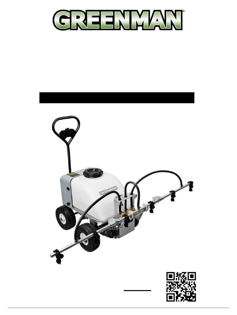
GREENMAN SPRAY HAWK CD30E-200 User manual

Greenman Golf & Turf Solutions •1028 4th St SW / Unit A • Auburn, WA 98001 • 253-333-3345 • GreenmanGolfTurf.com
SPRAY HAWK
FOLDING BOOM SPRAYER
MODEL CD30E-200
OPERATOR’S MANUAL

CD30E-200 SPRAYHAWK OPERATOR’S MANUAL
Greenman Golf & Turf Solutions • 1028 4th St SW / Unit A • Auburn, WA 98001 • 253-333-3345 • GreenmanGolfTurf.com
Technical Information
Dimensions: 48”L x 76”W x 36”H
Weight: 29 lbs.
Nozzle Type: Tee Jet XR8004 / Flat Fan Style
Key Product Features
Identification of Main Components, Fasteners and Assembly Parts
Folding Booms
Locator Screw
Spray Gun,
Adjustable Handle &
Pressure Gauge
3-Way Valve
Adjustable Height
Rear Wheel

CD30E-200 SPRAYHAWK OPERATOR’S MANUAL
Greenman Golf & Turf Solutions • 1028 4th St SW / Unit A • Auburn, WA 98001 • 253-333-3345 • GreenmanGolfTurf.com
Assembly Instructions
Tools Needed
- 10/12/14/17mm wrenches or two medium
adjustable wrenches
- Standard Flat Head Screw Driver
Step 1 –Handle
Attach handle to the
upper frame using
the quick release
clamp.
NOTE: All clamps will need
to be adjusted / rotated to
achieve adequate tightness
to secure components in
position.
Step 2 –Upper & Lower
Frame Attach the upper
frame to the
lower frame
using two (2)
8x50 bolts with
washers and
nuts.
Step 3 –Rear Wheel
Insert the rear wheel
assembly into the upper
frame, align set screw and
fasten using a quick-release
clamp on each side.
Step 4 –Front Wheels
Install the front wheels on to
the axles of the lower frame
and fasten using two (2)
6x15 hex head bolts with washers.
Step 5 –Axle Braces Install the axle braces
on to the axle using
two (2) 8x45 bolts
with washers and
nuts, and on to the
upper frame using the
8x45 bolt with
washers and nut.
Step 6 –Spray Gun & Hose Assembly
Mount the spray gun on
the upper frame using
two (2) 6x16 bolts with
washers. Route the main
hose through the folded
boom brace as shown
and secure with the
clamp assembly.
Step 7 –Spray Booms
Attach the spray booms on
the lower frame using the
two (2) 10x50 bolts with
washers and nuts.
Move the booms to
folded positon and
install the boom springs
using a standard
screwdriver to extend
and connect.
Connect boom hoses to
valve assembly and secure
to the frame using a tie
strap.
Step 8 –Speedometer (Optional)
Note the location of the
sensor magnet on a
front wheel and attach
the speed sensor to the
axle within 5mm (1/4”)
using tie strap.
Route the wire and
display screen to the
desired mounting location.

CD30E-200 SPRAYHAWK OPERATOR’S MANUAL
Greenman Golf & Turf Solutions • 1028 4th St SW / Unit A • Auburn, WA 98001 • 253-333-3345 • GreenmanGolfTurf.com
SAFETY PRECAUTIONS
These precautions are provided to help ensure operator,
bystander and environmental safety.
The GREENMAN Spray Hawk is designed for use by professional grounds care maintenance
staff with experience in applying chemical agents. Never allow children or untrained individuals
to operate or be in close proximity of the unit while in operation.
Persons engaged in the handling, preparation or application of chemicals must follow accepted
practices to insure the safety of themselves and others.
Wear protective clothing including: gloves; hat; respirator, eye protection and skin covering
suitable for protection from chemicals being used. Bathe thoroughly after any exposure to
chemicals, giving particular attention to eyes, nose, ear and mouth.
Clean equipment and materials in accordance with employer, municipal and state regulations,
using only approved areas and drains.
Dispose of chemicals and rinse solutions by approved and legal methods.
Provide methods and materials for operators to wash eyes and hands immediately during the
spraying process.
Provide methods and materials for control, safe dilution & neutralization of chemical spills
during preparation, spraying, transporting and clean up. Always have a representative material
safety data sheet (MSDS) on hand for chemicals being used.
GENERAL OPERATING INSTRUCTIONS
The liquid supply line from the pumping system attaches at the ½” NPT inlet coupling swivel on
the shut off valve. The connected pumping system should have a pumping capacity of at least
7 GPM at 40 psi when using the 8004 tips. A good in-line strainer and a pressure regulator
system capable of pressure adjustment below 125 psi, (the maximum operating pressure).
Set the desired spray height, with the handle held in the operating position. The usual tip
height is approximately 9-10” above the ground when using the 80 degree tips.
Note: The number of TeeJet flat spray nozzle tip indicates its pattern angle and its capacity at
a pressure of 40 psi. For example, the 8004 tips as supplied standard on the Greenman Spray
Hawk have an 80 degree spray pattern as indicated by the first two numbers. The last
numbers indicate the capacity of the tips in GPM at a pressure of 40 psi (0.4 GPM). The XR
designation indicates extended range with spray pattern distribution over a wide range of
pressure (15-60 psi). For more information on TeeJet nozzles, visit their web site at
www.teejet.com.

CD30E-200 SPRAYHAWK OPERATOR’S MANUAL
Greenman Golf & Turf Solutions • 1028 4th St SW / Unit A • Auburn, WA 98001 • 253-333-3345 • GreenmanGolfTurf.com
GENERAL OPERATING INSTRUCTIONS (CONTINUED)
The amount of material applied by the Spray Hawk is a combination of the following factors:
•Spraying speed.
•Differing capacity nozzle tips.
•Nozzle tip spacing.
•Spraying pressure.
Additionally, factors such as material specific gravity (heavier or lighter), chemical/water
concentration ratio, worn or malfunctioning components such as worn jets or clogged screens,
and changes in pressure can all cause variations in the rate of application.
Spraying pressure is usually more important in relation to the type of application and the type
of tip used, than to the rate of application. Since nozzle flow rate is almost proportional to the
square root of pressure, it would take 4 times the amount of pressure to double the application
rate. Usually boom application pressures will range from 15 to 60 psi with extended range tips.
The average droplet size of the sprayed material as it leaves the nozzle is smaller as pressure
is increased. A large capacity nozzle tip generally produce larger spray droplets than a smaller
capacity tip. Depending on the material being applied, higher pressure may be desired to
produce a finer spray. Alternatively, the chemical may not require finer droplets and higher
pressure may result in unwanted spray drift and uneven coverage.
Fundamentally, the rate of application can be changed to an extent by changing pressure.
However, a significant change is best achieved by installing a different capacity set of nozzle
tips, or altering the spraying ground speed.
Helpful Tips:
•Liquid loses pressure due to friction as it travels through the hose, from
1 to 3 PSI for each foot (30 cm) of hose length.
•Always be alert to the possibility of a plugged or damaged nozzle. Check nozzles out-
put periodically to ensure flow is consistent and even amongst all nozzles.
•Always test the spray hawk using clean water, on a surface where the spray pattern is
visible (such as a parking lot), prior to applying chemicals to the actual surface to be
treated.
•Serious misapplication may result if the proper calibrations and mixtures are not
identified prior to use.

CD30E-200 SPRAYHAWK OPERATOR’S MANUAL
Greenman Golf & Turf Solutions • 1028 4th St SW / Unit A • Auburn, WA 98001 • 253-333-3345 • GreenmanGolfTurf.com
PARTS INFORMATION
1. INLET / SPRAY GUN / HOSE CONNECTION

CD30E-200 SPRAYHAWK OPERATOR’S MANUAL
Greenman Golf & Turf Solutions • 1028 4th St SW / Unit A • Auburn, WA 98001 • 253-333-3345 • GreenmanGolfTurf.com
2. UPPER SUPPORT / FRAME

CD30E-200 SPRAYHAWK OPERATOR’S MANUAL
Greenman Golf & Turf Solutions • 1028 4th St SW / Unit A • Auburn, WA 98001 • 253-333-3345 • GreenmanGolfTurf.com
3. LOWER SUPPORT / FRAME / WHEELS

CD30E-200 SPRAYHAWK OPERATOR’S MANUAL
Greenman Golf & Turf Solutions • 1028 4th St SW / Unit A • Auburn, WA 98001 • 253-333-3345 • GreenmanGolfTurf.com
4. SPRAY BOOM

CD30E-200 SPRAYHAWK OPERATOR’S MANUAL
Greenman Golf & Turf Solutions • 1028 4th St SW / Unit A • Auburn, WA 98001 • 253-333-3345 • GreenmanGolfTurf.com
SPEEDOMETER
This optional accessory provides the ability to track walking speed. It’s
a bicycle speedometer and includes many different programmable
functions, but following are steps for setting it up to provide the
speed readout for the Spray Hawk….
SPEEDOMETER PROGRAMMING (IF NEEDED)
1. Insert the battery
2. Set tire size. NOTE: this setting is for the
tire circumference and needs to be entered
as millimeters. The SPRAY HAWK tire
diameter is 11.75 inches and is a
circumference of 37 inches, which when
converted is 940 millimeters.
a. Press right lower button. Flashing
number will change, and continue to
“0”
b. Press the left button to set and
move to the next digit to the left.
c. Repeat steps “a” and “b” to
complete the entry of “0940”
d. If you need to start over, remove
and reinstall the battery.
3. Set miles / kilometers per hour
a. Press the right button to switch
from km to m
NOTE: the remaining settings are bicycle / rider related features.
SPEEDOMETER SENSOR / SENSOR MAGNET / MOUNTING
It not already installed, a hole needs to be added to a wheel cover to accommodate the speedometer
sensor magnet. Once the magnet is added and the wheel is installed (either side / magnet on the
inside), place the sensor on the axle, space within 3/16” (5mm) from the magnet and secure with tie
straps. The computer unit can be located as desired and extra tie straps are included to secure it.

CD30E-200 SPRAYHAWK OPERATOR’S MANUAL
Greenman Golf & Turf Solutions • 1028 4th St SW / Unit A • Auburn, WA 98001 • 253-333-3345 • GreenmanGolfTurf.com
LIMITED WARRANTY STATEMENT
Greenman Golf & Turf Solutions hereby warrants the Greenman Walk-Behind Boom Sprayer model CD30E-200
to be free from defects in material or workmanship for a period of ninety (90) days after purchase. This warranty is
limited to repair or replacement by Greenman Golf & Turf Solutions of such parts as appear upon inspection, to
be defective in material and/or workmanship.
The above warranty is extended only to the first end user, and no warranty is made nor authorized to be made
assignable on resale. Greenman Golf & Turf Solutions makes no warranty with respect to replacement parts not
manufactured or sold by it. Such parts are subject to the warranty policy of their respective manufacturers. To
obtain performance of any obligation under this warranty for failure during the applicable warranty period, contact
Greenman Golf & Turf Solutions at: 1028 4th Street SW, Building A, Auburn WA 98001, (253) 333-3345.
Warranty coverage is conditioned upon the first end user furnishing Greenman Golf & Turf Solutions or its
Authorized Service Dealer with adequate written proof of the original purchase date. Greenman Golf & Turf
Solutions reserves the right to inspect the claimed defective part(s) to determine if the malfunction is the result of
a defect covered by this warranty. This warranty will cover only defects arising under normal usage, and shall not
apply, nor will Greenman Golf & Turf Solutions assume any responsibility, if the failure was caused by the
following:
1. Misuse, abuse, or negligence.
2. Accident or physical damage.
3. Repairs made by unauthorized parties and/or with unauthorized parts.
4. Improper unit set up or altered components.
5. Failure to operate or maintain the unit in the manner specified by the owner’s manual.
Inspection, service, cleaning and adjustments to normal maintenance items such as spray nozzles, diaphragms,
etc. are not considered the responsibility of Greenman Golf & Turf Solutions under this warranty.
THIS LIMITED WARRANTY IS IN LIEU OF ALL OTHER EXPRESS WARRANTIES, OBLIGATIONS, OR
LIABILITIES. ANY IMPLIED WARRANTIES, OBLIGATIONS, OR LIABILITIES INCLUDING, BUT NOT LIMITED
TO, ANY IMPLIED WARRANTY OF MERCHANTABILITY OR FITNESS FOR A PARTICULAR PURPOSE
SHALL BE LIMITED IN DURATION TO THE APPLICABLE WARRANTY PERIOD FOR THE FIRST END USER.
ANY ACTION FOR BREACH OF ANY WARRANTY HEREUNDER INCLUDING, BUT NOT LIMITED TO, ANY
IMPLIED WARRANTY OF MERCHANTABILITY OR FITNESS FOR A PARTICULAR PURPOSE MUST BE
BROUGHT WITHIN A PERIOD OF SIX MONTHS FROM THE END OF THE APPLICABLE WARRANTY
PERIOD.
Some states do not allow limitations on how long an implied warranty lasts, so the previously stated limitations
may not apply to you. No agent, representative, dealer, or employee of Greenman Golf & Turf Solutions has the
authority to increase or alter the obligations of this warranty.
IF THE PRODUCT IS USED PRIMARILY IN A COMMERCIAL OR RENTAL APPLICATION, GREENMAN GOLF
& TURF SOLUTIONS WILL NOT BE LIABLE FOR GENERAL DAMAGES INCLUDING BODILY INJURIES,
EXCEPT AS SET FORTH ABOVE, OR FOR INCIDENTAL OR CONSEQUENTIAL DAMAGES INCLUDING, BUT
NOT LIMITED TO, LOSS OF USE, LOSS OF PROFITS, LOSS OF PRODUCTION, EXPENSE OF SUBSTITUTE
EQUIPMENT OR OTHER COMMERCIAL LOSS OR DAMAGE. THE SAME LIMITATIONS SHALL APPLY TO A
PRODUCT USED FOR CONSUMER PURPOSES WITH RESPECT TO ALL NON-PERSONAL INJURY,
GENERAL INCIDENTAL AND CONSEQUENTIAL DAMAGES.
Some states do not allow the exclusion or limitation of incidental of consequential damages, so the above
limitation or exclusion may not apply to you. This warranty gives you specific legal rights, and you may also have
other rights which vary from state to state.
Table of contents
Other GREENMAN Paint Sprayer manuals
Popular Paint Sprayer manuals by other brands

Gregson-Clark
Gregson-Clark SPREADER-MATE SM-B Operator's manual

Central Pneumatic Professional
Central Pneumatic Professional 43430 Assembly and operating instructions

Scientific
Scientific 207 R01 Installation operation and care

Titan
Titan Impact 1040T quick start guide

pela tools
pela tools 531933 manual

DeVilbiss
DeVilbiss AGX-552 Operation manual