EXCELSENSE ToughEye-1700 User manual

ToughEye-1700™
User Manual, V1.3

Table of Contents
Table of Contents 1
Overview 3
Important Safety Instructions 3
Warning 3
Caution 4
Compliance 5
Electromagnetic Compliance Information 5
USA 5
Canada 5
Europe 5
Australia/New Zealand 5
Specifications 6
Ordering Options 8
Accessories 9
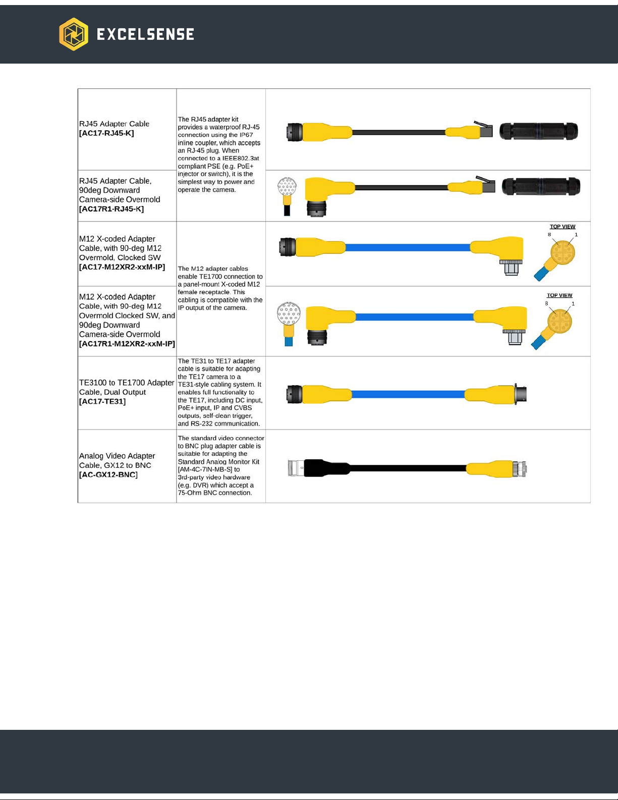
Cable Harnesses 9
Part Number Guide 9
Cables List 10
Cable Accessory Detail - Sealed Inline RJ45 Coupler 12
Power Supplies 12
DC Source - 24VDC Supply 12
PoE+ Source - IEEE802.at Compliant PSE 13
Junction Boxes 14
Standard Boost Box 14
Self-Cleaning Trigger Button Box 14
Video Monitor Kits 15
7” Standard Series 4ch Monitor Kit [AM-4C-7IN-S] 15
7” Extreme Series 4ch Monitor Kit [AM-4C-7IN-X] 15
Mounting Accessories 15
ToughEye-1700™ Standard Bracket 15
Field Welding Bracket Options 17
System Installation 18
Configuration Selection 18
IP Camera Configurations 18
Network Configuration A-1 18
Option 1 19
1

Option 2 19
Network Configuration A-2 20
Option 1 20
Option 2 21
Analog Camera Configurations 21
Analog Configuration B-1 21
Analog Configuration B-2 22
Interfacing the ToughEye-1700™ 24
Powering the ToughEye-1700™ 24
PoE+ Power Source 24
DC Power Source 25
Triggering the ToughEye-1700™ 26
Manual Trigger 26
Manual Trigger when using PoE+ 27
Remote Manual Trigger using Web Interface 27
Manual Trigger using External Button 28
Automatic Trigger 28
ToughEye-1700™ Controller Module Communication 29
Technical Information 30
ToughEye-1700™ Thermal Variants 30
Standard-Thermal Variant 30
Integrated High-Power LED Variant 30
Background 30
LED Illumination Control 30
Specifications 31
Active Illumination Control Curves 31
DC Power Source 31
PoE+ Power Source 31
Spectral Distribution 32
Radiation Pattern Characteristization 32
Optical Module - Network Interface 33
ToughEye-1700™ Dimensions 34
2
Overview
Patented ClearSightTM technology actively and automatically clears the field of view of the
camera without any regular maintenance. The technology is effective against oil, grease, mud,
and various other industrial contaminants. ClearSightTM enables cameras to self-clean — in
most cases, for several years — eliminating the need for access and regular maintenance.
The ToughEye-1700TM camera is equipped with ClearSightTM technology. The system requires
nothing more than conventional electrical connections; its rugged, self-contained design
eliminates the need for fluid tanks, hoses, compressors, and pumps.
Important Safety Instructions
Warning
1. This is an ITE class A device. In a domestic environment this product may cause radio
interference in which case the user may be required to take adequate measures.
2. This is an IEEE 802.3at compliant device equipped with Layer 1 (hardware interface)
PoE+ detection and classification hardware. If using power-over-ethernet, only connect
to IEEE 802.3at compliant power sourcing equipment (PSE) devices with all
software-layer (e.g. LLDP, CDP, etc.) communications disabled on the port, which should
be preset to deliver up to 30W of guaranteed power. Failure to meet these requirements
may cause faults that can lead to permanent damage to the ToughEye-1700™’s internal
electronics.
3. All electrical connections must be made by qualified personnel in accordance with local
and national electrical codes and regulations. Electrical power is not to be applied to
conductors at any point during the installation and connection process.
4. Connecting the ToughEye-1700TM cable incorrectly poses a risk of injury due to electric
shock to the user, and can damage the device.
5. Damaged or faulty cable connections may leave electrical conductors bare and/or
short-circuited. Extra care must be taken during cable installation in order to avoid this
scenario. In such a circumstance, do not attempt to handle conductors before removing
power.
6. The ToughEye-1700™ lens is made with hardened glass. The user should take
necessary precautions when handling the system. If excessive, direct force is induced,
the glass may break, causing system failure and potential injury to the user.
3

Caution
1. Alterations or modifications carried out without appropriate authorization may invalidate
the user’s right to operate the equipment. Refer to the ExcelSense Hardware Terms and
Conditions, found here, for more information.
2. If powering the device using DC voltage, a Class 2 24VDC 3A power supply is
recommended to ensure the best picture quality and stable operation. With its internal
protection and regulation, ToughEye™ can be operated with an unregulated 24VDC
power supply. In this scenario, voltage fluctuation limits will be dependent on setup.
Refer to the Electrical Specifications section on ToughEye-1700™ operational limits.
3. If powering the device using power-over-ethernet (PoE), only connect to IEEE 802.3at
compliant power sourcing equipment (PSE) devices with all software-layer (e.g. LLDP,
CDP, etc.) communications disabled on the port, which should be preset to deliver up to
30W of guaranteed power. Failure to meet these requirements may cause faults that can
lead to permanent damage to the ToughEye-1700™’s internal electronics.
4. Only use fully-compatible cabling, as recommended by ExcelSense representatives, to
connect ToughEye-1700™ cameras in your application. Failure to do this may cause
unintended behaviour and permanent damage.
5. This device is not compatible with ToughEye-3100™ cabling. If replacing a
ToughEye-3100™ product with this device, new cabling or an appropriate ExcelSense
adapter cable must be used with this device. Consult your ExcelSense representative for
more information.
6. It is recommended that ToughEye-1700™ be used with the ExcelSense Analog Monitor
when analog view is required. However, ToughEye-1700™ may be used with any analog
monitor (NTSC or PAL) using a 75Ω impedance level coaxial cable.
7. Do not attempt to disassemble ToughEye-1700™ in order to access internal
components. Consult ExcelSense for technical support as required.
8. Never face the ToughEye-1700™ directly towards the sun or any bright or reflective light,
which may cause smear on the picture and possible damage to the CCD.
9. Do not remove the ToughEye-1700™ label containing P/N and S/N information for
warranty service.
10. Never expose ToughEye-1700™ to conditions outside those specified in the
Specifications section. Doing this can cause permanent damage to the device.
11. Damaged ToughEye-1700™ equipment must be replaced through an ExcelSense
representative. Failure to do this may cause incompatibilities and permanent damage to
the system.
12. Always clean the ToughEye-1700™ lens by performing cleaning cycles (see Triggering
the ToughEye-1700™ section for details). Do not clean the lens manually.
ToughEye-1700™ may also be pressure washed as an alternative.
4

Compliance
Electromagnetic Compliance Information
USA
The ToughEye-1700™ and its custom peripheral hardware, produced and sold by ExcelSense
Technologies, have been tested and found to comply with the applicable regulatory
requirements and limits for electromagnetic compatibility (EMC) for a Class A device, pursuant
to part 15 of the FCC Rules. Operation is subject to the following two conditions:
(1) This device may not cause harmful interference, and
(2) this device must accept any interference received, including interference that may cause
undesired operation
These limits are designed to provide reasonable protection against harmful interference when
the equipment is operated in a commercial environment. This equipment generates, uses, and
can radiate radio frequency energy and, if not installed and used in accordance with the
instruction manual, may cause harmful interference to radio communications. Operation of this
equipment in a residential area is likely to cause harmful interference in which case the user will
be required to correct the interference at his/her own expense.
Please follow the recommended installation guidelines as expressed in this manual when
installing this device and its peripherals and cabling. Any changes or modifications made to the
recommended system architecture or installation instructions could result in electromagnetic
non-compliance, and so may void the authority granted to the user by the FCC to operate this
equipment.
Canada
This Class A digital apparatus complies with CAN ICES-3. Cet appareil numérique de la classe
A est conforme à la norme NMB-003 du Canada.
Europe
This digital equipment fulfills the requirements for RF emissions according to the Class A limit of
CISPR 32 / EN 55032.
Australia/New Zealand
This digital equipment fulfills the requirements for RF emissions according to the Class A limit of
AS/NZS CISPR 32.
5

Specifications
CAMERA
Image Sensor
2.1 MP
Effective Pixels
1920 (H) x 1080 (V)
Horizontal FoV
Approx. 80°, 100°
Vertical FoV
Approx. 50°, 67°
Min Illumination
Color: 0.001 Lux @ (F1.2, AGC ON)
B/W: 0.0001 Lux @ (F1.2, AGC ON)
Wide Dynamic Range
True WDR (>120dB)
IP Video
H.265 (1920x1080) | H.264 (1920x1080) | MJPEG (1280x720)
Streaming Capability
Stream 1: 1920×1080/1280×720 @50/60fps
Stream 2: D1/VGA/640×360/CIF/QVGA @25/30fps
Stream 3: VGA/CIF/QVGA @25/30fps
Network
IPv4/IPv6, 802.1x, HTTP, HTTPS, TCP/IP, UDP/IP, RTSP, DHCP, NTP,
RTCP/RTP, PPPoE, SMTP, DNS, UPnP, FTP, ARP, SNMP
ONVIF
Profile S, Profile G
Recording
128GB max storage - Continuous, Motion, Pre/Post Alarm
Analog Video (CVBS)
720x486 (NTSC), 720x576 (PAL)
GENERAL
Dimensions
102mm dia x 178mm [4in dia x 7 in]
Weight
3.0kg [6.5lb] - 4.3kg [9.5lb] with Bracket and Sunshield
Power
18~32VDC or PoE+ (IEEE802.3at, Class 4)1
Clean Cycle
Automatic: Configurable Timer or Schedule-Based
Manual: Network Command or Electrical Trigger
Thermal
-40°C to 60°C (operation and storage)
IP Rating
IP69
Vibration
11g (JIS-D-1601-1995)
Luminosity
(Visible LED Variant)
1500 lumens (typical output at 20°C)
Max Lux
3800 lux (at distance of 30cm, typical output at 20°C)
Color Temperature
4000K
ELECTRICAL
Parameter
Min
Typ
Max
Input Voltage, VIN (DC port)
18V
24V
32V
Input Voltage, VIN (PoE+ port)
36V2
57V
2PoE+ VIN (min) is 42.5V at the camera, as per IEEE802.3at. The camera will engage its PoE undervoltage
protection at 36V.
1ToughEye-1700™ utilizes a hardware-layer PoE+ classification protocol. It is not compatible with any
software-layer protocols, such as LLDP or CDP.
6

Power Consumption, PIN
5W (Idle)
25W (Heating)
Input Protection (DC port)3
Clamping Voltage, VC
116V
Peak-pulse Power, PPP
6.4kW (28ms pulse duration)
Peak-pulse Current, IPP
35A
Overvoltage Lockout, VOVLO
Engage lockout (rising)
33.3V
Disengage lockout (falling)
33.0V
Undervoltage Lockout, VUVLO
Engage lockout (falling)
17.0V
Disengage lockout (rising)
19.0V
Overcurrent Threshold, IOVC
3A (internal PTC fuse)
Reverse-Polarity, VRVP
[Pulse defined by ISO 7637-2]
Input Protection (PoE+ port)
Input crow-bar protection
(protects against external cabling
surge events)
[Defined by: IEC 61000-4-5,
TIA-968-A/B, ITU K.20/21
Enhanced Level]
Max Cable Length2, LMAX
40m (DC), 100m (PoE+)
Trigger Input, VTRIG
0V / Open
0V (internal
pull-down)
VIN
3Tested as per ISO 16750-2. Designed for complete load isolation during damaging input conditions.
7

Ordering Options
TE17 - ToughEye-1700™ camera
Lens Angle (customization available)
080 - Approx. 80° Horizontal FoV
100 - Approx. 100° Horizontal FoV
Temperature Rating
X- Extreme: -40oC to 60oC
Environmental Resistance
S- Standard Corrosion Resistant
C- Highly Corrosion Resistant
Camera Type
D- Dual: IP / Analog Camera
Illumination
N- None
V- Visible LEDs
Cycle Rating
S- Standard Cycle Rating 40,000 cycles
Hazardous Locations Certification
NR - Not Rated for Explosive Environments
Local Video Storage
N- Not Loaded
L- Loaded Onboard Video Storage
L-Capability (128GB)
8

Accessories
The following lists the standard accessories available for ToughEye-1700™ installations.
Cable Harnesses
Part Number Guide
9

11
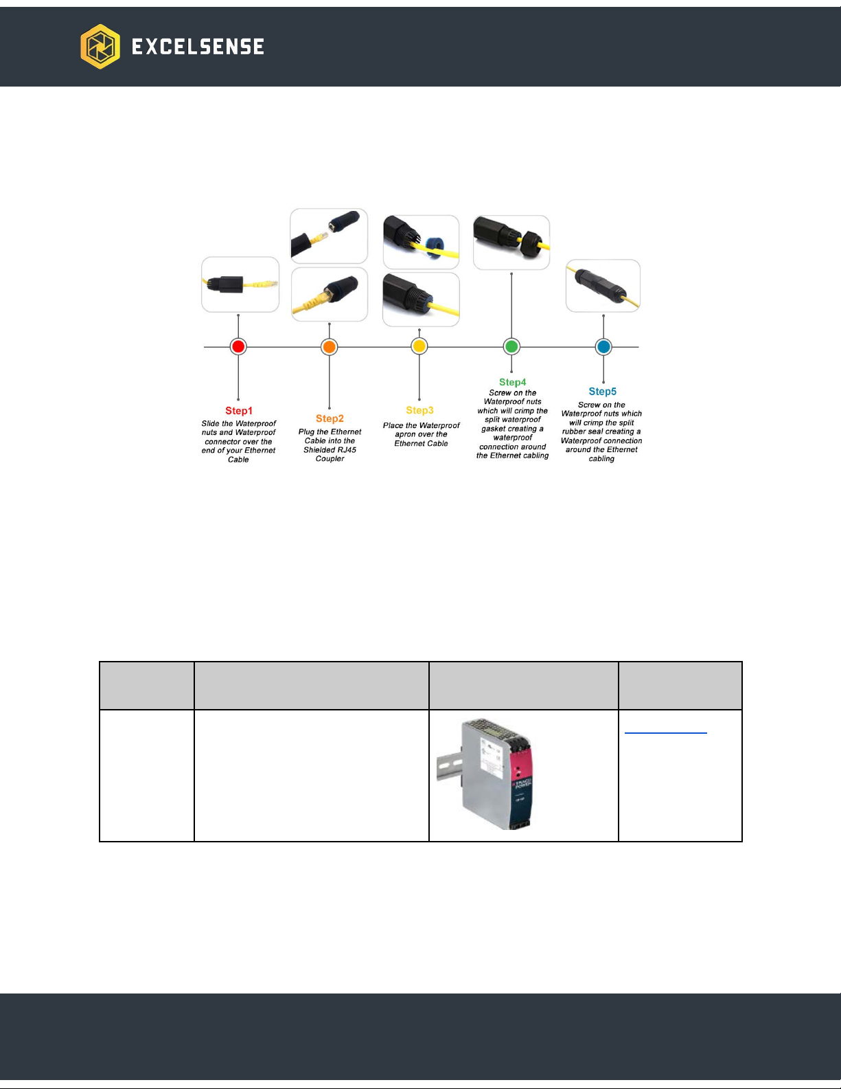
Cable Accessory Detail - Sealed Inline RJ45 Coupler
The sealed in-line RJ45 female-to-female coupler is included in the PoE adapter cable kit
[AC17-RJ45] to achieve an IP67 dust/water rated, network cable connection.
Power Supplies
DC Source - 24VDC Supply
In applications where only AC power is available, the following AC-DC converter can be used to
supply the ToughEye-1700™ and optionally an external monitor with 24VDC.
Part
Number
Description
Preview
Datasheet
PSU-24V-12
0W-DIN
AC to DC power supply, 24V
output, 120W, 110VAC to
260VAC
TIB 120-124
12

PoE+ Source - IEEE802.at Compliant PSE
In applications where the PoE+ power method is preferred, it is important to ensure the correct
PoE power source equipment (PSE) class level is selected. The ToughEye-1700™ is a class 4
powered device (PD), meaning it is rated to draw up to 25.5W, as per the IEEE802.at standard.
For this device, a class 4 PSE compliant with the IEEE802.3at standard and rated to provide at
least 30W to the ToughEye-1700™ is required. The recommended options are shown below.
Part
Number
Description
Preview
Datasheet
INJ-POE-S
Commercial grade PoE+ injector,
ideal for areas protected from the
environment, and benchtop
testing and demonstration,
Input:100-240V AC
TPE-115GI
(v2.1)
INJ-POE-N
Industrial grade PoE+ injector,
suitable for field deployment with
a wide temperature range -40C
to 65C, Input:10-30 VDC
POE-24
13
Junction Boxes
Standard Boost Box
The standard ToughEye-1700™ Boost-Box is intended for wiring a single ToughEye-1700™
camera to a mobile vehicle monitor system. Additionally, the Boost-Box extends the input
voltage range making it suitable for 12V applications. Please refer to the boost box
documentation, found here, for details on suggestion applications, technical specifications, and
in-field wiring instructions.
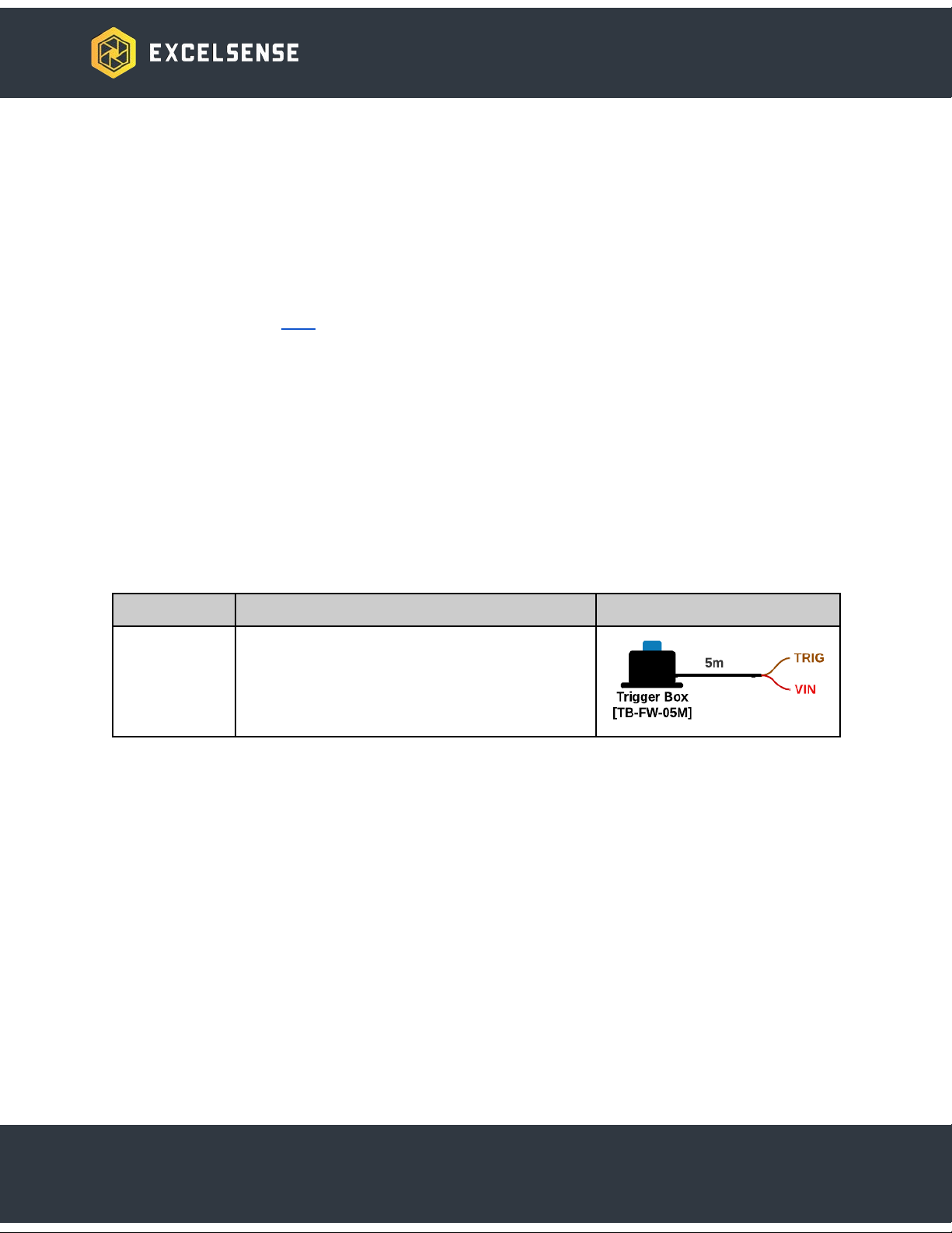
Self-Cleaning Trigger Button Box
The ToughEye-1700™ can be triggered to clean its lens through many different ways, one of
them being through the hardware trigger method. This method involves accessing the trigger,
power, and ground signals of the electrical system in order to switch the trigger signal.
A simple way of accomplishing this is through the self-cleaning in-cab Trigger Button Box.
Part Number
Description
Preview
TB-FW-05M
Self-Cleaning in-cab trigger button, black
aluminum with blue button, with mounting
flange, IP65 rated, with 5m open-ended cable
14

Video Monitor Kits
7” Standard Series 4ch Monitor Kit [AM-4C-7IN-S]
The Standard Monitor Kit features a rugged 4-channel 770 series monitor, which supports
12VDC and 24VDC systems. When connected to the ToughEye-1700™ analog video output
connector, it produces a clear CVBS video.
Please refer to the Standard Monitor Kit Reference Manual here for more detailed technical
information such as the recommended wiring diagram as well as ordering information.
7” Extreme Series 4ch Monitor Kit [AM-4C-7IN-X]
The Extreme Monitor Kit features a rugged 4-channel 970 series monitor, which supports
12VDC and 24VDC systems, has a -40°C ~ 70°C industrial temperature rating, and has 10G
and 100G mechanical vibration and shock ratings respectively. When connected to the
ToughEye-1700™ analog video output connector, it produces a clear CVBS video.
Please refer to the Extreme Monitor Kit Reference Manual here for more detailed technical
information such as the recommended wiring diagram as well as ordering information.
Mounting Accessories
The following accessories are available for mounting the ToughEye-1700™.
ToughEye-1700™ Standard Bracket
The ToughEye-1700™ Standard Bracket is included as it is the default bracket in most
ToughEye-1700™ installations.
The bracket should first be mounted to a suitable horizontal support with sufficient strength. The
camera ships with high strength, 3/8”-16, 1.25” long bolts, suitable for mounting to plates up to
0.625” thick. If mounted to a thicker support, suitable Grade 8 bolts should be sourced. The
standard bolt and nylon insert lock-nut can be installed using 9/16” wrenches or sockets.
15

Mounting pattern and bolt details
If the camera is mounted to a vertical surface a horizontal bracket [MB-TE-WB] can first be
welded to the vertical surface, in order to provide a suitable mounting point.
With the bracket mounted the camera can be installed. Start by placing the camera within the
bracket and loosely attaching it at all 4 mounting points. Be sure to use the included split lock
washers:
Camera bolt installation ordering
Rotate the camera to the desired orientation. Note that the standard bracket accommodates
mounting angles from 0° (horizontal) to down by 80°. With the camera at the desired orientation,
tighten the bolts using a 7/16” wrench or socket. Bolts should be tightened to 8.5 Nm [6.3ft-lb].
16

Field Welding Bracket Options
Part Number
Description
MB-TE-WE
Field Welding Bracket, ToughEye Compatible.
Suitable for welding to existing horizontal or vertical surfaces when bolting
is not an option.
MB-TE-DW-K
Field Welding Bracket Damping Kit, ToughEye Compatible.
Suitable for welding to existing horizontal or vertical surfaces in
high-vibration applications.
The image below shows the MB-TE-DW-K kit with the standard ToughEye-1700™ bracket
installed.
17

System Installation
Configuration Selection
IP Camera Configurations
The ToughEye-1700™ supports network and analog video streams. Selection of the appropriate
stream is an important consideration.
The network stream provides simpler connections, higher resolution video, and accessibility to
the stream from any device connected to the same network. We recommend using the
network stream in the following scenarios:
1. The stream must be viewed remotely | See Network Configuration A-1
2. The stream must be viewed on the equipment and an on-equipment display exists which
is powered by a computer (ie. Panel PC or Dispatch system) | See Network
Configuration A-1
It is important to note that IP video has inherent latency due to video compression. The
ToughEye-1700™ latency is tested at approximately 150ms , so only in applications where this
4
latency can be tolerated is the network stream recommended.
Network Configuration A-1
This configuration allows any shielded Cat-5e cable to be used to power and communicate with
the ToughEye-1700™ camera. No custom cabling is required to be routed, as the shielded
Cat-5e cable plugs into either the custom short adapter cable or the open end of the main cable
for plug and play functionality. See below for connection diagrams.
4Latency tested by directly plugging a short Cat-5e cable to a laptop and streaming 1080p H.264 video
onto the IP Cam Viewer 4 software at 30fps. Note that depending on the network environment, bit rate,
server specification, and viewing software, the measured latency may differ from this rating
18

Option 1
This option is the simplest configuration shown in the figure above and uses an endspan
IEEE802.3at (PoE+) compliant power sourcing equipment (PSE) to provide power to the
camera through the same shielded Cat-5e cable used for data transmission.
Option 2
This option is optimal for applications with existing network switches that are not IEEE802.3at
compliant. In this configuration, a midspan PoE+ injector can be used (see Accessories section
earlier in this document for ordering information) in-line between the switch and the camera as
shown above. The injector accepts a 12~24VDC or 110~260VAC input, depending on the
model, and supplies PoE+ power to the camera while also transmitting the data signals.
This configuration is designed to be simple to install and configure:
1. From an IEEE 802.3at compliant PoE+ PSE (power sourcing equipment) - either an
endspan switch or midspan injector - route a shielded Cat-5e or better cable to the
ToughEye-1700™. Ensure the routed cable is appropriately rated for your application
(temperature, ingress protection, ruggedness, etc).
2. Once the cable has been routed to within 1m of the camera, it can be plugged into the
waterproof Cat-5e adapter. For details on usage of the Cat-5e adapter please refer to
section Sealed In-line RJ45 Coupler.
3. The RJ45 Adapter Cable [AC17-RJ45] can now be plugged into the ToughEye-1700™
camera.
19
Table of contents


