Preparing the Unit for First Use 5Remove the terminal block.
Flip the main power switch to
the on position.
8Press to turn the unit on.
The current IP address of the unit will be
displayed when unit is ready.
Ensure that the unit’s main power
switch is in the off position.
WARNING
Ensure that you read and understand all the warnings and
installation information provided in the RTU-2 user guide before
proceeding.
2
Ensure that the unit is grounded properly.
4
Ensure all power is off or disconnected at the source.
3
Main power switch in off position
The LED will be green and steady
when unit is ready.
Understanding the LEDs (RTU-2 and RTUe-9110)
(RTU-2 unit only)
Green, steady: The unit is on.
Green, blinking: The unit is in Sleep or Hibernation mode.
Yellow: One of the unit’s fuses is blown.
Green, steady: The unit or the external switch is working properly and is ready.
Green, blinking: The initialization of the unit or the external switch is underway.
Yellow: Non-critical hardware error detected.
Red: Critical hardware error detected.
Connect one end of a network cable to the desired Ethernet port(s), and the other end to a network.
1
Once it is done, install the prepared
wires respecting the polarity.
OR
Connect the provided AC/DC power
adapter.
6
7
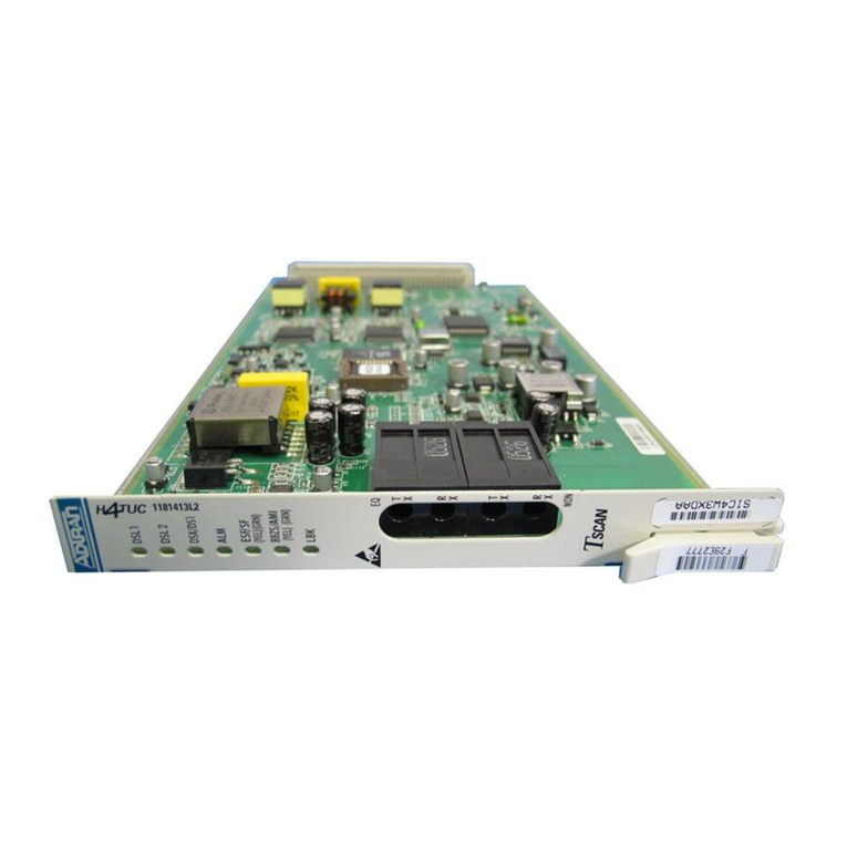
Inserting Modules
1Place the module horizontally so that the connector pins are at the back, and the protruding edges are
facing downwards.
CAUTION
To avoid damaging your unit, use it only with modules approved by
EXFO (refer to the unit’s technical specifications).
Connect the provided USB cable to the USB port (B type) located on the back panel of the switch.
Connecting RTUe-9110 External Switches to
Your Unit
1
2
USB cable
Connect the other end of the USB cable to one of the USB ports located on the back panel of the unit.
2Insert the protruding edges of the module into the grooves and push all
the way to the back.
Note: There is no need to turn off your unit before inserting
a module.
Turn the two retaining screws clockwise to secure the module in place.
Its faceplate should be flush with the front panel of the unit.
3
Ethernet (RJ-45) port
(for LAN/WAN connection)
Ethernet (RJ-45) management port
(for local access)
