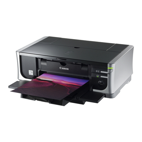
Exile FREEStyler DTS User manual

INSTALLATION AND
QUICK START GUIDE
Styler
FREE
Styler
DTS

FREEStyler DTS INSTALLATION AND QUICKSTART GUIDE
INSTALLATION
1.Unpacking & Setup
When recieving the FREEStyler it is important to inspect the crate for damage. If there is damage
please document and notify EXILE Technologies. If no damage is found proceed to the next step.
When lifting the FREEStyler out of the shipping box be careful to lift it out from the metal chassis
underneath. DO NOT LIFT FROM THE PLASTIC CASING OR PRINT CARRIAGE.
The FREEStyler should be installed on a sturdy, FLAT surface with no obstructions underneath as
the Y axis Printhead mechanism requires a minimum clearance underneath the FREEStyler of 25
mm (1.00”).
Adjust the height to ensure the FREEStyler is level using the adjustable feet on the four corners of
the chassis.
Check level on atbed.
Attach the power cable and USB cable as shown to the connections at the rear of the FREEStyler
as shown:
Connect the other end of the USB cable to the Windows PC where the FREEStyler Print Utility will
be installed (MiniFB).
You can now power on the FREEStyler.
USB POWER

2. FREEStyler Print Utility Software Installation
The FS Print Utility Software Installer is located on the SCREENMAKER RIP USB Dongle. A
copy can also be found on the CD/DVD inside the SCREENMAKER RIP/FS Print Utilty DVD Box.
On the PC that is to be attached to the FREEStyler (in the Screen room) RUN (or double click) the
MiniFB Installer application from either the CD or the USB Drive/Dongle and follow the step by
step prompts and instructions.
3. Loading a Screen Frame
FREEStyler uses Screen ‘Drums’ to ensure that the coated Screen mesh is raised above the
height of the Screen frame:
Once the Screen Drum has been positioned the Screen Frame can be loaded over it by sliding the
back of the frame under the rear clamp and then pushing the Screen frame up against the Tri-lock
pins on the rear left hand corner and left hand side. To achieve good registration from screen to
screen you must ensure that the outside of the Screen frame is pushed up fully against the Tri-lock
locating pins:
Lock down the front of the Screen using the front locking clamp. Depending on the size (height)
of the Screen frame it may be necessary to relocate the front clamp using the two black locating
screws:
DRUM
SCREEN FRAME
SILKSCREEN ON THE DRUM

4. Installing or Replacing a Print Cartridge
FREEStyler uses 1 ,2,3 or 4 ‘UV-Block’ Black Ink Cartridges arranged in an offset formation:
These are labelled T1, T2, T3 & T4 from the left to right. You will nd the current bank displayed
(T-?) on the control panel on the front right side of the FREEStyler. Make sure to place cartridge in
the correct bank before checking cartridge “in” or “out”.
Upon the initial startup the FREEStyler will give you the opportunity to install new cartridges.
If print cartridges are already installed select ‘E’ on the LED touch screen on the front of the
FREEStyler.
An exclamation point (!) will appear warning when cartridges are low and need to be replaced.
You can also install (or remove) a cartridge by launching the
MiniFB (FREEStyler) Print Utility...
This can be found on the bottom right of the Windows Screen
where the hidden icons reside:
Click on the Exile icon and select ‘Heads’
Then select ‘Change Heads’.
This will move the print carriage in position to
change the print cartridges out.
Note: Make sure you are on the correct bank before replacing
any cartridge. ie: T1, T2 etc. In this example T1 is selected:
Use the >> button to select different cartridges:
Pres ‘OK’ once you have the correct cartridge position selected:
Colour Banks KMCY
(DTG Mode)
T1 T2 T3 T4

Place the cartridge on the green cartridge reader, an acceptance bleep will sound, then insert the
cartridge into its slot:
Press ‘OK’ on the LED touch screen to complete the tting of the cartridge, a bar will be displayed
on the green cartridge reader to show the cartridge has been accepted and will indicate the ink
level in that cartridge.
You can repeat this process for installing additional cartridges... T2, T3 etc.
Normally for Computer to Screen CtS/DTS operation a maximum of 2 cartridges (T1 & T2) are
recommended.
After installation FREEStyler will perform a head wipe and the cartridge properties are displayed in
the MiniFB Utility menu:
Once installed you can check the cartridge
is ring ok with the ‘Nozzle Test’ from the
‘Heads’ menu:
Press OK from the FREEStyler LED touch
screen to start the print:
The Nozzle Test should look like this:

If you are installing more that one print cartridge a Horizontal & Vertical alignment test should also
be performed.
Tape some paper or ink jet lm on to a spare Screen frame to run these tests as they may need to
be run multiple times to achieve optimum print quality.
HORIZONTAL ALIGNMENT TEST
Use the FS Print Utility to select this option from the ‘Alignment’ Menu:
This shows the relative horizontal position of the 4 print heads (T1,T2,T3 & T4) relative to the rst
head > T1
This can be adjusted in the software. Enter the value(s) into the Print Utility that show the straight-
est line on the HORIZONTAL ALIGNMENT TEST Printout:

VERTICAL ALIGNMENT TEST
Use the FS Print Utility to select this option from the ‘Alignment’ Menu:
This shows the relative vertical position of the 4 print heads relative to the rst head > T1.
This requires a mechanical adjustment of the print heads. T2,T3 & T3 have a screw adjustment on
the front of each head which can be turned clockwise (CW) or counter-clockwise (CCW) as re-
quired. Look for the straightest line. A quarter turn equivalent to approx + or – 4 on the VERTICAL
ALIGNMENT TEST printout:

5. Printing an Image File (.prn)
Print les (.prn les) have to be Ripped rst in SCREENMAKER RIP and then printed via the
MiniFB (FREEStyler) Print Utility. This allows the SCREENMAKER RIP to be installed in an
Artroom or Design area independently of the FREEStyler.
The MiniFB Print Utility should be installed on the PC in the Screen room connected to the
FREEStyler.
There are several test print les (.prn les) located on the Installation CD as well as on the
SCREENMAKER USB Drive/Dongle.
To print a le select ‘Single Print from le’ or ‘Single Print from list’ from the MiniFB ‘Print’ menu:
Then Press OK from the FREEStyler front panel
menu to start the print:
To check progress double click on the ‘E’ EXILE icon:
Progress will display in this window:

You can create a queue of les to print by importing them into the MiniFB Print Utility using the ‘+’
Add File button as shown:
Similarly les can be deleted from the list using the ‘X’ Delete button.
The les will appear in print order in a list in the left hand window. They can then be printed one
at a time using the ‘Multiple print’ option. Each le will be printed in order once the ‘OK’ buton is
pressed on teh FREEStyler LED Touch Screen. After each print is nished the next le is sent and
the operator needs to press the ‘OK’ button again for each print to start. This ensures that printing
does not start until the operator has loaded the next Screen frame.

6. Printer Offsets
By default all jobs will print offset to the back left hand side of the FREEStyler:
The default start position can be adjusted using the X and Y offsets in the Printer Offset menu:
Please note that adjusting these to a value other than 0 will result in reducing the maximum Image
area of 20x29”.
The Z subth value can be adjusted + or - to lower the print cartridge closer to the Screen to
improve Image quality. The default print head height above the screen is approx 2mm.
Maximum print quality is obtained with a height of 0.5-1mm.
HOWEVER SETTING A NEGATIVE VALUE TOO HIGH CAN RESULT IN THE PRINT HEAD
HITTING THE SCREEN. Use this option with caution.
TRI-LOCK
PINS
PRINT ORIGIN:
X OFFSET = 0
Y OFFSET = 0
TRI-LOCK
PIN

7. Maintenance
WEEKLY: Use a wet lint free cloth to clean the Wiper blades in the Printhead Service
Station.
Clean any excess ink from the atbed and any other areas where there may have
been ink spillage
MONTHLY: Take out the Service Station Tray by undoing the red screw:
(or more frequently depending on usage)
Separate into its two parts by removing the two screws and wash under a tap. Ensure it is free of
ink and dry before reassembling. Replace the ink ‘soak’ pad if required.
Remove the Capping station using the red screws - taking note of its position on the FREEStyler
Flatbed. Wash under a tap. Ensure it is free of ink and dry before reassembling and retting on the
Flatbed.
8. Setup & Adjustments
The horizontal (X axis) head alignment can be checked as follows:
Send a print job from the MiniFB Print Utility software… then cancel the print in the front touch
panel...
You can now manually push the print head all the way forward and then manually push the print
head left to right to check that the head height is the same across the bed.
Afyer removing the grey covers you can adjust the height of the
left and right hand side of the print head mechanism using an
Allen key inserted into the screw hole(s) on the back top of
the right or left hand sides of the vertical columns to raise
or lower the left or right hand side:

Copyright 2016 - EXILE TECHNOLOGIES LIMITED
Table of contents
