manuals.online logo
Brands
  1. Home
  2. •
  3. Brands
  4. •
  5. Exitronix
  6. •
  7. Light Fixture
  8. •
  9. Exitronix TRL Series User manual

Exitronix TRL Series User manual

IMPORTANT SAFEGUARDS
READ AND FOLLOW ALL SAFETY INSTRUCTIONS.
When using electrical equipment, basic safety precautions should always be followed including the following:
• DISCONNECT AC POWER SUPPLY BEFORE SERVICING.
• Installation and servicing of this equipment should be performed by qualified service personnel only.
• Ensure that the electrical wiring conforms to the National Electrical Code NEC® and local regulations
if applicable.
• Do not mount near gas or electrical heaters.
• Equipment should be mounted in locations and at heights where it will not be readily subjected to tampering
by unauthorized personnel.
• The use of accessory equipment not recommended by the manufacturer may cause an unsafe condition.
• Any modification or use of non-original components will void the warranty and product liability.
• Do not use this equipment for other than intended use.
• Allow battery to charge for 24 hours before first use.
SAVE THESE INSTRUCTIONS!
TRL Series
Installation Instructions
10070085 REV 1 - 11/19 1 800-533-3948 www.barronltg.com
Technical Support ■ (623) 580-8943 ■ [email protected]
TRL Series
Installation Instructions
10070085 REV 1 - 11/19 2 800-533-3948 www.barronltg.com
Fig. 2 Fig. 3
Fig. 1
LED Module Replacement
LED module with 11W high performance power LED. If need, please contact factory.
Function:
1. For normal lighting use, the fixture can be configured for automatic operation by the built-in daylight photo sensor or can
be switched through an external switch. For battery backup models the fixture will illuminate from the battery power on
loss of normal AC, regardless of the photo sensor or wall switch operation.
2. For photo sensor operation, leave the jumper between terminals 1 and 2 and slide the slide switch to the Photo Sensor
position (see Fig. 4 for wiring connections). The photo sensor will turn the fixture on when the ambient lighting < 10 Lux,
and off when the ambient lighting > 30 Lux.
3. For an external switch: remove the jumper between terminals 1 and 2, connect the switch device between terminals 1 and
2, and slide the slide switch to the Wall Switch position (see Fig. 5 for wiring connections). The external switch
connections must be fully isolated from any other circuitry.
4. For “Normally Off” standby battery backup operation only: connect the AC power as shown in Fig. 2 or 3 below and
remove the jumper between terminals 1 and 2. The slide switch is defeated in this mode so it can be in either the Photo
Sensor or Wall Switch positions.
TRL Series
Installation Instructions
10070085 REV 1 - 11/19 3 800-533-3948 www.barronltg.com
E L N
L N
1 2
120-277VAC
E L N
L N
1 2
120-277VAC
Align First
Quick
Connectors
Battery
Connector
Installation:
Fig. 1 Open the front cover
Fig. 2 Install using J-box.
Fig. 3 Install using conduit.
Fig. 4 Wire diagram for photo sensor.
Fig. 5 Wire diagram for wall switch
Fig. 6 Assembly and quick connector.
Fig. 4
Fig. 5
Fig. 6
Press test button once (within 2 seconds) 1 minutes test
Press test button twice (within 2 seconds) 5 minutes test
Press test button 3 times (within 2 seconds) 30 minutes test
Press test button 4 times (within 2 seconds) 90 minutes test
Self-Test / Self-Diagnostic
After installation and AC power supplied to the fixture, the unit will automatically initiate a Self-Test/Self-Diagnostic as
follows.
(1) Verifies battery disconnection, charger failure, transformer failure at every 5 seconds.
(2) One-minute Self-Testing (battery discharging test) every month.
(3) 30 minutes Self-Testing (battery discharging test) on the 6th month of the year.
Dual color LED lamp shows the following status:
(1) Green color On/Ready
(Operating Status) Blinking: Testing
(2) Red color (Service Alert)
(3) Service Alert LED Code (Red color LED lamp)
For manual test, press test button as follows:
One blink ON/pause (4 seconds) Battery is not connected
Two blinks On/pause (4 seconds) Battery is shorted or battery voltage drops below acceptable value.
Three blinks ON/pause (4 seconds) Charger board circuit fault
Four blinks ON/pause (4 seconds) Transformer fault
IMPORTAINT
After correcting a service alert fault, it is
necessary to depress the test button for 2
seconds. Once released the LED indicator will
be green if all faults have been corrected.
TRL Series
Installation Instructions
10070085 REV 1 - 11/19 4 800-533-3948 www.barronltg.com
120V Heater Wiring Diagram:
Heater Red ---> Heater Black
Heater Red ---> 120V AC
Heater Blue and Heater Yellow ---> Neutral
277V Heater Wiring Diagram:
Heater Red ---> Heater Blue
Heater Red ---> 277V AC
Heater Black ---> Capped
Heater Yellow ---> Neutral
Thermostat
Thermostat
Red
Red
Yellow
Blue
Black
To AC
Common To 120VAC
Thermostat
Thermostat
Red
Red
Yellow
Blue
Black
To AC
Common To 277VAC
Heater Pad
Battery
Installation:
Fig. 1: Heater pad introduce
Fig. 2: Installation battery to heater pad.
Fig. 3: Installation heater pad.
Fig. 4: 120V heater pad wiring diagram
Fig. 5: 277V heater pad wiring diagram
RED
RED
Thermostat Bump
Black
Blue
Yellow
Fig. 2 Fig. 3
Fig. 1
Fig. 4 Fig. 5

Other Exitronix Light Fixture manuals

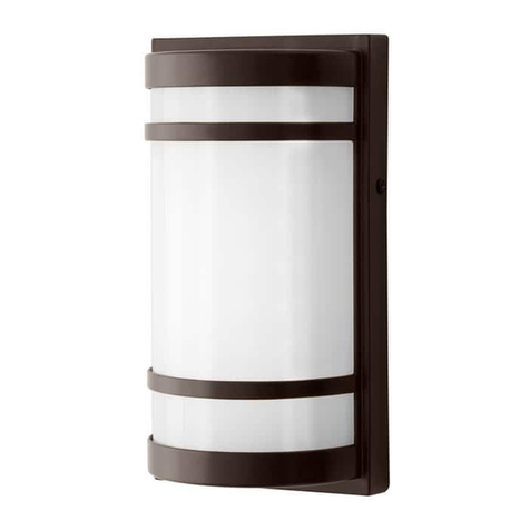
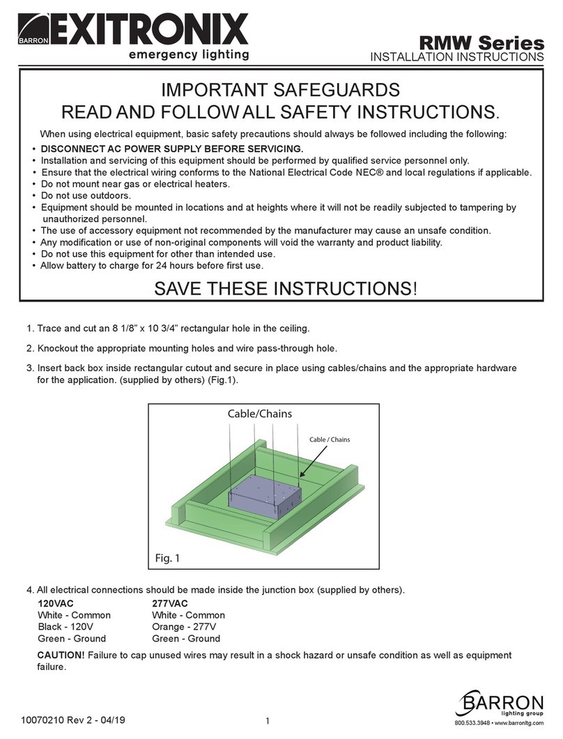
Exitronix RMW Series User manual

Exitronix

Exitronix RMW Series User manual

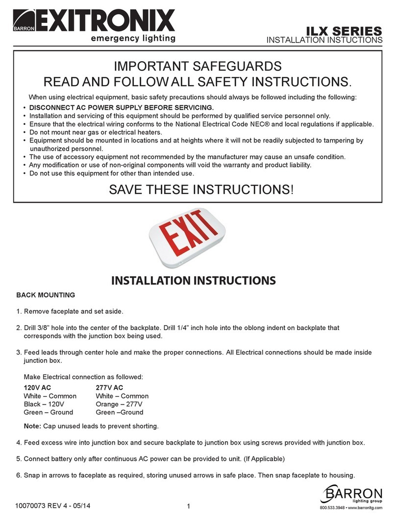
Exitronix ILX Series User manual

Exitronix

Exitronix ILX Series User manual

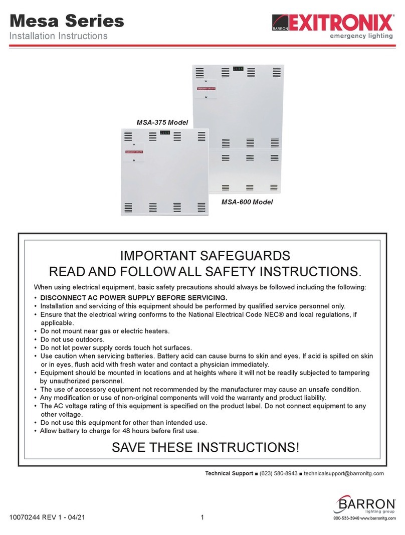
Exitronix Mesa Series User manual

Exitronix

Exitronix Mesa Series User manual

Popular Light Fixture manuals by other brands

Oase Lunaled 6s operating instructions

Oase

Oase Lunaled 6s operating instructions

brennenstuhl ALCINDA SERIES operating instructions

brennenstuhl

brennenstuhl ALCINDA SERIES operating instructions

Eurotops Versand 085010 manual

Eurotops Versand

Eurotops Versand 085010 manual

IKEA AKTIVERAD J1920 quick start guide

IKEA

IKEA AKTIVERAD J1920 quick start guide

Trilux Oktalite B.VEO TRACK installation instructions

Trilux

Trilux Oktalite B.VEO TRACK installation instructions

Philips iColor Accent Powercore installation instructions

Philips

Philips iColor Accent Powercore installation instructions

Cooper Lighting PM615ob Specification sheet

Cooper Lighting

Cooper Lighting PM615ob Specification sheet

Panduit PATMFM4.0 Operation manual

Panduit

Panduit PATMFM4.0 Operation manual

Lightolier Lytecaster 2026WH specification

Lightolier

Lightolier Lytecaster 2026WH specification

Saxby Lucca MW Mini Instruction leaflet

Saxby

Saxby Lucca MW Mini Instruction leaflet

ABB Stanilite Standard installation manual

ABB

ABB Stanilite Standard installation manual

Home Decorators Collection 29800 Use and care guide

Home Decorators Collection

Home Decorators Collection 29800 Use and care guide

Robe Beam 250XT user manual

Robe

Robe Beam 250XT user manual

Lightolier Lytespan 9476 specification

Lightolier

Lightolier Lytespan 9476 specification

Lightolier Lytespan 9021 specification

Lightolier

Lightolier Lytespan 9021 specification

ALPHA LITE E Series user manual

ALPHA LITE

ALPHA LITE E Series user manual

Westinghouse W-588 owner's manual

Westinghouse

Westinghouse W-588 owner's manual

Exido Wellness Lamp 237-001 Specifications

Exido

Exido Wellness Lamp 237-001 Specifications

manuals.online logo
manuals.online logoBrands
  • About & Mission
  • Contact us
  • Privacy Policy
  • Terms and Conditions

Copyright 2025 Manuals.Online. All Rights Reserved.