Panduit PATMFM4.0 User manual

PATMFM4.0
PD29735A01
Rev. 02
August, 2020
PAT4.0 FLUSH MOUNT FIXTURE
OPERATION MANUAL
© Panduit Corp. 2020
Translation of the
Original Instructions
This manual contains instructions for the following:
PATMFM4.0
WARNING
•TO REDUCE THE RISK OF INJURY, USER
MUST READ INSTRUCTION MANUAL
Email:
EU Website:
www.panduit.com/emea
EU Email:
emeatoolservicecenter
@panduit.com
www.panduit.com
Technical Support:
Tel: 1-800-777-3300
Panduit Europe • EMEA Service
Center
Almelo, Netherlands
Tel: +31 546 580 452 • Fax: +31 546 580
441

© Panduit Corp.
2020
OPERATION MANUAL
PATMFM4.0
ENGLISH
1
TABLE OF CONTENTS
TABLE OF CONTENTS..............................................................................................................................................1
1: INTRODUCTION..................................................................................................................................................3
2: SYSTEM SPECIFICATIONS....................................................................................................................................3
2A: PATMFM4.0 Table-Top Fixture ...........................................................................................................................3
2B: Fixture Tool Cage.................................................................................................................................................4
2C: EI Communication Cable .....................................................................................................................................5
2D: Tip Deflector........................................................................................................................................................6
2E: Tool Cavity Cover.................................................................................................................................................6
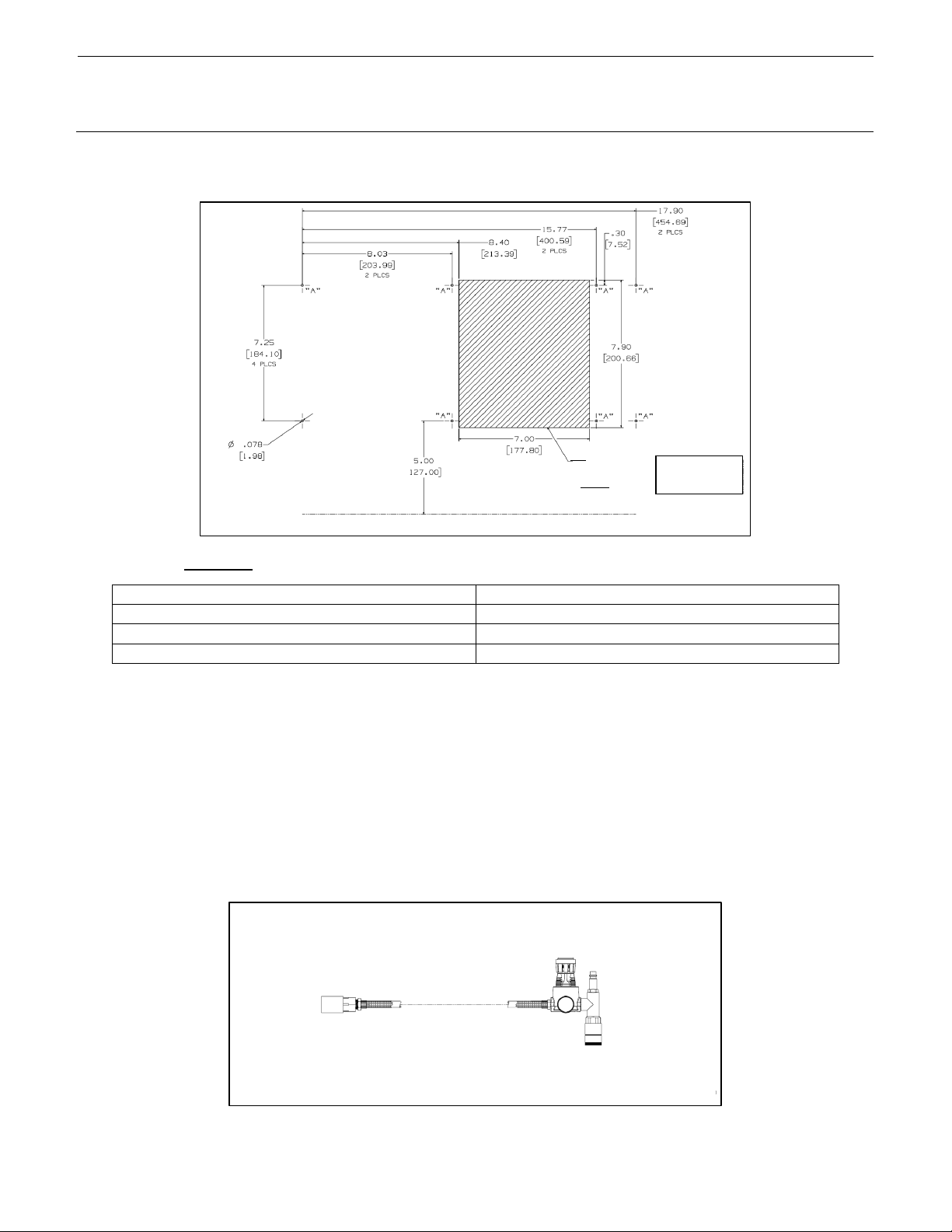
2F: Table-Top Template.............................................................................................................................................7
2G: Air Regulator.......................................................................................................................................................8
3: GENERAL POWER TOOL SAFETY WARNINGS ......................................................................................................9
3A: Work Area Safety....................................................................................................................................9
3B: Operational Safety Practices ................................................................................................................11
3C: Personal Safety .....................................................................................................................................11
3D: Power Tool Use and Care .....................................................................................................................12
3E: Service...................................................................................................................................................13
4: TECHNICAL SPECIFICATIONS............................................................................................................................. 13
4A: Air Supply ..........................................................................................................................................................13
4B: Environmental ...................................................................................................................................................14
5: INSTALLATION / SETUP ....................................................................................................................................14
5A: Take Inventory ..................................................................................................................................................14
5B. What’s Included.................................................................................................................................................14
5C. Modify Work Surface with Template................................................................................................................14
5D. PATMFM4.0 Fixture Assembly Installation(Ensure that the PAT4.0 system is off before installation). ............14
5E. Install PAT1M4.0/PAT1.5M4.0 Tool into Tool Cage ..........................................................................................15

© Panduit Corp.
2020
OPERATION MANUAL
PATMFM4.0
ENGLISH
2
5F. Install Tip Deflector onto The PAT1M4.0/PAT1.5M4.0 Tool..............................................................................17
5G. Mount Tool Cage Assembly onto Fixture Assembly ..........................................................................................17
5H. Electrical and Air Supply...................................................................................................................................21
5I. PHM Hose Installation........................................................................................................................................23
6: OPERATION......................................................................................................................................................25
6A: Start Up Checklist..............................................................................................................................................25
6B: Cable Tie Installation.........................................................................................................................................25
6C: Tip Deflector/Waste Receptacle........................................................................................................................29
7: MAINTENANCE ................................................................................................................................................ 30
7A: Preventative Maintenance................................................................................................................................30
8: TROUBLESHOOTING......................................................................................................................................... 31
8A: Error Message Troubleshooting........................................................................................................................31
9: BILL OF MATERIALS.......................................................................................................................................... 32
9A: WA29568E01 –Overlay Plate Assembly ...........................................................................................................32
9B: WA29569D01 –Tool Cage Assembly ................................................................................................................33
9C: WA29566C01 –Actuator Assembly...................................................................................................................33
9D: WA29567D01 –Electronics Enclosure Assembly ..............................................................................................34
9E: WA29653C01 –Air Regulator............................................................................................................................35
9F: Miscellaneous ....................................................................................................................................................35

© Panduit Corp.
2020
OPERATION MANUAL
PATMFM4.0
ENGLISH
3
1: INTRODUCTION
The PATMFM4.0 Table-Top Bench Mount Tool Fixture allows an operator to apply cable ties onto a wiring
harness with minimal strain. The fixture requires an existing PAT4.0 Fully Automatic Cable Tie Installation
System and can utilize both the PAT1M4.0 and PAT1.5M4.0 Handheld Tie Installation Tools. The PAT4.0
Hand Tool is mounted in the PATMFM4.0 fixture such that the work can be brought to the tool and actuated
simultaneously. Follow the step-by-step instructions below to install and operate the PATMFM4.0 Fixture.
NOTE: In the interest of higher quality and value, Panduit products are continually
being improved and updated.
Consequently, pictures may vary from the enclosed product.
2: SYSTEM SPECIFICATIONS
The Panduit Corporation PATMFM4.0 Table-Top Bench Mount Fixture consists of seven individual units:
The Table-Top Fixture, Fixture Tool Cage, EI Communication Cable, Tip Deflector, Tool Cavity Cover,
Table-Top Template and the PATMFM4.0 Air Regulator.
NOTE: Any substitution may cause serious damage to the system and/or injury to the operator.
2A: PATMFM4.0 Table-Top Fixture
The PATMFM 4.0 Table-Top Fixture is electrically and pneumatically controlled via an existing PAT4.0
System. A concealed electrical enclosure (Item E) manages these connections via Item(s) G,H and I.
Reference scales (Item(s) D) allow an operator to reference the distance relative to the PAT1M4.0 and
PAT1.5M4.0 jaw centers from either direction. An Actuation Paddle (Item C) lays flat in its storage position
until released via the spring-loaded latch (Item B). This paddle once released and in its operational position,
is actuated by the operator to preform work.
PATMFM4.0 Fixture General Overview:
A. Work Surface
B. Paddle Latch
C. Actuation Paddle
D. Reference Scale(s)
E. Electronics Enclosure
A
B
C
D
E
F
G
H
I

© Panduit Corp.
2020
OPERATION MANUAL
PATMFM4.0
ENGLISH
4
F. Electronics Enclosure Cover
G. Air-Regulator Input Fitting
H. EI Communication Port
I. Tool Cage air-line Output Quick-Connector
Table 2A: PATMFM4.0 Fixture Overall Specification
Dimension
Value
Length
19.32”(491mm)
Width
9.27” (235mm)
Height
6.53” (166mm)
Max Height Relative to Work Surface
1.79” (45mm)
2B: Fixture Tool Cage
The Fixture Tool Cage allows PAT1M4.0 and PAT1.5M4.0 Handheld Cable-Tie Installation Tools to be
mounted and installed into the PATMFM4.0 Table-Top Fixture. Installation of a Hand Tool is preceded by
removing the Rear Lower Tool Support (Item C) via the two thumbscrews (Item D). With the Rear Support
removed, a Hand Tool can be inserted and aligned relative to the Top and Bottom Front Tool Supports
(Item(s) A, B). Once a selected Tool is mounted into the Tool Cage and the Rear Support re-installed, the
Cage can be mounted onto the PATMFM4.0 Fixture, thus suspending the Tool such that only the top portion
of the Tool protrudes from the work surface. An airline (Item E) that exits the tool Cage is connected to the
PATMFM4.0 Fixture and delivers a controlled burst of air to the Actuation Trigger (Item G), engaging the
Tool Trigger (Item G) itself and beginning a cycle. Once complete, air is exhausted, the Actuation Trigger
retracts and the Tool is reset for a new cycle.
Fixture Tool Cage General Overview:
A
G
B
C
D
E
F
H

© Panduit Corp.
2020
OPERATION MANUAL
PATMFM4.0
ENGLISH
5
A. Front Upper Tool Support
B. Front Lower Tool Support
C. Rear Lower Tool Support
D. Retaining Thumbscrews
E. Tool Cage Airline
F. Tool Cage Retention Shoulder Screws
G. Actuation Trigger
H. Actuation Air Cylinder
Table 2B: Fixture Tool Cage Overall Specification
Dimension
Value
Length (Max-excluding airline)
4.63” (118mm)
Width (Max)
4.16” (106mm)
Height (Max)
6.28” (160mm)
2C: EI Communication Cable
The EI Communication Cable routes power and data between the PAT4.0 System and the PATMFM4.0
Fixture. This is a standard 25 Position D-Sub Male to Male connector cable that utilizes Philips head screws
on both connector ends for retention. The Cable delivers power to the PATMFM4.0 Fixture from the PAT4.0
System and relays cycle status and Actuation Paddle state back to the PAT4.0 System.
EI Communication Cable General Overview:

© Panduit Corp.
2020
OPERATION MANUAL
PATMFM4.0
ENGLISH
6
Table 2C: EI Communication Cable Overall Specification
Length
Width
Height
2m (6.56 ft)
2.17” (55mm)
0.65” (17mm)
2D: Tip Deflector
The Tip Deflector is similar to the Tip Collector originally provided with the PAT1M4.0 and PAT1.5M4.0
Handheld Tie Installation Tools. Instead of collecting the scrap produced, the Tip Deflector acts to divert
the waste under the work surface such that an appropriately located waste receptacle can be used under
said surface to collect scrap from multiple jobs/cycles without constant removal and clean up.
Tip Deflector General Overview:
Table 2D: Tip Deflector Overall Specification
Dimension
Value
Length
3.58” (91mm)
Width
2.09” (53mm)
Height
2.25” (57mm)
2E: Tool Cavity Cover
The Tool Cavity Cover is utilized when work is NOT preformed and a PAT1M4.0 or PAT1.5M4.0 Tool is
NOT installed within the Fixture Tool Cage (The Tool Cage can remain mounted onto the PATMFM4.0
Fixture). The Cavity Cover installs into the cavity, located on the top side of the PATMFM4.0 Fixture, in
order to restore the work surface area lost. This Cover aids in reducing the chance of materials falling
through this tool “cavity” and can be easily removed to resume work.

© Panduit Corp.
2020
OPERATION MANUAL
PATMFM4.0
ENGLISH
7
Tool Cavity Cover General Overview:
Table 2E: Tool Cavity Cover Overall Specification
Dimension
Value
Length
7.18” (182mm)
Width
2.46” (62mm)
Height
0.13” (3.3mm)
2F: Table-Top Template
The Table-Top Template is used prior to PATMFM4.0 Fixture installation in order to prepare a selected
work surface for the Fixture. A perimeter pattern of eight (8) total through holes and an aligned rectangular
pocket must be drilled and routed respectively in order to install the PATMFM4.0 Fixture successfully. A
proper work surface can be made from a variety of materials, either homogenous or engineered and the
PATMFM4.0 Fixture includes the necessary hardware for installation onto hardwood-based surfaces.
Reference the Minimum Work Surface Requirements table below for the minimum work surface dimensions
required to successfully install the PATMFM4.0 Fixture.

© Panduit Corp.
2020
OPERATION MANUAL
PATMFM4.0
ENGLISH
8
Table-Top Template General Overview:
Table 2F: Minimum Work Surface Specification
Dimension
Value
Length
22.0” (559mm)
Width
18.0” (457mm)
Depth
1.00” (25.4mm)
2G: Air Regulator
The PATMFM4.0 Air Regulator is designed to split and effectively “branch” the air regulator connection
already utilized by the PAT4.0 Fully Automatic Cable Tie Installation System. This branching air regulator
connects between the PAT4.0 System’s Air Regulator output and PAT4.0’s air input fitting to provide a
reduced operating pressure utilized by the PATMFM4.0 Fixture. The PATMFM4.0 Air Regulator is
adjustable and should be set to the recommended output specification (Table 4A) before connecting to and
operating the Fixture. Confirm this output pressure via the Air Regulator’s pressure gauge.
Air Regulator General Overview:
WORK SURFACE
DEPTH MUST BE
AT MIN. 1.00”
STEP 2:
REMOVE MAT’L
WITHIN SOLID
PERIMETER.
MIN. DISTANCE
FROM LEADING
EDGE OF WORK
SURFACE.
STEP 1:
DRILL x8 5/64”
THROUGH HOLES
INTO WORK
SURFACE.
(MARKED “A”)
TO PATMFM4.0
AIR INPUT FITTING
MIN: 40 PSI (2,8 bar)
MAX: DO NOT EXCEED 45 PSI (3,1 bar)
TO PDM4.0
AIR INPUT FITTING
TO PDM4.0 AIR
REGULATOR OUTPUT
MIN: 65 PSI (4,5 bar)
MAX: DO NOT EXCEED 85 PSI (5,8 bar)
MIN: 65 PSI (4,5 bar)
MAX: DO NOT EXCEED 85 PSI (5,8 bar)

© Panduit Corp.
2020
OPERATION MANUAL
PATMFM4.0
ENGLISH
9
3: GENERAL POWER TOOL SAFETY WARNINGS
The PAT4.0 Flush Table-Top Bench Mount System is pneumatically and electrically operated and
electronically controlled via an existing PAT Fully Automatic Cable Tie Installation System. Therefore,
certain safety practices must be followed.
WARNING
•Read all safety warning and all instructions. Failure to follow the
warnings and instructions may result in electric shock, fire and/or serious
injury.
•Save all warnings and instructions for future reference.
•The term “power tool” in the warnings refers to your main-operated (corded)
power tool or battery-operated (cordless) power tool.
Panduit Corp. recommends the fixture be used with all installed safety
features. Customer assumes all liability for injury that could result from
improper use of this fixture and responsibility for all necessary training to
ensure safe operation of this fixture.
•FOR INSTALLATION AND USE BY TRAINED PERSONNEL ONLY.
•IF ANY DAMAGE TO THE PRODUCT IS APPARENT OR SUSPECTED,
DO NOT USE THE PRODUCT. REFER PRODUCT TO QUALIFIED
SERVICE PERSONNEL.
•FCC WARNING: CHANGES OR MODIFICATIONS TO THE PRODUCT
COULD VOID THE USER’S AUTHORITY TO OPERATE THE PRODUCT.
3A: Work Area Safety
WARNING
DO NOT OPERATE POWER TOOLS IN EXPLOSIVE ATMOSPHERES, SUCH
AS IN THE PRESENCE OF FLAMMABLE LIQUIDS, GASES OR DUST.
Power tools create sparks which may ignite the dust or fumes.
Provide adequate ventilation around the product.

© Panduit Corp.
2020
OPERATION MANUAL
PATMFM4.0
ENGLISH
10
WARNING
KEEP WORK AREA CLEAN AND WELL LIT.
Cluttered or dark areas invite accidents.
Do not use in dusty environments.
KEEP CHILDREN AND BYSTANDERS AWAY WHILE OPERTING
A POWER TOOL.
Distractions can cause you to lose control.
WARNING
Power tool plugs must match the outlet. Never modify the plug in any way.
Do not use any adapter plugs with earthed (grounded) power tools.
Unmodified plugs and matching outlets will reduce risk of electric shock.
WARNING
ONLY OPERATE THE PATMFM4.0 SYSTEM IN A CLEAN, DRY,
INDOOR ENVIRONMENT.
DO NOT EXPOSE POWER TOOLS TO RAIN OR WET CONDITIONS.
Water entering a power tool will increase the risk of electric shock.
When operating a power tool outdoors, use an extension cord suitable for
outdoor use. Use of a cord suitable for outdoor use reduces the risk of electric
shock.
If operating a power tool in a damp location is unavoidable, use a residual
current device (RCD) protected supply. Use of an RCD reduces the risk of
electric shock.
NOTE: The term “residual current device (RCD)” may be replaced by the term “ground
fault circuit interrupter (GFCI)” or “earth leakage circuit breaker (ELCB)”.

© Panduit Corp.
2020
OPERATION MANUAL
PATMFM4.0
ENGLISH
11
KEEP AWAY FROM LIVE CIRCUITS:
•Operating personnel must use caution when opening covers.
•Replacement of components and internal adjustments must be made by
qualified maintenance personnel.
•Disconnect power cable when replacing components.
•Dangerous voltages may exist even with the power cable removed.
•To avoid injuries, always disconnect power and discharge circuits by
grounding before touching circuitry.
•Input connection to the product must remain accessible as a disconnect
device.
•DO NOT work on the product; connect or disconnect cables during periods
of lightning.
•Provide wiring per national and local electrical codes.
3B: Operational Safety Practices
1. DO NOT insert fingers in between the jaws of the tool.
2. DO NOT operate the tool with the rear jaw held open. Cable ties may be ejected from the tool at
high velocities.
3. DO NOT operate the tool near anyone's face.
4. DO NOT operate the tool without a wire bundle in the jaws.
5. DO NOT operate the tool with any object blocking the path of the cable tie around the jaws.
3C: Personal Safety
WARNING
Use personal protective equipment. Always wear eye protection. Protective
equipment such as dust mask, non-skid safety shoes, hard hat, or hearing
protection used for appropriate conditions will reduce personal injuries.
WARNING
Hearing protection is recommended to be worn during operation of tool.
1. STAY ALERT, watch what you are doing and use common sense when operating a power
tool. Do not use a power tool while you are tired or under the influence of drugs, alcohol
or medication.
A moment of inattention while operating power tools may result in serious personal injury.

© Panduit Corp.
2020
OPERATION MANUAL
PATMFM4.0
ENGLISH
12
2. Prevent unintentional starting. Ensure the actuation paddle is in the actuation-position
before connecting to a power source or turning on the PAT4.0 System.
Unlatching the paddle whilst the PAT4.0 system is powered can cause an unintended tie cycle to
occur.
3. Remove any adjusting key or wrench before turning the power tool on.
A wrench or a key left attached to a rotating part of the power tool may result in personal injury.
4. Dress properly. Do not wear loose clothing or jewelry. Keep your hair, clothing and
gloves away from moving parts.
Loose clothes, jewelry or long hair can be caught in moving parts.
5. If devices are provided for the connection of dust extraction and collection facilities,
ensure these are connected and properly used.
Use of dust collection can reduce dust-related hazards.
6. To prevent unintentional injury, DO NOT place the PATMFM4.0 where a ladder is required
for access.
3D: Power Tool Use and Care
1. Do not force the power tool. Use the correct power tool for your application.
The correct power tool will do the job better and safer at the rate for which it was designed.
2. Do not use the power tool if the switch does not turn it on and off.
Any power tool that cannot be controlled with the switch is dangerous and must be repaired.
3. Disconnect the plug from the power source and/or the battery pack from the power tool
before making any adjustments, changing accessories, or storing power tools.
Such preventive safety measures reduce the risk of starting the power tool accidentally.
4. Store idle power tools out of the reach of children and do not allow persons unfamiliar
with the power tool or these instructions to operate the power tool.
Power tools are dangerous in the hands of untrained users.
5. Maintain power tools. Check for misalignment or binding of moving parts, breakage of
parts and any other condition that may affect the power tool’s operation. If damaged, have
the power tool repaired before use.
Many accidents are caused by poorly maintained power tools.
6. Keep cutting tools sharp and clean.
Properly maintained cutting tools with sharp cutting edges are less likely to bind and are easier to
control.
7. Use the power tool, accessories and tool bits, etc. in accordance with these instructions,
considering the working conditions and the work to be performed.
Use of the power tool for operations different from those intended could result in a hazardous
situation.

© Panduit Corp.
2020
OPERATION MANUAL
PATMFM4.0
ENGLISH
13
3E: Service
•Have your Fixture serviced by a qualified repair person using only identical replacement
parts.
Contact Panduit Electrical Products Division Service at the following locations:
Panduit Electrical Products Division
(USA)
16530 W. 163rd Street
Lockport, IL 60441
888-506-5400, ext. 83255
Panduit EMEA Service Center (EUR)
EMEA Tool Service Center
Bedrijvenpark Twente 360
7602 KL Almelo
tel + 31 546 580 451
This will ensure that the safety of the fixture is maintained.
The information contained in this manual is based on our experience to date and is believed to be reliable. It
is intended as a guide for use by persons having technical skill at their own discretion and risk. We do not
guarantee favorable results or assume any liability in connection with its use. Dimensions contained herein
are for reference purposes only. For specific dimensional requirements consult the factory. This publication is
not to be taken as a license to operate under, or a recommendation to infringe any existing patents.
4: TECHNICAL SPECIFICATIONS
4A: Air Supply
ITEM
DESCRIPTION
PATMFM4.0 Recommended regulated air pressure to
fixture. (pressures other than recommended may
result in unsatisfactory operation):
MIN.: 40 PSI (2,8 bar)
MAX: DO NOT EXCEED 45 PSI (3,1 bar).
Max. recommended pressure drop: 5PSI (0.34bar)
PATMFM4.0 Filter/regulator requirements:
•40-micron maximum element rating
•5 PSI (0,3 bar) maximum pressure drop @
45 PSIG (3,1 bar) inlet pressure
•12 cfm (5,7 l/sec) flow minimum.
Lubrication for air supply:
Air-line lubricators are NOT to be used. Lubricators
will damage internal system components and seals.
PAT4.0 Recommended filter/regulator unit (supplied
by user) 3/8" NPT ports:
Recommended source:
Panduit Part Number PL283N1.

© Panduit Corp.
2020
OPERATION MANUAL
PATMFM4.0
ENGLISH
14
4B: Environmental
When storing and transporting an unused unit, please take care to use the original packaging.
Operational Temperature and Humidity
+10C(+50F) to +38C(+100F) Max 90% RH
Non-Condensing
Storage/ Transportation Temperature and Humidity
-40C(-40F) to +70C (+158F) Max 90% RH
Non-Condensing
5: INSTALLATION / SETUP
5A: Take Inventory
1. Remove components from the shipping box and refer to section 5B for an itemized component list.
5B. What’s Included
1. WA29569D01 - Tool Cage Assembly
2. WA29568E01 and WA29567D01 - PATMFM4.0 Fixture Assembly
3. WA29602C01 - Tip Deflector
4. WA29606D01 - Table-Top Template
5. CA29558B01 - EI Communication Cable
6. WA29653C01 - Air Regulator
7. WA29516B01 - Tool Cavity Cover
8. CA29740B01 - (x8) #6-1.0”Mounting Screws (For Wood)
5C. Modify Work Surface with Template
1. Lay the cut-out template down onto the desired work surface. A dashed line on the template denotes the
minimum distance relative to the leading edge, as required by the fixture. Once the template is aligned
appropriately, secure the sheet at each corner and ensure the template is flat against the work surface.
2. Using the template as a guide, drill a total of eight (8) 5/64”diameter through holes.
3. Using the template as a guide, cut inside the solid rectangular outline.
4. Once the above has been completed, remove the template and recycle.
5. This completes the process of preparing a work surface for the fixture to be installed.
(If the required work surface is to be metal, use the appropriate countersunk sheet metal fasteners and
hardware in the next step –not included).
5D. PATMFM4.0 Fixture Assembly Installation(Ensure that the PAT4.0 system is off before
installation).
1. Secure the Fixture Assembly to the work surface using the provided #6 Philips head screws around the
perimeter of the Overlay Plate. Pay attention to the sensor wiring located on the underside of the Fixture
Assembly. Be careful not to pinch the sensor harness between the Assembly and the work surface.

© Panduit Corp.
2020
OPERATION MANUAL
PATMFM4.0
ENGLISH
15
Installing PATMFM4.0 Fixture Assembly onto the work surface:
5E. Install PAT1M4.0/PAT1.5M4.0 Tool into Tool Cage
1. Back off the two thumbscrews located towards the back of the tool cage.
2. Once the thumbscrews are loosened, the Rear Lower Tool Support Block will disengage from the Tool Cage
Assembly.
3. Insert the PAT1M4.0 or PAT1.5M4.0 into the Tool Cage, ensuring that the Tool properly aligns within the
Front Upper and Lower Tool Supports. Proper installation can be verified by ensuring the Tool Cage
Actuator Trigger aligns well with the PAT1M4.0 or PAT1.5M4.0 finger trigger.
4. Reinstall the Rear Lower Tool Support Block and thumbscrews. Hand-tighten until the Tool is supported
within the Tool Cage and does not shift.
x8 #6x1.0”
WOOD SCREWS
USE APPROPRIATE SHEET
METAL FASTENERS AND
HARDWARE
IF MOUNTING TO METAL WORK
SURFACE.
(NOT PROVIDED)

© Panduit Corp.
2020
OPERATION MANUAL
PATMFM4.0
ENGLISH
16
PAT1M4.0/PAT1.5M4.0 Tool Installed into Tool Cage:
Tool Cage Cut-Away View Depicting Proper Tool Mounting:
1. REMOVE x2 REAR THUMBSCREWS
2. REMOVE REAR LOWER TOOL SUPPORT.
3. INSTALL PAT1M4.0/PAT1.5M4.0 TOOL INTO
UPPER AND LOWER FRONT TOOL SUPPORTS.
4. REINSTALL REAR LOWER SUPPORT AND
THUMBSCREWS.
5. HAND TIGHTEN UNTIL FIRM.
CUT-AWAY VIEW DEPICTING
PROPER TOOL SEATING AND ALIGNMENT
UPPER FRONT
TOOL SUPPORT
FRONT LOWER
TOOL SUPPORT
REAR LOWER
TOOL SUPPORT
TOOL TRIGGER

© Panduit Corp.
2020
OPERATION MANUAL
PATMFM4.0
ENGLISH
17
5F. Install Tip Deflector onto The PAT1M4.0/PAT1.5M4.0 Tool
1. Install the Tip Deflector onto the PAT1M4.0/PAT1.5M4.0 Tool. The installation process mirrors the
Tool’s originally provided Tip Collector.
Tip Deflector Installation:
5G. Mount Tool Cage Assembly onto Fixture Assembly
1. The Tool Cage features 4 shoulder bolts that align and are retained by 4 corresponding “tracks” located
on the underside of the Fixture. Once aligned with the track openings, simply guide the Tool Cage
along the tracks until seated. A properly engaged Tool Cage will not shift or release from the Fixture
Assembly unless guided back and out of the tracks.
2. For aiding installation, releasing the Actuation Paddle (with the PAT4.0 switched off) will reveal a single
track located underneath the Paddle. This can assist in visually aligning and ensuring proper
engagement.
3. Route the Tool Cage airline to the Fixture Assembly’s air output quick connector. This is a brass quick
connector featuring an orange quick-release ring. To insert, simply press the airline into the brass
feature until the airline bottoms out.
(To disengage the airline, simply press the orange ring into the connector whilst pulling the airline out
and away).
ENGAGE TIP DIVERTER ONTO
TOOL AND SLIDE BACK (TOWARDS
HANDLE) TO LOCK.
PROPERLY MOUNTED
TIP DIVERTER ON
PAT1M4.0 TOOL.

© Panduit Corp.
2020
OPERATION MANUAL
PATMFM4.0
ENGLISH
18
Mounting the Tool Cage (and Tool) from the underside of the Fixture:
Tool Cage against Guiding Edge(s):
“TRACKS”
GUIDING EDGE
THE TOOL CAGE IS
INSTALLED FROM THE
UNDERSIDE OF THE
PATMFM4.0 FIXTURE.
USE THE GUIDING EDGES
TO ALIGN AND ENGAGE THE
TOOL CAGE “TRACKS”.
FOLLOW ALONG THE TRACK
PATH UNTIL THE CAGE IS
PROPERLY RETAINED BY THE
FIXTURE.
THE TOOL CAGE SHOULDER SCREW(S)
ALIGNED AGAINST THE GUIDING EDGE(S).

© Panduit Corp.
2020
OPERATION MANUAL
PATMFM4.0
ENGLISH
19
Tool Cage aligned with Start of Fixture Track(s):
Tool Cage Properly Guided and Retained Within Fixture Tracks:
REAR TRACK EDGE(S).
TOOL CAGE SHOULDER SCREWS ALIGNED WITH START OF “TRACKS”.
FOLLOW TRACK PATTERN
UNTIL REAR TRACK EDGES ARE REACHED.
TOOL CAGE SHOULDER SCREWS PROPERLY
SEATED AT END OF FIXTURE TRACKS.
REPEAT THIS PROCESS IN THE REVERSE ORDER
TO REMOVE THE TOOL CAGE SUB-ASSEMBLY.
Other manuals for PATMFM4.0
1
Table of contents
Popular Light Fixture manuals by other brands

Sammode
Sammode RIMBAUD Mounting instruction

Avlite
Avlite AV-OL-ILAB-12-R-D Installation & service manual

AWELL
AWELL LWRE2012 instructions

Triarch
Triarch 25983 installation instructions

Larson Electronics
Larson Electronics EPL-HB-5K-LED instruction manual

American DJ
American DJ Accu Scan 250 User instructions