Expand-it ALT-03 User manual
ALT-03
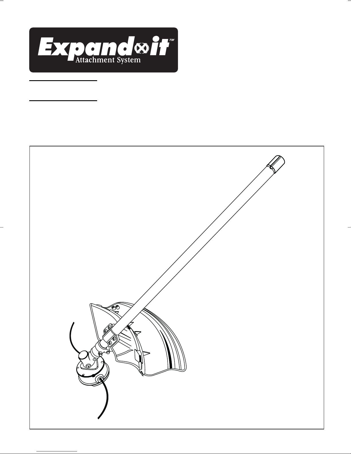
LINE TRIMMER ATTACHMENT
OPERATOR’S MANUAL
ALT-03_Eng.qxp 5/19/2004 8:58 AM Page A1
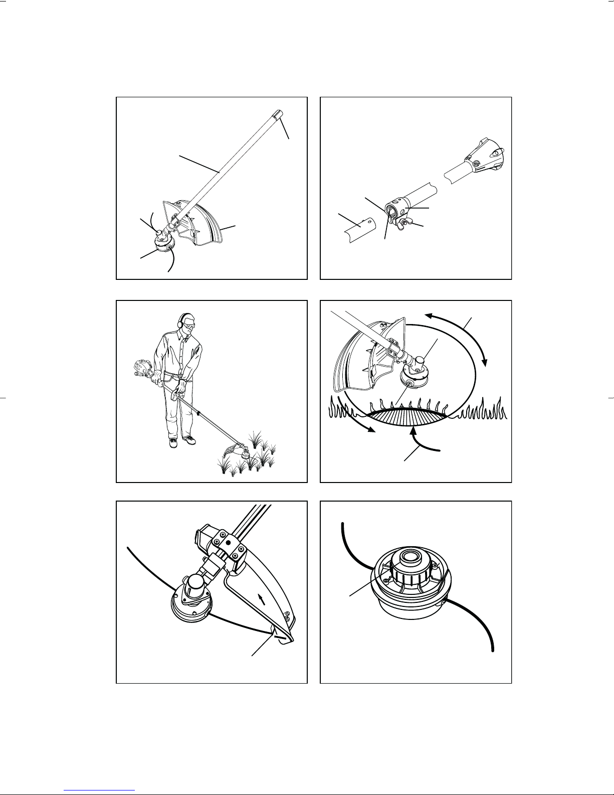
Fig. 1
Fig. 3Fig. 2
Fig. 5Fig. 4
6
7
8
1
9
12
13
10
11
12
3
4
5
ALT-03_Eng.qxp 5/19/2004 8:58 AM Page A2
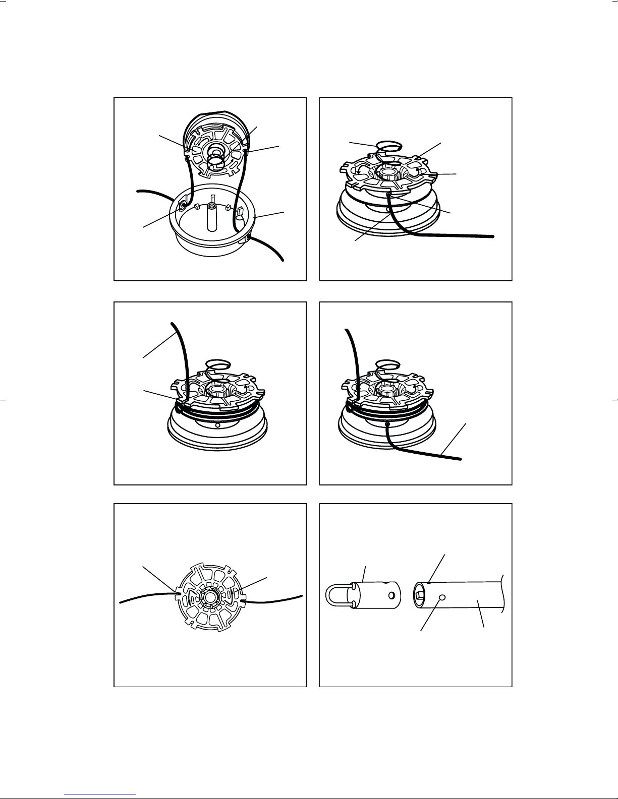
Fig. 9Fig. 8
Fig. 10
Fig. 7Fig. 6
Fig. 11
17
14
15
16
18
15 16
21
20
19
19
17
22
17
21
25
1
23
24
ALT-03_Eng.qxp 5/19/2004 8:58 AM Page A3

Important!
It is essential that you read the instructions in this
manual before mounting and operating this machine.
Subject to technical modifications
ALT-03_Eng.qxp 5/19/2004 8:58 AM Page A4

SAFETY RULES
WARNING
Read and understand all instructions. Failure
to follow all instructions listed below, may result in
electric shock, fire and/or serious personal injury.
SAVE THESE INSTRUCTIONS.
GENERAL SAFETY RULES
■For safe operation, read and understand all
instructions before using the straight shaft trimmer
attachment. Follow all safety instructions. Failure to
follow all safety instructions listed below, can result in
serious personal injury.
■Do not allow children or untrained individuals to use
this unit.
■Wear safety glasses or goggles that are marked to
comply with ANSI Z87.1 standards and hearing
protection when operating this unit.
■Wear heavy long pants, boots, and gloves. Do not
wear loose fitting clothing, short pants, jewelry of any
kind, or go barefoot.
■Secure long hair so it is above shoulder level to
prevent entanglement in any moving parts.
■Keep all bystanders, children, and pets at least
15 m away.
■Do not operate this unit when you are tired, ill,
or under the influence of alcohol, drugs, or medication.
■Do not operate in poor lighting.
■Keep firm footing and balance. Do not overreach.
Overreaching can result in loss of balance or
exposure to hot surfaces.
■Keep all parts of your body away from any moving part.
■Do not touch areas around the muffler or cylinder of
the power head, these parts get hot from operation.
Failure to do so could result in possible serious
personal injury.
■Always stop the engine and remove the spark plug
wire before making any adjustments or repairs except
for carburetor adjustments.
■Inspect unit before each use for loose fasteners,
damaged or missing parts. Correct before using the
straight shaft trimmer attachment. Failure to do so can
cause serious injury.
■Check for damaged parts. Before further use of the
appliance, any part that is damaged should be
carefully checked to determine that it will operate
properly and perform its intended function.
Check for alignment of moving parts, binding of
moving parts, breakage of parts, mounting, and any
other conditions that may affect its operation. A guard
or other part that is damaged should be properly
repaired or replaced by an authorized service center.
■Use only original manufacturer’s replacement parts.
Failure to do so, may cause poor performance,
possible injury, and will void your warranty.
■Do not, under any circumstance, use any attachment
or accessory on this product which was not provided
with the product or identified as appropriate for use
with this product in the Operator’s Manual.
SPECIFIC SAFETY RULES FOR TRIMMER USE
■Replace string head if cracked, chipped, or damaged
in any way. Be sure the string head is properly
installed and securely fastened. Failure to do so can
cause serious injury.
■Make sure all deflectors and handles are properly and
securely attached.
■Use only the manufacturer's replacement string in the
cutting head. Do not use any other cutting attachment
unless specifically noted in operator’s manual.
■Never operate string trimmer without the grass
deflector in place and in good condition.
■Maintain a firm grip on both handles while trimming.
Keep string head below waist level. Never cut with the
string head located over 76 cm or more above
the ground
1
English
ALT-03_Eng.qxp 5/19/2004 8:58 AM Page A5

DESCRIPTION
1. Attachment Shaft
2. End Cap
3. Gear Head
4. String Head
5. Guard
6. Knob
7. Coupler
8. Guide Recess
9. Positioning Hole
10. Best Cutting Area
11. Dangerous Cutting Area
12. Cut-off Blade
13. Spool Retainer
14. String Head
15. Spring
16. Spool
17. Slots
18. Eyelets
19. First String
20. Anchor Hole
21. Arrows On Spool
22. Second String
23. Hanger Cap
24. Button
25. Secondary Hole
ASSEMBLY
JOINING THE POWER HEAD TO THE
STRAIGHT SHAFT TRIMMER ATTACHMENT
(Fig. 1)
WARNING
Never attach or adjust any attachment while
power head is running. Failure to stop the engine
may cause serious personal injury
The straight shaft trimmer attachment connects to the
power head by means of a coupler device.
■Loosen the knob (6) on the coupler (7) of the power
head shaft and remove the end cap (2) from the
attachment shaft (1).
2
English
SYMBOLS
Important: Some of the following symbols may be used on your tool. Please study them and learn their meaning.
Proper interpretation of these symbols will allow you to operate the tool better and more safely.
SYMBOLS NAME EXPLANATION
Safety Alert Symbol Indicates danger, warning or caution. it means attention!!!
Your safety is involved.
Read Your Operator's Manual Your manual contains special messages to bring attention to
potential safety concerns as well as operating and servicing
information. Please read all the information carefully to ensure
satification and safe use.
Wear eye and hearing protection Wear eye, and hearing protection when operating this
equipment.
Keep bystanders away Keep all bystanders at least 15m (50 ft) away.
Ricochet Danger of Ricochet.
Do not use toothed blade This unit is not intended for use with a toothed saw type blade.
ALT-03_Eng.qxp 5/19/2004 8:58 AM Page A6

ASSEMBLY
■Push in the button located on the straight shaft
trimmer attachment shaft. Align the button with the
guide recess (8) on the power head coupler and slide
the two shafts together. Rotate the straight shaft
trimmer attachment shaft (1) until the button locks into
the positioning hole (9).
NOTE: If the button does not release completely in
the positioning hole, the shafts are not locked into
place. Slightly rotate from side to side until the button
is locked into place
■Tighten the knob securely
WARNING
Be certain the knob is fully tightened before
operating equipment; check it periodically for
tightness during use to avoid serious injury or
product damage
REMOVING THE ATTACHMENT FROM THE
POWER HEAD
For removing or changing the attachment:
■Loosen the knob.
■Push in the button and twist the shafts to remove and
separate ends.
OPERATION
OPERATING THE TRIMMER (Fig. 2)
Hold the trimmer with the right hand on the rear handle
and the left hand on the front handle. Keep a firm grip
with both hands while in operation. Trimmer should be
held at a comfortable position with the rear handle about
hip height.
Always operate trimmer at full throttle. Cut tall grass from
the top down. This will prevent grass from wrapping
around the shaft and string head which may cause
damage from overheating. If grass becomes wrapped
around the string head, stop the engine, disconnect the
spark plug wire, and remove the grass. Prolonged cutting
at partial throttle will result in oil dripping from the muffler.
ADVANCING THE STRING
String advance is controlled by tapping string head on
grass while running engine at full throttle.
■Run engine at full throttle.
■Tap string head on ground to advance string.
String advances each time the head is tapped.
■Several taps may be required until string strikes the
cut off blade.
■Resume trimming.
NOTE: If the string is worn too short you may not be
able to advance the string by tapping it on the ground.
If so, stop the engine, disconnect the spark plug wire,
and manually advance the string.
ADVANCING THE STRING MANUALLY
Push the spool retainer down while pulling on string(s) to
manually advance the string.
CUTTING TIPS (Fig. 3)
■Keep the trimmer tilted toward the area being cut;
this is the best cutting area (10).
■Do not cut in dangerous cutting area (11).
■Use the tip of string to do the cutting; do not force
string head into uncut grass.
■Wire and picket fences cause extra string wear, even
breakage. Stone and brick walls, curbs, and wood
may wear string rapidly.
■Avoid trees and shrubs. Tree bark, wood moldings,
siding, and fence posts can easily be damaged by
the string.
OPERATION
GRASS DEFLECTOR LINE TRIMMING CUT-OFF
BLADE (Fig. 4)
This trimmer is equipped with a line trimming cut-off
blade on the grass deflector. For best cutting, advance
string until it is trimmed to length by the cut-off blade (12).
Advance string whenever you hear the engine running
faster than normal. This will maintain best performance
and keep string long enough to advance properly.
WARNING
Do not, under any circumstance, use any
attachment or accessory on this product which
was not provided with the product, or identified
as appropriate for use with this product in the
Operator’s Manual.
MAINTENANCE
WARNING
Use only original manufacturer's replacement
parts, accessories and attachments. Failure to do
so may cause poor performance, possible injury
and may void your warranty.
3
English
ALT-03_Eng.qxp 5/19/2004 8:58 AM Page A7

MAINTENANCE
You may make adjustments and repairs described in the
maintenance section. For other repairs, have the unit
serviced by an authorized servicing dealer.
SPOOL REPLACEMENT
NEW PREWOUND SPOOL (Fig. 5 & 6)
Use only 2.4 mm diameter monofilament string.
Use the manufacturer's replacement parts for best
performance.
■Stop the engine, hold the string head and unscrew
the spool retainer (13). Turn clockwise.
■Remove the empty spool from the string head (14).
Use the spring (15) from the empty spool if one is not
provided with the new spool and string.
■To install the new spool (16), make sure the two
strings are captured in the slots (17) opposite each
other on the new spool. Make sure the ends of each
string is extended approximately 6 in. (152 mm)
beyond each slot.
■Thread the strings into the eyelets (18) in the string
head. Carefully push the spool into the string head
(gently pull the strings to the outside if necessary).
When the spool is positioned in the string head, grasp
the strings and pull sharply to release them from the
slots in the spool.
■Push down and turn the spool counterclockwise until
it no longer turns. Hold the spool down and rotate
clockwise a small amount. Release the spool.
The spool should be locked down in the string head. If
not, hold down and rotate until locked.
■Make sure the string head and the spool retainer are
installed on the shaft by turning the retainer
counterclockwise to tighten.
■Pull the strings again to rotate the spool into cutting
position. Push the spool retainer down while pulling
on string(s) to manually advance the string and to
check for proper assembly of the string head.
STRING REPLACEMENT (Fig. 8 - 11)
■Stop the engine, disconnect the spark plug wire.
Hold the string head and unscrew the spool retainer.
Turn clockwise.
■Remove the spool from the string head.
NOTE: Keep the spring attached to the spool.
Remove any old string remaining on the spool.
■Cut two pieces of string, each being approximately
2.7 m long.
■Insert the first string (19) into the anchor hole (20)
in the upper part of the spool. Wind the first string
around the upper part of the spool counterclockwise,
as shown by the arrows on the spool (21).
Place string in the slot on upper spool flange, leaving
about 152 mm extended beyond the slot. Do not
overfill. After winding the string, there should be at
least 6 mm between the wound string and the outside
edge of the spool.
■Repeat above step with second string (22), using the
bottom part of spool. Do not overfill.
■Replace the spool and the spool retainer. Refer to
"Spool Replacement" earlier in this manual.
STORING THE STRAIGHT SHAFT TRIMMER
ATTACHMENT
Store the straight shaft trimmer attachment in a well
ventilated place that is inaccessible to children.
Keep away from corrosive agents such as garden
chemicals and deicing salts.
To remove the straight shaft trimmer attachment from the
power head for storage:
■Loosen the knob on the coupler device.
■Push the button in, then twist the shafts to remove
and separate the power head from the
attachment.
MAINTENANCE
ATTACHING THE STORAGE HANGER (Fig. 11)
There are two ways to hang your attachment for storage.
■To use the hanger cap (23), push in the button (24)
and place the hanger cap over end of the straight
shaft trimmer attachment shaft. Slightly rotate the cap
from side to side until the button locks into place.
■The secondary hole (25) in the straight shaft trimmer
attachment shaft can be used for hanging purposes
as well.
4
English
ALT-03_Eng.qxp 5/19/2004 8:58 AM Page A8

RYOBI TECHNOLOGIESAUSTRALIA PTY. LTD.
GUARANTEE
RYOBI TECHNOLOGIESAUSTRALIA PTY. LTD.
A.B.N. 98002 277 509
RYOBI NEW ZEALAND PTY. LTD.
AUCKLAND: 27 Clemow Drive, Mt Wellington, N.Z.
Contact during normalbusiness hours.
Subject to the guarantee condition below, thisRyobitool
(hereinafter called “the product”) isguaranteed byRyobi
(hereinafter called “the Company”) to be free from
defectsin material or workmanship for aperiod of 24
monthsfrom the date of originalpurchase covering
both partsand labour. Under the termsof this
guarantee, the repair or replacement of any part shall
be the opinion of the Company or itsauthorised agent.
Should service become necessary during the warranty
period, the owner should contact the RYOBI HELPLINE
1300 361 505 or contact the retailer from whom the
product was purchased.
In order to obtain guarantee service, the owner must
present the salesdocket and Guarantee Certificate
to confirm date of purchase. Thisproduct issold bythe
dealer or agent as principaland the dealer has no
authority from the Company to give any additional
guarantee on the Companyí sbehalf except as herein
containedorhereinreferredto.
Guarantee Conditions
Thisguarantee only appliesprovided that the Product
has been used in accordance with the manufacturer’s
recommendationsunder normaluseand reasonable
care (in the opinion of the Company) and such
guarantee doesnot cover damage, malfunction or
failure resulting from misuse, neglect, abuse, or used
for apurpose for which it was not designed or isnot
suited and no repairs,alterationsor modifications
have been attempted by other thananAuthorised
Service Agent. Thisguarantee will not apply if the tool is
damaged byaccident or if repairsarise from normal
wearand tear.
The Company acceptsno additionalliability pursuant to
thisguarantee for the costsof travelling or
transportation of the Product or partsto and from the
service dealer or agent - such costsare not included in
thisguarantee.
Certain legislation, including the Trade PracticesAct,
1974 (as amended) and other state and territoriallaws
give rightsto the buyer and imposeliability on the seller in
certain circumstances. Nothing herein shall have the effect
of excluding, restricting or modifying any condition,
guarantee, right or liability imposed, to the extent only
thatsuch exclusion, restriction or modification
would render any term herein void.
BRISBANE : All enquiriesTel : 1300 361 505
TOWNSVILLE: All enquiriesTel : 1 300 361 505
MELBOURNE:
HOBART: All enquiriesTel : 1 300 361 505
ADELAIDE: All enquiriesTel : 1 300 361 505
PERTH:
Address Of Dealer
Present ThisForm With YourPurchase Docket When Guarantee Service IsRequired.
Tel: - Fax: 1800 807 993- www.ryobi.com.au
Tel: (09) 5730230-FreeCall: 0800 279 624 - Fax: (09) 5730231 - www.ryobi.co.nz
For your record and to assistinestablishing date of purchase (necessary for in-guarantee service)
please keep yourpurchase docket and thisform completed with the following particulars.
ThisGuarantee Form Should Be Retained By The Customer At All Times
Date Model No SerialNo
SYDNEY: Building B, Rosehill Industrial Estate, 3-5 Shirley Street, Rosehill N.S.W. 2142
Contact during normal business hours.
1300 361 505
All enquiriesTel : 1300 361 505 33-35 Sorbonne Cres. Canning Vale, W.A. 6155
Tel : (08) 9455 7775
ALT-03_Eng.qxp 5/19/2004 8:58 AM Page A9
Table of contents
Popular Lawn And Garden Equipment manuals by other brands


Blumfeldt
Blumfeldt Highgrow Advanced manual

FarmTek
FarmTek Growers Supply GrowSpan Estate Elite 104711 instructions

ENCLO
ENCLO Bedford EC18003 Assembly instructions

Orbit
Orbit WaterMaster series Installation and operating instructions

Hard Head
Hard Head 021088 operating instructions

AL-KO
AL-KO 548 916 operating instructions