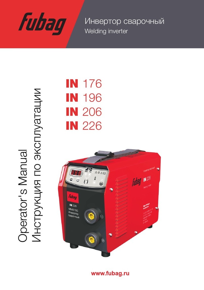
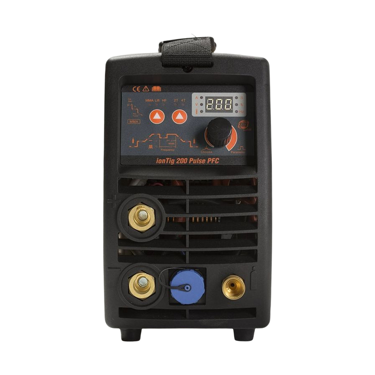
ExpressWeld Inverter 161 ARC161 User manual

Inverter 161
Rev. 2009/02
MMA WELDING MACHINE
OPERATION MANUAL
2 YEARS WARRANTY
MODEL : ARC161

EU - DECLARATION of CONFORMITY
EU - KONFORMITÄTSERKLÄRUNG
Déclaration de Conformité de l'EU
KAYNAK TEKNİĞİ SANAYİ ve TİCARET A.Ş.
Firm / Firma / Société
declares that the welding machine
erklärt, daß die Bauart der Maschine
déclare que le poste de soudage
®
EXPRESSWELD Inverter 161
conforms to the following directives
den folgenden Bestimmungen entspricht
est conformé aux directives suivantes
2004/108/EC, 2006/95/EC
and has been designed in compliance with the following standards
und in Überienstimmung mit den nachstehenden normen hergestellt wurde
et qu'il a été conçu en conformité avec les normes
EN 60974-1, EN 60974-10
Technical Services Manager / Directeur des Services Techniques
Kaynak Teknigi Sanayi ve Ticaret A.S.
TOSB - Taysad Organize Sanayi Bolgesi, 2. Cadde, No: 5, Sekerpinar, 41480 Gebze, Kocaeli - TURKEY
Ahmet SEVÜK
29.07.2008Date / Datum / Date :

February 2009
Safety in Welding
General Specifications
Installation and Operator Instructions
Preparation for Operation
Supplied Accessories
Maintenance & Troubleshooting
Electromagnetic Compatibility
Transport and Storage Conditions
Spare Parts
Electrical Connection Diagram
Technical Service and Other Contact Addresses
3 - 4
5
6
7 - 9
9
10
11 - 12
12
13 - 16
17
18
Table of Contents

3
Safety in Welding - 1
Only qualified personnel should use this machine. Be sure that all installation, operation,
maintenance and repair procedures are performed only by qualified person. Before operating the
machine read and understand the operation manual. Failure to observe instructions stated in this
manual may cause serious personal injury, death and damage the machine. Please read the
cautions stated with above symbols. Kaynak Teknigi Sanayi ve Ticaret A.S. is not responsible for
damages caused by improper installation, improper storage or abnormal operation.
WARNING: This symbol indicates that instructions must be followed to avoid serious
personal injury, loss of life or damage to this equipment. Protect yourself and others.
READ and UNDERSTAND INSTRUCTIONS: Read and understand this manual
before operating this equipment. Failure to follow the instructions in this manual may
cause serious personal injury, loss of life, or damage to this equipment.
ELECTRIC SHOCK MAY KILL: Welding machine produces high voltage that may be
harmful for human health. Do not touch the electrode, ground connection or electrically hot
parts while machine is operating. Isolate yourself against electrode, ground connection or
work piece. Since the risk of electrical shock exists, do not touch the metal ends of the plug
after it has been removed from the power.
FUMES and GASES MAY BE DANGEROUS: Welding operation produce fumes and gases
hazardous to health. To protect the users from this danger, there should be enough
ventilation or fumes and gases should be thrown away from the breathing zone.
WELDING ARC MAY BURN: Proper mask, filter and protective glass should be used to
protect your eyes from sparks and the rays of the arc when welding or observing. Skin
should be protected with flame-proof clothing. Protect nearby personnel with suitable, non-
flammable screening and warn them not to watch the welding arc or expose themselves to
the arc rays.
WELDING SPARKS MAY CAUSE FIRE or EXPLOSION : Keep the flammable materials
away from the welding area and put the fire extinguisher on an easily accessible place.
Remember that welding sparks and hot materials from welding can easily go through small
cracks and the most tight openings to adjacent areas. Do not weld on any jerrycan, barrel,
tank or material if you are not sure that precautions were taken to avoid flammable and
poisonous gasses totally from the environment. Never operate this equipment when
flammable gases, vapors or liquid combustibles are present.
This machine has been designed to make manual metal arc welding
and it can not be used for any other purposes.

ELECTRICALLY POWERED EQUIPMENT: Turn off input power using the switch at the fuse
box before working on the equipment. Electrical connections should be performed
adequate to the obligated rules.
GROUNDING: For your safety and trouble-free operation, electrical supply cables should
be connected to a proper grounded receptacle.
ELECTRICALLY POWERED EQUIPMENT: Check the conditions of electrode cables,
supply cables and the cables connected to the machine regularly. If you face an improper
condition, replace the defective parts with the new ones immediately. In order to prevent the
risk of arc explosion and fire, do not leave the electrode holder directly on the welding table
or on a surface that is contacting with the work clamp.
ELECTRIC and MAGNETIC FIELDS MAY BE DANGEROUS TO HUMAN HEALTH:
Electric that flows through conducters, produces electromagnetic field. This
electromagnetic field can be effective on devices like pacemakers. Users who have a
pacemaker must refer to a physiotherapist before operating the machine.
GAS CYLINDER MAY EXPLODE: Only use the compressed gas cylinders that contain
protective gas which is adequate for welding processes. Be sure that adequate regulators
for the gas and cylinder are correctly mounted on the cylinder. Always keep cylinders in an
upright position and securely chained to a fixed support. Do not change the places of the
cylinders before closing the protective covers. Avoid contact between electrodes, electrode
holders, work clamps and electrical parts with the gas cylinder. Stockpile the cylinders at a
distance from the areas that is called heat and spark producing.
COMPLIANCE WITH "CE" NORMS: The machine is produced in compliance with
European Acting Orders.
WELDED MATERIAL MAY BURN: Welding generates a large amount of heat. Hot surfaces
and materials can cause serious burns. Gloves should be worn while touching and carrying
this type of materials.
SAFETY MARK: This machine is suitable for supplying power for welding operations carried
out in an environment with increased hazard of electric shock.
4
Safety in Welding - 2

General Specifications
EXPRESSWELD Inverter 161, is an inverter welder which is produced with the latest inverter
technology.
Power source unit with inverter, is a technology that is introduced to the market in 1980.
50Hz/60Hz frequency is converted to 20 KHz or above, which means high frequency, by MOSFET
and then voltage is decreased and alternating current (AC) is converted to direct current (DC), a
powerful DC source current is created by using PWM technique in inverter technology, the size and
weight of the welding machine is decreased and the efficiency is increased by 30% with inverter
technology. The most important specifications of the welding machines that is produced with
inverter technology are providing stabile arc, safety, lightness and energy saving. The
improvement of welding machines with inverter is called a revolution in welding area by experts.
1 - High quality welding with proper DC current,
2 - Stabile welding arc,
3 - Easy controlling of molten welding puddle,
4 - Easy electrode ignition with high open circuit voltage,
5 - Application area width,
6 - Lightness,
7 - Easy installation and operating,
8 - 2 years service warranty after purchasing time.
The advantages of EXPRESSWELD Inverter 161:
Input
Input Voltage
220 V ± % 15
~ 1 Ph
Input Power
5.4 kVA (35% duty cycle)
4.7 kVA (60% duty cycle)
Frequency
50/60 Hertz (Hz)
Welding Current - Output Rating
Duty Cycle
(10 minutes period)
35%
60%
Output Current
(Amp.)
155 A
125 A
Output Voltage
(Volt)
26 V (DC)
25 V (DC)
Output Range
Welding Current Range
30 - 160 A
Maximum Open Circuit Voltage
60 V (DC)
Physical Properties
Height
260 mm
Width
135 mm
Length
375 mm
Weight
6 kg
Operating Temperature : Between - 10°C and + 40°C
Fuse Size and Type : 25 Amp. (delayed)
Power Factor (cos ) : 0.74
5

Installation and Operator Instructions
Read this entire section before installation or operation of the machine.
Location and Environment:
However, it is important that simple preventative measures are followed to assure long life and
reliable operation.
1 - Do not put or operate the machine on a surface that is inclined above 15°.
2 - The machine must be operated in an environment with fresh air flow and there musn't be any
factor that blocks or stops the ventilation or fresh air flow. The machine shouldn't be covered
with paper or similar things while operating.
3 - Dust and dirt may get into the machine. This condition should be minimized. Do not work in
environments that contain dense dust, grinding dust, corrosive gases and in atmospheres with
water, paint or oil particles.
4 - This machine is IP21S protection class. Keep it dry when possible and do not place it on wet
ground or in puddles.
5 - This machine is designed for indoor use. Never operate the welding machine under sunlight
and when there is a possibility of water splattering.
6 - Put the machine away from radio controlled devices. Normal operation may adversely affect
the operation of this type of devices, which may result in injury or equipment damage. Read the
electromagnetic accordance section in this manual.
7 - Do not operate this machine in ambient temperatures of less than -10°C and over +40°C and
80% humidity.
8 - If people who are unqualified about electrical equipments, opens the work cover and interfere
with the machine, they may face life threatining conditions. People who behave otherwise is
considered to accept the negative results.
9 - This welding machine is designed for light welding processes performed by using 2.50
and 3.20 mm diameter rutile and basic type stick electrodes.
Duty Cycle and Overheating:
The efficiency of the machine is the percentage of the rating of the welder performing welding
process without overheating and stopping for 10 minutes with the welding current given.
Machine is protected from overheating by its thermal protection. When this protection is enabled
the warning light on the front panel illuminates. When you return to the safe operating temperature
the light turns off and you may continue welding.
6

Preparation for Operation - 1
Input Cable Connection:
Check the input voltage, phases and frequency before operating the machine. Usable input
voltage values are indicated in the manual's technical specifications section and the plate on the
machine. Be sure that the grounding of the cables which connects the machine to the input
electricity are appropriate. Be sure that enough current is provided for the machine's normal
operation. Recommended fuse type and size is 25 Amps (delayed).
1 - This machine is designed to operate with 220-230 V, 1 Ph, AC 50-60 Hz supply voltage.
2 - Never operate the machine or connect to the input without a proper, protected grounding
(confirmed by authorized electrician). Electrical leakage contains fatal danger for human
health.
3 - Shouldn't be connected to 3 phased input. If the supply will be made from 3 phased input, an
isolated receptacle connection should be made to the the machine supply plug (within 220 V)
and this procedure should be performed by a qualified electrician. Incorrect connections may
damage the machine and damages caused by this kind of connections will void the warranty.
Controls and Operating Specifications:
Rear Panel
56
Front Panel
23
1
4
7

Components of Front and Rear Panels :
1 - Overload / Thermal Warning Light: This lamp lights when the machine can not give output
current because of overheating. You can face this condition when the ambient temperature is
over 40°C and when the machine's on time ratio (operating efficiency) is exceeded. Leave the
machine open and let it cool down. When the light turns off, the machine is ready to use again.
2 - Negative (-) Welding Cable Connection: Negative output connection for the welding current.
3 - Positive (+) Welding Cable Connection: Positive output connection for the welding current.
4 - Welding Current Control Button: Adjusts the machine's output current (source amps).
5 - On/Off Switch: Controls the entry of the input current input to the machine.
6 - Input Cable: The plug and the supply cable which the machine will be connected to the input.
Stick Electrode Welding :
Following procedures should be performed before starting welding process:
1 - First of all decide the adequate pole for the used electrode. You can find this information in the
electrode's information sheet. After that connect the welding cables to the outputs in
accordance with the selected pole. For example if DC (+) will be used, you should connect the
electrode cable to the machine's (+) output (3) and the grounding clamp (-) output (2). Insert
the socket with guide pim facing the upper side into its slot and then rotate clockwise for 1/4
tour. Be sure that the socket fits its slot safely and without tightening too much. Otherwise,
usage for a long time and conditions in which the welding current is high, loose sockets may
burn because of overheating. Change the cable connections for the electrodes that will be
used in DC (-) to electrode cable (-) output (2) and grounding clamp (+) output (3). Selecting
the wrong pole may cause unstabile arc, spatter and sticking of electrode to the workpiece.
2 - Insert the electrode to the electrode holder.
3 - Insert the work clamp's opening to the unpainted, rustless and clean surface of the workpiece
and make sure it completely fits with the opening.
4 - Insert the input connection plug to the adequate receptacle.
5 - Perform the mentioned controls below before starting the welding process.
a - Make sure that the welding machine is safely grounded.
b - Make sure that all the contact surfaces and especially the connection between the clamp
on the work cable's end and the workpiece is secure.
8
Preparation for Operation - 2

c - Check the welding cables if they are connected correctly or not.
d - Welding sparks and spatters may cause fire. For this reason avoid keeping flammable
materials in the welding environment.
6 - Open the "On/Off Switch" (5).
7 - Adjust the average welding current value with "Welding Current Control Button" (4) and due to
electrode diameter, type, welding position and electrode information sheet. Generally the
welding current is between the values that is mentioned below. However it would be useful if
you adjust the stick welding electrode due to indicated values in the producer firm's catalogue.
This welding machine is designed for light welding processes performed by using 2.50
and 3.20 mm diameter rutile and basic stick electrodes.
Welding Currents for Rutile and Basic Type Coated Electrodes :
ø 2.5 mm : 70 - 100 A
ø 3.2 mm : 100 - 140 A
Welding current can be precisely adjusted due to welding condition while welding.
Supplied Accessories
Welding hammer and brush
Welding cable
Work cable
9
Preparation for Operation - 3

Maintenance & Troubleshooting
1 - The dust that is accumulated inside the welding machine should be cleaned by pressured air
regularly. If the machine is used in an environment which contains too much dust and fume,this
procedure should be performed twice a month.
2 - To protect small parts, be careful about the air pressure while cleaning.
3 - Welding cable connections should be checked frequently and make sure that the connections
are proper. Loose connections should be replaced. When socket surfaces are oxidized or
break down, these surfaces should be cleaned or replaced with the new one.
4 - Avoid water or vapour getting inside the welding machine. If the machine is effected by
humidity, it should be dried up and its isolation should be checked.
5 - If the welding machine won't be used for extended periods, it should be placed inside the
plastic package and kept in a dry environment.
6 - When lifting, the welding machine shouldn't be thrown randomly and be protected from blows.
Fuse blows out while
the machine's main
switch is open.
Input filter board is
defective.
Refer to the service.
Machine doesn't work,
There is no output,
Fan doesn't work.
No electricity on the
line.
Check the phases' voltage which enters
the machine. Reconnect the phases.
Main input cable is
defective.
Check the main input cable. Replace
with a new one if it is necessary.
On/Off button is
defective.
Replace the button. Refer to the service
if necessary.
Input filter or power
board is defective.
Refer to the service.
Arc is not stabile,
Welding is not proper.
Pole connections are
incorrect or poor.
Change the poles and tighten the
connections.
Voltage value is not
adequate.
Is input voltage 220 Volts? Is extension
cable's lenght and section unsuitable?
Check it. Adjust it if not.
TROUBLE POSSIBLE ERROR SOLUTION
10

11
Electromagnetic Compatibility - 1
This machine has been designed in accordance with all norms and rules. However, it may still
generate electromagnetic emissions that can affect telecommunication devices (telephone, radio,
and television) and other safety systems. This condition, can cause safety problems in the affected
devices. Read this section carefully to eliminate or reduce the amount of electromagnetic
emissions (interferences) generated by this machine.
This machine has been designed to operate in industrial areas. To operate in
living quarters, it is necessary to observe particular precautions to eliminate possible
electromagnetic emissions. The operator must install and operate this equipment as described in
this manual. If any electromagnetic interference emission is detected the operator must put in
place corrective actions to eliminate these emissions with, if necessary, assistance from Kaynak
Teknigi Sanayi ve Ticaret A.S.. Changes shouldn't be made without Kaynak Teknigi Sanayi ve
Ticaret A.S.'s written confirmation.
Before installing the machine, the operator must check the work area for any devices that may
malfunction because of electromagnetic emissions. Following items should be considered about
this subject.
1 - Input and output cables, control cables, and telephone cables that are adjacent to the work
area and the machine.
2 - Radio and/or television transmitters and receivers, telecommunication equipments.
3 - Computers or computer controlled devices.
4 - Safety and control equipment for industrial processes.
5 - Personal medical devices like pacemakers and hearing aids.
Since the electromagnetic fields can cause of failure on some types of pacemaker, the welder
using pacemaker must consult the doctor prior to start welding.
6 - Equipment for calibration and measurement.
After the power unit is "ON", to make the machine electrically stabilized, the welding
operation should be started after 5-10 seconds hold-on duration.
When welding, do not switch the operating button alternately "ON" or "OFF". This operation
can cause voltage fluctuations and can also shorten the service life of the machine.
This machine is designed in accordance with EN 60974-1
According to EN 60974-10, the electromagnetic field immunity criteria is “B”
For detailed information see EN 60974-10.
According to EN 60974-10, the EMU classification of the machine is Group-2 Class-A.

Electromagnetic Compatibility - 2
Transport and Storage Conditions
When it is not in use, to protect the machine from the dust and the other possible contaminants in
the environment, and particularly when transferring it for long distance, place the welding machine
in its box. Do not drop the machine and pay attention against the strong mechanical shocks.
12
Check the electromagnetic immunity for equipment operating in or near the work area. The
operator must be sure that all equipment in the area is compatible. This may require additional
protection measures.
Consider the following warnings to reduce the effect of electromagnetic emissions generated by
this machine.
1 - Connect the machine to the input electricity as it is described on the operation manual. If there
is an electromagnetic interaction, precautions like filtering the main electricity input should be
taken.
2 - The output cables should be kept as short as possible and should be directed as assembled or
banded together. These cable should never be wrapped around the body, anyone should
never stay on the midst of the cables and care should be taken for placing the cables on the
grounded surfaces.
3 - The ground cable should be connected to the work-piece under consideration as near as
possible.
4 - During the welding process, it should be stood away from the power source as far as possible.
5 - Isolation of cables in the work area can reduce electromagnetic interaction. This may be
necessary for special applications.
6 - If possible connect the work piece to ground in order to reduce the electromagnetic interaction
and tighten the security. Operator, should check whether this grounding will cause problems
for personnel and equipment.
7 - The ideal measurements of the work area depends on the area's construction and other
factors.
8 - This product is subjected to the conditional connections. Maximum allowable system
impedance is Z = 0.212+j0.132. For detailed information see EN 61000-3-11.
max

Spare Parts - 1
13
82JT0001
ON/OFF
Switch
82T200K
Fast-Mate
Cable Connector
9
82JT0003
Potentiometer
82JT0004
Potentiometer Knob
7
8
82JSB-02-A0
Inverter PC Board
82JT0002
Fan
82JP001
Aluminium
Cooler Block
82JT0105
Plastic Front
Panel
82JT0105-01
(New Type)
82JDB-01-A0
Input PC Board 82JZB-02-A0
Output
PC Board
13
51
12
6
4
3
2
82JT0106
Plastic Rear Panel
82JT0106-01
(New Type) 14
82JQDB-01-A0
Mosfet Drive PC Board W/Transformer
11
82JT0104
Base Plate

14
Spare Parts - 2
82JSB-02-A0
82JZB-02-A0
82JDB-01-A0
82JP001
82JT0001
82JT0002
82JT0003
82JT0004
82T200K
82JT0103
82JT0104
82JT0105
82JT0105-01
82JT0106
82JT0106-01
82JQDB-01-A0
82JT0107
82JT0005
82JT0006
82JT0007
82JT0008
82JT0009
82JT0010
82JT0011
82JT0012
82JT0013
82JT0014
82JT0015
82JT0016
82JT0017
1
2
3
4
5
6
7
8
9
10
11
12
12
13
13
14
15
16
17
18
19
20
21
22
23
24
25
26
27
28
Part No. Part Name / DescriptionNo.
Inverter PC Board
Output PC Board
Input PC Board
Aluminium Cooler Block
ON/OFF Switch
Fan
Potentiometer
Potentiometer Knob
Fast-Mate Cable Connector (50/70)
Cover
Base Plate
Plastic Front Panel
Plastic Front Panel (New Type)
Plastic Rear Panel
Plastic Rear Panel (New Type)
Mosfet Drive PC Board W/T Transformer
Handle
Mosfet (IRFP460)(2SK2837)
Switching Regulator (TOP222Y)
Optocoupler (K817)
Mosfet (IRFZ24)
Rectifier Bridge (KPBC 25 10)
Capacitor (470 MF 400V)
Resistor (100 Ohm 3W)
Direnç (68 Ohm 3W)
Fast Diode (UF4007)
Rectifying Diode (D92-02)
Relay (SLA 24V DC)
Demangnetizing Resistor (18 Ohm)
Mosfet (IRFPE40)

15
Spare Parts - 3
Input PC Board (82JDB-01-A0)
Inverter PC Board (82JSB-02-A0)

16
Spare Parts - 4
Output PC Board (82JZB-02-A0)
Demagnetizing Resistor (18 Ohm) (82JT0016)
Aluminium Cooler Block (82JP001)

Electrical Connection Diagram
17
82JDB-01-A0
AC 1
AC 2
DC 308V
DC 24V
82JZB-02-A0
82JSB-02-A0
DC 308V
DC 24V
EXCESSIVE
LOAD
(OVERLOAD)
OUTPUT
CURRENT
ADJUSTMENT
220V AC
ANF
INPUT PC BOARD
INVERTER PC BOARD
OUTPUT PC BOARD
THERMAL PROTECTION
ALUMINIUM
COOLER
BLOCK
DİODE
ASSEMBLY
82JP001

Dear customers
We would like you to abide the following
recommendations.
TECHNICAL SERVICE DEPARTMENT
Kaynak Teknigi Sanayi ve Ticaret A.S.
TOSB - Taysad Organize Sanayi Bolgesi
2. Cadde, No: 5, Şekerpinar
41480 Gebze, Kocaeli - TURKEY
Phone : +(90.262) 679 78 00
Fax: +(90.262) 679 77 00
umit.uzun@askaynak.com.tr
atif.ask@askaynak.com.tr
,
1 - Always get your "Warranty Certificate" ratified
when you purchase the machine.
2 - Use your machine in accordance with the
operating manual.
3 - When you need service, refer to our Technical
Service Department which is in centre point
of Istanbul or our Regional Sales Office or
Authorized Retailer.
4 - When servicing process is over, do not forget
to get "Service Form".
Technical Service and Other Contact Addresses
Caution!
For every kind of maintenance and repair operations, referring to the nearest
Kaynak Teknigi Sanayi ve Ticaret A.S. technical service or sales offices are
recommended. Maintenance or repairs performed by unauthorized service centres
or personnel will void the manufacturers warranty.
18

www.askaynak.com.tr
Kaynak Teknigi Sanayi ve Ticaret A.S.
TOSB - Taysad Organize Sanayi Bolgesi, 2. Cadde, No: 5, Şekerpinar
41480 Gebze, Kocaeli - TURKEY
Phone: +(90.262) 679 78 00 Fax: +(90.262) 679 78 26
Table of contents
Other ExpressWeld Welding System manuals

