Miller Weldmaster Triad Extreme User manual

Instruction Manual
Page 1
This instruction manual is intended to be a guide when operating the Triad Extreme Seam welder. To ensure optimal
performance from your welder, please follow the recommendations and specifications precisely.
For more technical information regarding this machine call our Resolution Center 1-855-888-WELD or email
service@weldmaster.com.
You can also subscribe to Miller Weldmaster Insiders to stay updated on tech tips, machine maintenance updates,
and more at www.weldmaster.com/insiders.

Instruction Manual
Page 2

Instruction Manual
Page 3
Chapter 1: Introduction
Chapter 2: Material Set-up
Chapter 3: Operating Instructions
Chapter 4: Material Guides
Chapter 5: Welding
Chapter 6: General Maintenance
Chapter 7: Wedge Cleaning and Honing
Chapter 8: Wedge Adjustment
Chapter 9: Wedge Replacement
Chapter 10: Wedge Installation
Chapter 11: Troubleshooting
Chapter 12: Schematics
Chapter 13: Commonly Used Parts
Page 4-5
Page6
Page 7
Page 8
Page 9-10
Pages 11
Pages 12
Page 13-16
Pages 17
Pages 18-19
Pages 20
Page 21-48
Page 49
Table of Contents
TABLE OF CONTENTS

Instruction Manual
Page 4
1.0 Introduction
The Triad Extreme Seam hot wedge welding machine is designed for in house fabrication of a wide
range of flexible membranes. This includes, but is not limited to, PVC, PP, PE, LDPE, Urethane, etc.
Thickness of material that can be welded will vary also with product. Normal range is 5-100 mil thick-
ness and can be supported or non-supported material.
The Triad comes complete with three different guides. This will allow you to perform the overlap weld,
hem weld, prayer weld and many more welding options.
The Triad uses a hot wedge as its heat source. This method will give you smokeless and quiet opera-
tion. The wedge also allows for welding thinner products without distortion.
The Triad can be used as a stationary welder or in an automatic mode. When using the Triad in an
automatic mode, a track system is suggested. Please refer to Track System Specifications.
We suggest that you make samples welds of your product to achieve the correct settings for heat,
speed and wedge alignment before you start welding
CHAPTER 1 INTRODUCTION

Instruction Manual
Page 5 CHAPTER 1 INTRODUCTION
1.1 Intended Use
The Triad Extreme Seam Welder is a hot wedge welding machine intended to heat-seal weld-
able thermal plastics such as:
•Vinyl (PVC) laminated and coated fabrics
•Vinyl (PVC) and Polyurethane (PU) films
•Polyurethane (PU) and Polypropylene (PP) coated fabric
•Polyethylene (PE)
•Thermoplastic rubber (TPR) film and fabrics Non-woven Polyester and Polypropylene Various
Weldable Webbing
The manufacturer does not approve of:
•Any other uses for these machines.
•The removal of any safety guards while in operation.
•Unauthorized modification of the machines.
•Using replacement parts that are not manufacturer-approved.
Only a properly-trained technician may operate and/or perform any routine maintenance or
repairs to the machines.
NOTE: The manufacturer will not be held liable for any damage or injuries occurring from
any inappropriate use of this machine.

Instruction Manual
Page 6CHAPTER 2 MATERIAL SET-UP
2.0 Material Setup
Material should be laid out as flat as possible, either on the floor or table depending on how you set
up your fabrication area. With most material and especially thinner goods, it is prefered to pull out
the wrinkles or pull taunt. The use of sheet metal in or next to the machine on the table, allows for
the use of magnets to position and hold the material. Taping material taunt is a good practice.
To perform overlap welds, always overlap material more than the final weld width. Example: With a
1-1/2” weld width, overlap the end of material or run 2 to 2 1/2”. The machine and front guides will
push the material to the desired overlap. If the material is not overlapped or positioned properly, the
machine will not make the desired overlap weld. See sample below.

Instruction Manual
Page 7 CHAPTER 3 OPERATING INSTRUCTIONS
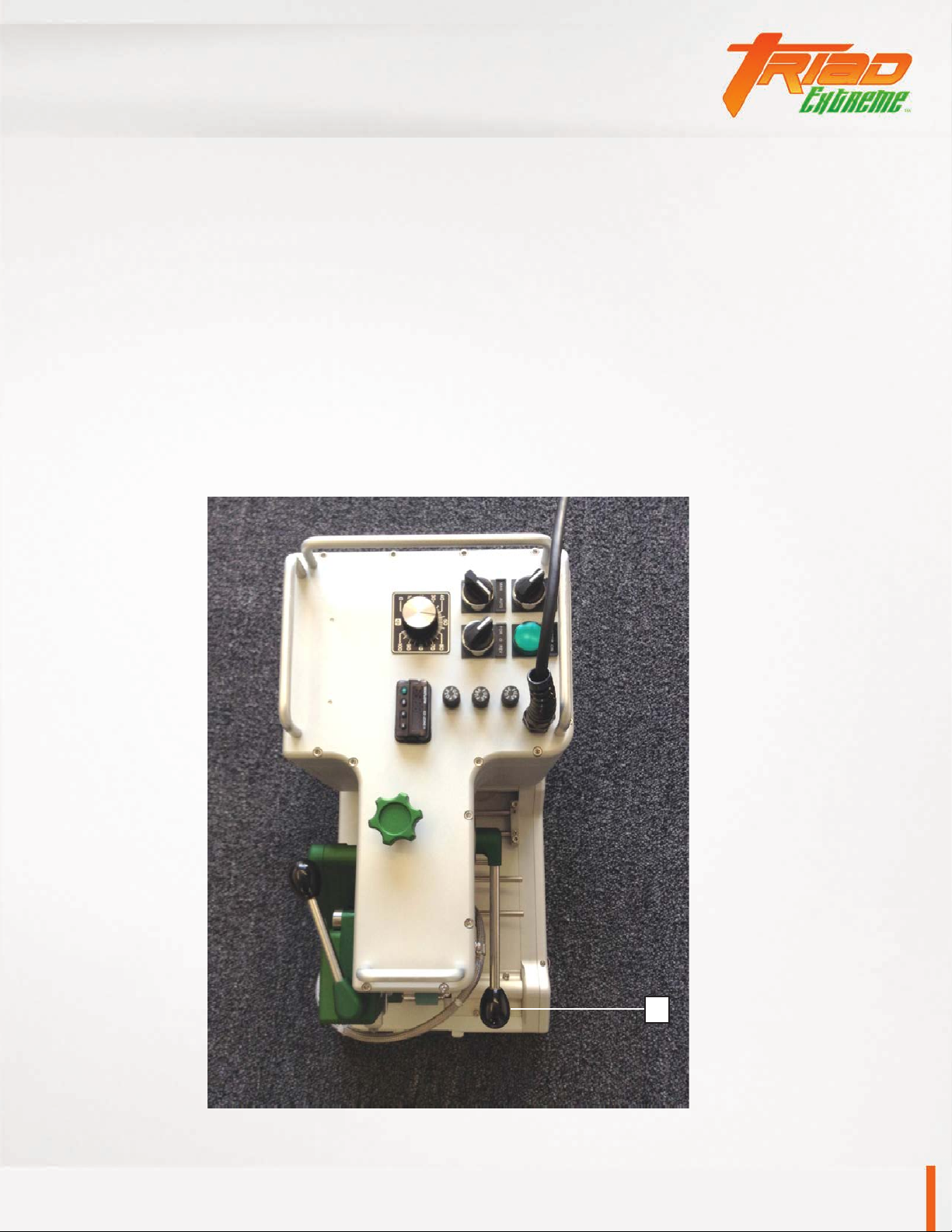
3.0 Operating Instructions
The following procedures should be followed only after you have followed the Wedge Adjustment and
Guide adjustment procedures.
1. Pull up on Red Power Switch #3 to turn machine on. The Green Power Light #4 will go on with a
one second delay. The Green light will remain on as an indicator that you have power to the ma-
chine. (Push down on Red Power Switch #3 to turn machine off)
2. Temperature Controller #7 will come on with a 1-2 second delay after Green Power Light goes on.
Units are set in celsius at the factory. Press the Set Button and hold, now press the up or down
button until you reach your desired temperature. Heat up time is only one to two minutes. Do not
adjust heat over 510 degrees C. For sample welds, set controller to 400 degrees C. This may not
be your final setting.
3. Set For/Rev Switch #5 to Forward position. This indicates direction of machine and drive/pressure
roller movement.
4. Set Man/Auto Switch #2 to Auto position. This will engage or start Drive/Pressure rollers when
wedge is moved into welding position.
5. Swing Drive Wheel Assembly #10 under bottom Pressure Roller. This will make the machine move
or automatic. With Drive Wheel Assembly out, the machine can be used in a stationary mode.
6. #1 is the Speed Control. It is adjustable from 0-30 feet per minute. Normal setting will be in the
30 to 60 range, for 12-30 mil goods.
7. #8 is the Pressure Knob. It can be adjusted for more or less pressure, depending on the thickness
of material.
8. Insert material into the machine with proper guides installed and close Pressure Wheel Handle #9.
9. Swing Wedge Engagement Handle #11 in toward the machine, this will automatically start forward
motion of the Triad and engage wedge with material.
10. Adjust speed control up or down until you can verify you are getting a proper weld.

Instruction Manual
Page 8CHAPTER 4 MATERIAL GUIDES
4.0 Material Guides
All Guides shown below are included with the purchase of the standard machine. Each guide will give
you a specific type of weld and more. You can only use one guide system at a time.
The Top Guide will be used with all three different welding functions, overlap, hem and prayer
welds. All Guides are adjustable.
To achieve a precise weld with no loose flap on top or bottom of sheet, guides should be adjusted so
that they are even with the width of wedge, or welding area
Overlap Guide
Top Guide
Hem Guide
Prayer or Fin Guide

Instruction Manual
Page 9 CHAPTER 5 WELDING
5.0 Welding
5.1 Overlap Weld
Attach Overlap Guide #1 to base plate with the two screws provided. Loosen screw (A) to adjust bottom side
of overlap for proper alignment and re-screw.
5.2 Hem Weld
Slide Hem Guide #2 onto the three stainless rods up to the outer Horn Guide #3 (Diagram #1), leaving
enough area between the two so material will slide easily. Tighten thumbscrew (B) (Diagram #1), this will
allow the outer Horn guide and Hem guide to move as one. This dictates the size of the hem to be welded.
Push on Hem Slide #4 (Diagram #2) to achieve desired hem width or size. When this is done, tighten thumb-
screws (C) (Diagram #1) to lock in place.
Instruction Manual
Page 10
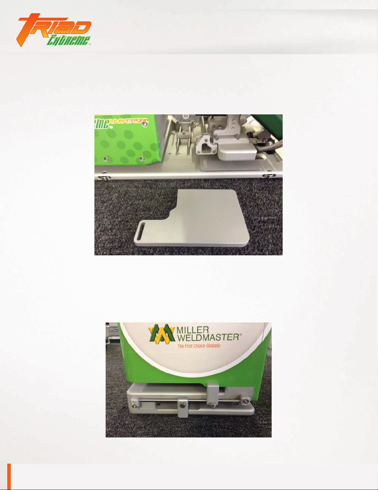
5.3 Prayer or Fin Weld
Position the Prayer Guide #5 under the Welding Horn, placing the key way into the slot. Fasten with screw
provided once proper alignment is completed.
5.4 Front Guides
Front Guides #6 are adjustable to pre-align material before you reach the welding process. This will help
the operator in feeding material into machine properly.
CHAPTER 5 WELDING

Instruction Manual
Page 11 CHAPTER 6 GENERAL MAINTENANCE
6.0 General Maintenance
General maintenance should be performed annually to your Triad Extreme Welder.
Chain tension should be checked to alleviate excessive wear to the chains and sprockets. Using a
foaming chain lubricant will cling to the chain and extend chain life.
The pinch rollers should be replaced if there are cuts, flat spots, burn marks etc.
Wedge adjustment should be checked daily before performing any welding. The operator should
be familiar with all wedge adjustments to get the best weld quality. Check for any loose hardware.
Loose hardware can alter the wedge adjustment with every engagement.

Instruction Manual
Page 12CHAPTER 7 WEDGE CLEANING AND HONING
7.0 Wedge Cleaning and Honing
For accurate welds and longer wedge life, the wedge should be cleaned and honed on a regular basis.
CLEANING: Wedge cleaning should be done daily. There are two ways to clean the wedge.
1. With the Pressure Rollers in the up position and the wedge in the weld position, use the Brass Brush
provided and clean wedge top and bottom. This can be done after every weld or as needed.
2. The second method of cleaning the wedge is to increase the temperature to 510 degrees C for 5-10
minutes. This will burn the residue on the wedge and it will flake off. Use the Brass Brush to re-
move.
HONING: Wedge Honing should be done if there are signs of wear on the wedge. This is evident with
uneven welds, rounding edges or corners on the wedge.
1. Install both smooth steel rollers on machine, (do not hone the wedge with the Silicone rollers on
machine).
2. Turn the forward/reverse switch to reverse position.
3. Swing wedge into weld position and close rollers.
4. Take the fine Emery Cloth provided, and run it back through the rollers on top of the wedge. Repeat
this step on the bottom of the wedge.
5. Repeat step 4 top and bottom until there is even wear the full length of wedge.
6. If Honing does not true up the wedge, refer to Wedge Adjustment section. A combination of honing
and adjustment may be necessary.
Emery Cloth
Instruction Manual
Page 13 CHAPTER 8 WEDGE ADJUSTMENT
8.0 Wedge Adjustment
Proper wedge alignment is essential to achieve a proper weld. Units are preset at the factory.
Sample welds should be made prior to actual use of the machine.
If sample welds are good only on one side or the other, or only partially welded, this means the
wedge is not aligned or square to the rollers, and alignment adjustment is needed.
Unplug unit from power source and make sure the wedge is cool before you work on the machine.
1. Pull Pressure Roller Handle #1 down. This will close Pressure Rollers.
1

Instruction Manual
Page 14
2. Swing Wedge Handle #2 in this will engage wedge with rollers. The wedge #4 should rest or
fit snug into the rollers #3 on both sides and should be centered.
CHAPTER 8 WEDGE ADJUSTMENT
4
2
3
8.0 Wedge Adjustment (Continued)

Instruction Manual
Page 15 CHAPTER 8 WEDGE ADJUSTMENT
3. To center wedge between rollers, turn screw #5, this will fine tune wedge up and down. Only a
1/8 or 1/4 turn is necessary. Do not overturn. Move Pressure Roller Handle up and down slowly
to check centering adjustment. Swing wedge handle in and out to ensure proper positioning.
5
4. Adjustment Screw #6 will move wedge on a center axis left and right. Loosen
Locking Screw #8 to make adjustment. Loosen Lock Nut #7, turn Adjustment
Screw clockwise to bring right side of wedge in and counterclockwise to bring left
side in. When adjusted properly, tighten Locking Screw and Lock Nut.
8
6
7
8.0 Wedge Adjustment (Continued)

Instruction Manual
Page 16
5. Wedge Stop Screw #9 will stop travel of wedge when positioning wedge in weld position.
Loosen Locknut #10 , turn Adjustment Screw in or out to proper position. The edge of the
wedge should fit snug and square into the rollers on each end.
Make a test weld before proceeding with job. Fine tuning your adjustments can be made while
wedge is hot. Do not run Hot Wedge into Silicone Rollers without material in machine for extended
periods, as it will distort the silicon.
Note: For thicker products (30mil and up) backing the wedge out may be necessary to allow room
for material.
10
9
CHAPTER 8 WEDGE ADJUSTMENT
8.0 Wedge Adjustment (Continued)

Instruction Manual
Page 17
9.0 Wedge Replacement
The wedge should be replaced when honing and adjustment is no longer effective. If heater failure occurs
after a period of time, the heaters may not be easily removed. The wedge and heater will most likely have
to be replaced together.
1. Unplug machine and make sure wedge is cool.
2. Remove Hanger Bracket Screw #11 and remove Wedge Housing Assembly #14.
3. Unscrew and detach Heater Connector #12.
4. Remove both Wedge Screws #13, and remove wedge.
5. Install new wedge with Wedge Screws. Attach Heater Connector and re-attach Wedge.
6. Center Housing with Screw #11 and tighten.
7. Wedge alignment may be necessary, please refer to Wedge Adjustment Section.
Note: Wedge Housing assembly will move back and forth in slot for #11 screw. Moving the Housing will
increase or decrease exposure of material to wedge for different preheat time or exposure. Thinner
products need little preheat, thicker material need more.
11
13
14
12
CHAPTER 9 WEDGE REPLACEMENT

Instruction Manual
Page 18
10.0 Wedge Installation
Install wedge on wedge mount
arm along with lead bracket
using two screws (note insert
photo). Position heater wires
properly on lead bracket and
gently close tabs to secure.
With wedge in engaged position,
use zip ties to collect heater
wires together. Note the wrap of
heater wires around upper pinch
roller arm and around back of
Triad.
CHAPTER 10 WEDGE INSTALLATION

Instruction Manual
Page 19
10.0 Wedge Installation (Continued)
CHAPTER 10 WEDGE INSTALLATION
Using clip & screw, attach
around heater wires and posi-
tion to body of Triad. Do not
fully tighten.
Electrically connect hot wedge
to receptacle on body of Triad.
When connected, make com-
fortable bend of heater wire and
position properly in clip. Swing
wedge in and out of welding po-
sition to make sure wrap around
back of Triad is comfortable.
When completed, tighten clip to
secure.

Instruction Manual
Page 20
11.0 Troubleshooting
Condition Possible Cause Corrective Action
Wedge doesn’t heat Fuse blown
Heater failed (220 Volt)
Control or relay failure
Loose wire
Diagnose wedge
Replace fuse
Replace wedge
Diagnose and replace control
Check wiring contacts
No drive, motor hums Chain break/binding
Pinch roller bearings
U joint shaft
Motor gears stuck (rare)
Find and repair or adjust failed chain
Replace bearings/shaft
Rebuild U joint shaft
Repair or replace motor
No drive, motor quiet Motor fuse failed caused by fabric or me-
chanical binding
Controller failure (usually associated with
control fuse blown)
Correct cause of binding
Replace fuse
Diagnose and replace controller
Wedge temp unsta-
ble
Controller programming
Heater failure (120 Volt)
Thermocouple failure
Reconfigure control.
Diagnose and replace wedge
Fuse blows (heater) Heater short or ground fault
Incorrect fuse value
Diagnose and replace wedge
Replace with correct fuse
Fuse blows (control) Controller failure
Short circuit or other wiring problem
Diagnose and replace failed control
Diagnose and correct wiring
Temp control display
blank, ER 4 (Triad) or ER in
(Spec)
No thermocouple signal
Thermocouple failure
Plug in and test wedge
Replace wedge
Check internal T/C wire
Temp control display
shows other ER code
Triad control (935) all errors are T/C based,
Spec control (SD) see control manual
Plug in and test wedge
Check control configuration
Only one pinch roller is
turning
Chain failure (Triad)
Belt failure (Spec)
Gear or sprocket spun
Repair or replace belt or chain
Replace shaft assembly
Pinch roller handle doesn’t
lift completely
Cam roller at apex of travel in cam plate Rotate wedge height adjustment bolt about
180° and readjust wedge center
CHAPTER 11 TROUBLESHOOTING
Table of contents
Other Miller Weldmaster Welding System manuals

Miller Weldmaster
Miller Weldmaster Impulse 3.0 Extreme User manual

Miller Weldmaster
Miller Weldmaster T600 Extreme User manual

Miller Weldmaster
Miller Weldmaster T-100 User manual

Miller Weldmaster
Miller Weldmaster 112 Extreme User manual

Miller Weldmaster
Miller Weldmaster 112 Extreme User manual

Miller Weldmaster
Miller Weldmaster Seamrover DD User manual

Miller Weldmaster
Miller Weldmaster T3 Extreme User manual

Miller Weldmaster
Miller Weldmaster Extreme T300 User manual


