Sua ionTig 200 Pulse PFC User manual

ionTig 200 Pulse PFC
Copyright © Mundaka Welding & Gases, Inc.
ionTig 200 Pulse PFC
INVERTER - DC PULSED TIG WELDER
OPERATION MANUAL
IMPORTANT: Read this Owner’s Manual Completely before attempting to use this
equipment. Save this manual and keep it handy for quick reference. Pay particular
attention to the safety instructions we have provided for your protection. Contact your
distributor if you do not fully understand this manual.

ionTig 200 Pulse PFC
Copyright © Mundaka Welding & Gases, Inc.
2
CONTENT
1. SAFETY............................................................................................................................................ 3
1.1 Signal Explanation............................................................................................................................ 3
1.2 The Knowledge of Electric and Magnetic Fields............................................................................6
2. Overview..........................................................................................................................................7
2.1 Brief Introduction.............................................................................................................................. 7
2.3 Volt-Ampere Characteristic............................................................................................................ 10
3. Installation and Adjustment ..........................................................................................................11
3.1 Parameters .......................................................................................................................................11
3.2 Duty cycle and Over-heat............................................................................................................... 12
3.3 Movement and Placement.............................................................................................................. 12
3.4 Power supply input connection..................................................................................................... 13
3.5 Polarity Connection (MMA)............................................................................................................ 13
3.6 Assembling the equipment (TIG)................................................................................................... 14
4. Operation....................................................................................................................................... 14
4.1 Layout for the panel........................................................................................................................ 14
4.2 Control panel................................................................................................................................... 15
4.3 Argon Arc Welding Operation........................................................................................................ 19
4.3.1 TIG welding (4T operation).......................................................................................................... 19
4.3.2 TIG welding (2T operation).......................................................................................................... 20
4.4 Welding Parameters........................................................................................................................ 22
4.4.1 Joint forms in TIG/MMA............................................................................................................... 22
4.4.2 The explanation of welding quality............................................................................................. 22
4.4.3 TIG Parameters Matching............................................................................................................ 23
4.5 Operation Environment.................................................................................................................. 25
4.6 Operation Notices........................................................................................................................... 25
5. Maintenance & Troubleshooting.................................................................................................. 26
5.1 Maintenance.................................................................................................................................... 26
5.2 Troubleshooting.............................................................................................................................. 27
5.3 Electrical principle drawing ........................................................................................................... 30

ionTig 200 Pulse PFC
Copyright © Mundaka Welding & Gases, Inc.
3
1. SAFETY
1.1 Signal Explanation
Welding may damage your body or others, so please take protection
measure in operation.
Only ones who are trained professionally can install, debug, operate,
maintain and repair the equipment.
Do not maintain and repair the machine when the machine is
connected with power.
THE ROTATING PARTS MAY BE DANGEROUS
Keep all equipment safety guards, covers and devices in position and
in good repair. Keep hands, hair, clothing and tools away from V-belts,
gears, fans and all other moving parts when starting, operating or
repairing equipment.
Do not put your hands near the engine fan. Do not attempt to override
the governor or idler by pushing on the throttle control rods while the
engine is running.
Use only compressed gas cylinders containing the correct shielding
gas for the process used and properly operating regulators designed
for the gas and pressure used. All hoses, fittings, etc. should be
suitable for the application and maintained in good condition.
Always keep cylinders in an upright position securely chained to an
undercarriage or fixed support.
Cylinders should be located:
oAway from areas where they may be struck or subjected to
physical damage.
oA safe distance from arc welding or cutting operations and any
other source of heat, sparks, or flame.
Never allow the electrode, electrode holder or any other electrically
“hot” parts to touch a cylinder.
Keep your head and face away from the cylinder valve outlet when
opening the cylinder valve.
Valve protection caps should always be in place and hand tight except
when the cylinder is in use or connected for use.

ionTig 200 Pulse PFC
Copyright © Mundaka Welding & Gases, Inc.
4
FUMESAND GASES CAN BE DANGEROUS
Welding may produce fumes and gases hazardous to health. Avoid
breathing these fumes and gases. When welding, keep your head out
of the fume. Use enough ventilation and/or exhaust at the arc to keep
fumes and gases away from the breathing zone. When welding with
electrodes which require special ventilation such as stainless or hard
facing or on lead or cadmium plated steel and other metals or coatings
which produce highly toxic fumes, keep exposure as low as possible
and below Threshold Limit Values using local exhaust or mechanical
ventilation. In confined spaces or in some circumstances, outdoors, a
respirator may be required. Additional precautions are also required
when welding on galvanized steel.
Do not weld in locations near chlorinated hydrocarbon vapors coming
from degreasing, cleaning or spraying operations. The heat and rays of
the arc can react with solvent vapors to form phosgene, a highly toxic
gas, and other irritating products.
Shielded gases used for arc welding can displace air and cause injury
or death. Always use enough ventilation, especially in confined areas,
to insure breathing air is safe.
Read and understand the manufacturer’s instructions for this
equipment and the consumables to be used, including the material
safety data sheet and follow your employer’s safety practices.
ARC RAYS CAN BURN.
Use a shield with the proper filter and cover plates to protect your eyes
from sparks and the rays of the arc when welding or observing open
arc welding.
Use suitable clothing made from durable flame-resistant material to
protect your skin and that of your helpers from the arc rays.
Protect other nearby personnel with suitable, non-flammable screening
and /or warn them not to watch the arc nor expose themselves to the
arc rays or to hot spatteror metal.
ionTig 200 Pulse PFC
Copyright © Mundaka Welding & Gases, Inc.
5
ELECTRIC SHOCK CAN KILL.
Never touch electrical parts.
Wear dry, hole-free gloves and clothes to insulate yourself.
Insulate yourself from work and ground using dry insulation. Make
certain the insulation is large enough to cover your full area of physical
contact with work and ground.
Take carefully when using the equipment in small place, falling-off and
wet circumstance.
Never close the machine power before installation and adjustment.
Ensure to install the equipment correctly and ground the work or metal
to be welded to a good electrical (earth) ground according the
operation manual.
The electrode and work (or ground) circuits are electrically “hot” when
the welder is on. Do not touch these “hot” parts with your bare skin or
wet clothing. Wear dry, hole-free gloves to insulate hands.
In semiautomatic or automatic wire welding, the electrode, electrode
reel, welding head, nozzle or semiautomatic welding gun are also
electrically “hot”.
Always be sure the work cable makes a good electrical connection with
the metal being welded. The connection should be as close as possible
to the area being welded.
Maintain the electrode holder, work clamp, welding cable and welding
machine in good, safe operating condition. Replace damaged
insulation.
Never dip the electrode in water for cooling.
Never simultaneously touch electrically “hot” parts of electrode holders
connected to two welders because voltage between the two can be the
total of the open circuit voltage of both welders.
When working above the floor level, use a safety belt to protect yourself
from a fall should you get a shock.
FIREAND EXPLOSION
Remove fire hazards from the welding area. If this is not possible,
cover them to prevent the welding sparks from starting a fire.
Remember that welding sparks and hot materials from welding can
easily go through small cracks and openings to adjacent areas. Avoid
welding nearhydraulic lines. Have a fire extinguisher readily available.

ionTig 200 Pulse PFC
Copyright © Mundaka Welding & Gases, Inc.
6
1.2 The Knowledge of Electric and Magnetic Fields
Electric current flowing through any conductor causes localized Electric and Magnetic Fields (EMF). The
discussion on the effect of EMF is ongoing all the world. Up to now, no material evidences show that
EMF may have effects on health. However, the research on damage of EMF is still ongoing. Before any
Where compressed gases are to be used at the job site, special
precautions should be used to prevent hazardous situation.
When not welding, make certain no part of the electrode circuit is
touching the work or ground. Accidental contact can cause overheating
and create a fire hazard.
Do not heat, cut or weld tanks, drums or containers until the proper
steps have been taken to insure that such procedures will not cause
flammable or toxic vapors from substances inside. They can cause an
explosion even though they have been “cleaned”.
Vent hollow castings or containers before heating, cutting or welding.
They may explode.
Sparks and spatter are thrown from the welding arc. Wear oil free
protective garments such as leather gloves, heavy shirt, cuff less
trousers, high shoes and a cap over your hair. Wear ear plugs when
welding out of position or in confined places. Always wear safety
glasses with side shields when in a welding area.
Connect the work cable to the work as close to the welding area as
practical. Work cables connected to the building framework or other
locations away from the welding area increase the possibility of the
welding current passing through lifting chains, crane cables or other
alternate circuits. This can create fire hazards or overheat lifting chains
or cables until they fail.
Hot parts can lead to burn.
Do not touch the hot parts.
Please use the torch after cooling or use the welding blow lamp.

ionTig 200 Pulse PFC
Copyright © Mundaka Welding & Gases, Inc.
7
conclusion, we should minimize exposure to EMF as few as possible.
In order to minimize EMF, we should use the following procedures:
Route the electrode and work cables together – Secure them with tape when possible.
All cables should be put away and far from the operator.
Never coil the power cable around your body.
Make sure welding machine and power cable to be far away from the operator as far as possible
according to the actual circumstance.
Connect the work cable to the work piece as close as possible to the area being welded.
The people with heart-pacemaker should be awayfrom the welding area.
2. Overview
2.1 Brief Introduction
ionTig 200 Pulse PFC arc welding machine adopts the latest pulse width modulation (PWM) technology
and insulated gate bipolar transistor (IGBT) power module, which can change work frequency to medium
frequency so as to replace the traditional hulking work frequency transformer with the cabinet medium
frequency transformer. Thus, it is characterized with portable, small size, light weight, low consumption
and etc.
The parameters of ionTig 200 Pulse PFC on the front panel all can be adjusted continuously and
sleeplessly, such as start current, crater arc current, welding current, base current, duty ratio, upslope
time, downslope time, pre-gas, post-gas, pulse frequency, AC frequency, balance, hot start, arc force
and arc length etc. When welding, it takes high frequency and high voltage for arc igniting to ensure the
success ratio of igniting arc.

ionTig 200 Pulse PFC
Copyright © Mundaka Welding & Gases, Inc.
8
ionTig 200 Pulse PFC Characteristics:
DC Pulsed TIG and MMA, adopt IGBT and advanced PWM technology
High performance MCU, Digital control, Digital display
Preset all parameters with hold process
HF/Lift TIG, current down slope and up slope, gas post-flow, Pulse Frequency
Intelligent protection: over-voltage, under-voltage, over-current, over-heat
1. For MMA, polarity connection can be chosen according to different electrodes,please refer to
§3.5;
2. For DC TIG, DCEP is used normally (workpiece connected to positive polarity, while torch
connected to negative polarity). This connection has many characters, such as stable welding arc, low
tungsten pole loss, more welding current, narrow and deep weld;
3. DC Pulsed TIG has the following characters: 1) Pulse heating. Metal in Molten pool has short
time on high temperature status and freezes quickly, which can reduce the possibility to produce hot
crack of the materials with thermal sensitivity. 2) The workpiece gets little heat. Arc energy is focused. Be
suitable for thin sheet and super thin sheet welding. 3) Exactly control heat input and the size of the
molten pool. The depth of penetration is even. Be suitable for welding by one side and forming by two
sides and all position welding for pipe. 4) High frequency arc can make metal for microlite fabric,
eliminate blowhole and improve the mechanical performance of the joint. 5) High frequency arc is
suitable for high welding speed to improve the productivity.
TP-series welding machine is suitable for all positions welding for various plates made of stainless
steel, carbon steel, alloyed steel, titanium, magnesium, cuprum, etc., which is also applied to pipe
installment, mold mend, petrochemical, architecture decoration, car repair, bicycle, handicraft and
common manufacture.

ionTig 200 Pulse PFC
Copyright © Mundaka Welding & Gases, Inc.
9
MMA——Manual MetalArc welding
PWM——Pulse-Width Modulation
IGBT——Insulation Gate Bipolar Transistor
TIG——Tungsten Insert Gas welding
2.2 Working Principle
The working principle of TP- series welding machines is shown as the following figure. Single phase
work frequency AC 220V (50 Hz) is rectified into DC (about 380V), then is converted to medium
frequency AC (about 20KHz) by inverter device (IGBT), after reducing voltage by medium transformer
(the main transformer) and rectifying by medium frequency rectifier (fast recovery diode), and is
outputted by inductance filtering. The circuit adopts current feedback control technology to insure current
output stably. Meanwhile, the welding current parameter can be adjusted continuously and sleeplessly to
meet with the requirements of welding craft.
Rectify Inverter
Medium
frequency
transformer
Medium
frequency
rectify
Hall device
Current positive-
feedback control
DC AC DCAC DC
380V,50HZ
Three-phases
AC
Single-Phase AC

ionTig 200 Pulse PFC
Copyright © Mundaka Welding & Gases, Inc.
10
2.3 Volt-Ampere Characteristic
ionTig 200 Pulse PFC welding machine has an excellent volt-ampere characteristic, whose graph is
shown as the following figure. The relation between the conventional rated loading voltage U2 and the
conventional welding current I2 is as follows:
When I2≤600A,U2=10+0.04I2(V); When I2¬>600A,U2=34(V).

ionTig 200 Pulse PFC
Copyright © Mundaka Welding & Gases, Inc.
11
3. Installation and Adjustment
3.1 Parameters
Models
Parameters
TIG 200 DC PULSE PFC
Input power
Single phase,110V,50/60Hz
Single phase,220V, 50/60Hz
TIG
MMA
TIG
MMA
Rated input current(A)
24.5
33
20
32
Rated input power(KW)
2.7
3.6
4.4
7
Power factor
0.99
0.99
Welding current range(A)
5~120
5~200
Max no-load voltage(V)
24
66
24
66
Efficiency
≥85%
≥85%
Duty cycle (40 ℃ , 10
minutes),see §3.2)
90% 120A
60% 120A
50% 200A
35% 200A
100% 105A
100% 95A
100% 160A
100% 135A
Protection class
IP23
Insulation class
H
Dimensions of Machine
(L×W×H)(mm)
450×135×250
Weight(Kg)
9
Note: The above parameters are subject to change with the improvement of machines.
ionTig 200 Pulse PFC
Copyright © Mundaka Welding & Gases, Inc.
12
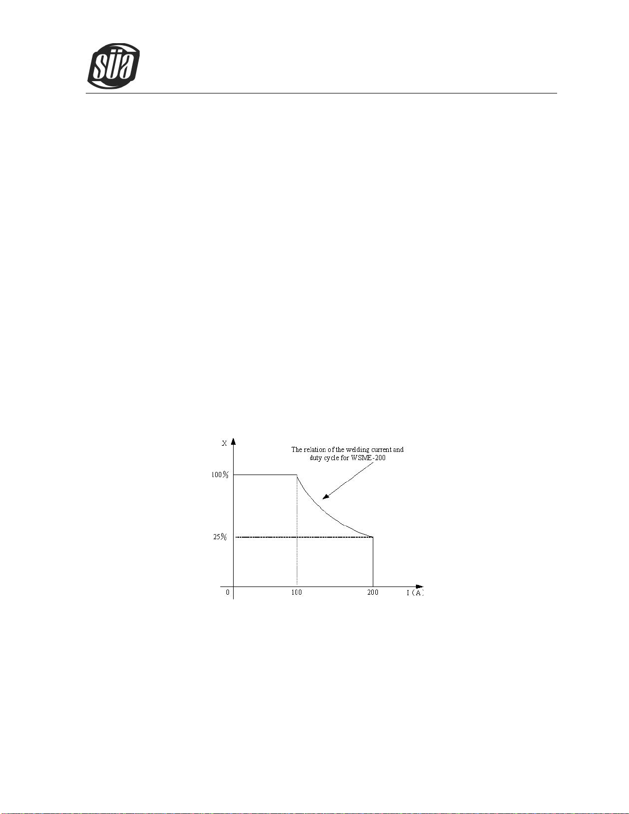
3.2 Duty cycle and Over-heat
The letter “X” stands for duty cycle, which is defined as the proportion of the time that a machine
can work continuously within a certain time (10 minutes). The rated duty cycle means the proportion of
the time that a machine can work continuously within 10 minutes when it outputs the rated welding
current.
The relation between the duty cycle “X” and the output welding current “I” is shown as the right
figure.
If the welder is over-heat, the IGBT over-heat protection unit inside it will output an instruction to cut
output welding current, and brighten the over-heat pilot lamp on the front panel. At this time, the machine
should be relaxed for 15 minutes to cool the fan. When operating the machine again, the welding output
current or the duty cycle should be reduced.
3.3 Movement and Placement
Please take care for the welder when moving it, and do not make it sloped.
It also can be moved by the handle on the topof the welder. Place the welder well when moving it to

ionTig 200 Pulse PFC
Copyright © Mundaka Welding & Gases, Inc.
13
the right position. When the machine gets to the destination, it needs to be fixed up to avoid gliding.
When using forklift, its arm length must be long enough to reach the outside so as to ensure lifting
safely.
The movement may result in the potential danger or substantive hazard, so please make sure
that the machine is on the safe position before using it.
3.4 Power supply input connection
ionTig 200 Pulse PFC welding machines’power supply connects to 220V.
When the power supply voltage is over the safe work voltage, there are over voltage and under
voltage protection inside the welder, the alarm light will on, at the same time, the current output will
be cut off.
If the power supply voltage continually goes beyond the safe work voltage range, it will shorten the
welder life-span.The below measures can be used:
Change the power supply input net. Such as, connect the welder with the stable power supply
voltage of distributor;
Induce the machines using power supply in the same time;
Set the voltage stabilization device in the front of power cable input.
3.5 Polarity Connection (MMA)
MMA (DC): Choosing the connection of DCEN or DCEP according to the different electrodes.
Please refer to the electrode manual.
WTL
workpiec
e
electrode
DC POSITIVE
CONNECTION
Welding holder
TP-315
WTL
workpiec
e
Welding holder
electrode
DC NEGATIVE
CONNECTION
TP-315
TIG 200
DC PULSE
TIG 200
DC PULSE
ionTig 200 Pulse PFC
Copyright © Mundaka Welding & Gases, Inc.
14
3.6 Assembling the equipment (TIG)
Work piece is connected to the positive electrode of welding machine, and welding torch is
connected to the negative electrode, which is called DC POSITIVE CONNECTION; otherwise,
that is called DC NEGATIVE CONNECTION. Generally, it is usually operated in DC POSITIVE
CONNECTION in TIG welding mode.
The control cable of torch switch consists of 2 wires, pedal control of 3 wires and the aero
socket has 14 leads.
Consumable parts for TIG torch, such as tungsten electrode、tip、gas nozzle、electrode shield
(short/long) , please enquire us by mail or phone according to the accessory codes.
When ionTig 200 Pulse PFC welding machines are operated in HF ignition method, the ignition
spark can cause interferences in equipment near the welding machine. Be sure to take
specially safety precautions or shielding measures.
4. Operation
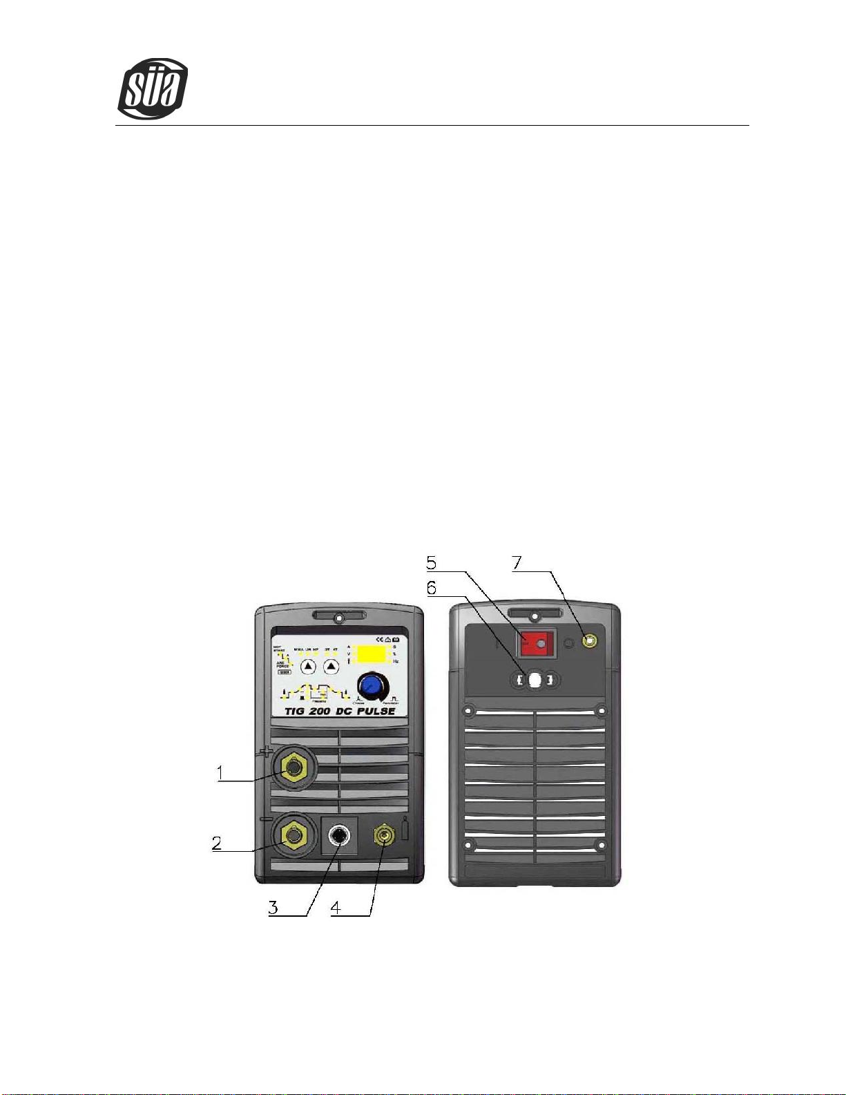
4.1 Layout for the panel

ionTig 200 Pulse PFC
Copyright © Mundaka Welding & Gases, Inc.
15
(1) Positive output: The welder’s positive polarity output.
(2) Negative output: The welder’s negative polarity output.
(3) Aero socket: Is connected to torch switch control wire.(It has 14 leads and lead 8 - lead 9
are connected to torch switch control wire).
(4) Shield gas connector: Is connected to the gas input pipe of torch.
(5) Power source switch: Switch to “ON”, the welder is turned on, while switch to “OFF”, the
welder is turned off.
(6) Power source input: To connect power source.
(7) Shield gas input joint: To connect one head of the gas hose while the other head of which is
connected to argon gas cylinder.
.
4.2 Control panel
Overview
The key feature of the control panel is the logical way in which the controls are arranged. All the main
parameters needed for day-to-day working can easily be
-selected with the keys.
-altered with the adjusting dial.
ionTig 200 Pulse PFC
Copyright © Mundaka Welding & Gases, Inc.
16
-shown on the display during welding.
The illustration below shows an overview of the main settings needed for day-to-day working, using
the TIG 200 DC PULSE control panel as an example. You will find a detailed description of these settings
in the following section.
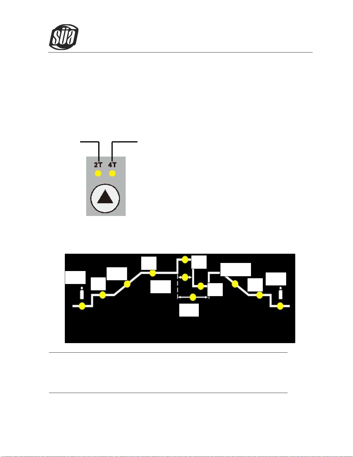
(1)TIG mode selecting key
2-step mode 4-step mode
(2)Parameter select and adjust
Push the encoder to select the parameter if the parameter indicator lights up, then the selected parameter can
be altered on adjusting dial.
Available parameters where 2T and 4T mode have been selected:
Tpr Gas pre-flow time
Unit S
Setting range 0.1—1
Factory setting
Tpr
Is
Tup
Iw
Ic
Tpo
Tdown
Fp
Dcy
Ib
Iw

ionTig 200 Pulse PFC
Copyright © Mundaka Welding & Gases, Inc.
17
Is Starting current (only with 4T)
Unit A
Setting range 5—100%of main current Iw
Factory setting
Tup Upslope time
Unit S
Setting range 0.0—2.0
Factory setting
Iw Welding current
Unit A
TIG 200 DC PULSE 5—200;
TIG 200 DC PULSE PFC 5—200;
TIG 180 DC PULSE PFC 5—180;
Ib Base current
Unit A
TIG 200 DC PULSE 5—200;
TIG 200 DC PULSE PFC 5—200;
TIG 180 DC PULSE PFC 5—180;
Important! Only selectable when “pulse key”has been pressed.
Dcy Ratio of pulse duration to base current duration
Unit %
Setting range 5—100
Factory setting
Important! Only selectable when “pulse key”has been pressed.
Fp Pulse frequency
Unit Hz
Setting range 0.5—200
Factory setting
Important! Only selectable when “pulse key”has been pressed.
Tdown Downslope time
ionTig 200 Pulse PFC
Copyright © Mundaka Welding & Gases, Inc.
18
Unit S
Setting range 0—10
Factory setting
Ic Crater arc current (only with 4T)
Unit S
Setting range 5—100% of main current Iw ;
Factory setting
Tpo Gas post-flow time
Unit S
Setting range 0.0—10.0
Factory setting
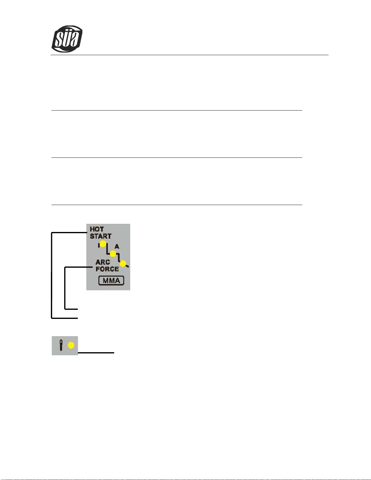
(3) Rod electrode (MMA) welding parameter
Parameter Setting range
Arc force 0-10
Hot start 0-10
(4) Power/Alarm indicator
Light up if the welder overheat.
(5) Welding current and other parameter display
Before start of welding Indicate the open-circuit voltage when you push the enconder for 3s and the display
shows the pre-set value of Tpr ,Is ,Tup,Iw,Dcy,Iw,Fp,Ib,Tdown,Ic,Tpo . After the start of welding, display
shows the present actual value of the welding current.
The control panel indicates which position has been reached in the welding process by brightening the light.
ionTig 200 Pulse PFC
Copyright © Mundaka Welding & Gases, Inc.
19
NOTE:
Only the Iw of TIG or the welding current of MMA can be adjust when welding.
4.3 Argon Arc Welding Operation
4.3.1 TIG welding (4T operation)
The start current and crater current can be pre-set. This function can compensate the possible
crater that appears at the beginning and end of the welding. Thus, 4T is suitable for the welding of
medium thickness plates.
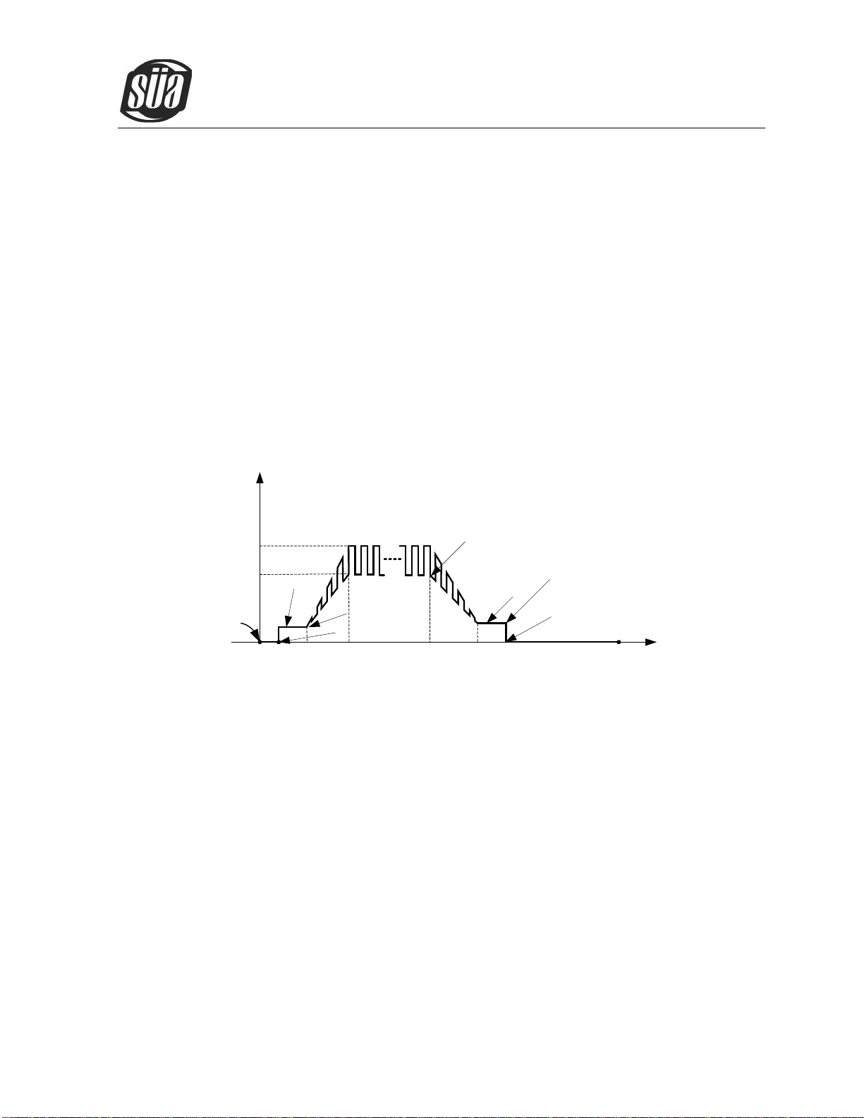
Pulsed TIG long welding (4T):
t( s)
0
I( A)
Loosen the
switch
t1 t5 t7
Striking success
Stop arc
t3 t4
Base current setting
value
t2 t6
Loosen the
switch
Repress down the
switch
Start
current Crater
current
Welding current (peak
current) setting value
Press and hold the
welding gun switch
Introduction:
0:Press and hold the gun switch, Electromagnetic gas valve is turned on. The
shielding gas starts to flow;
0~t1:Pre flow time, adjustment range of pre flow time :0.0~2.0S;
t1:Striking success, adjustment range of start current: 5~180A(200A);
t2:Loosen the gun switch, the output current slopes up from start current; if the output
pulse function is turned on, the output current is pulsed;
t2~t3:Output current slopes up to the setting current value; adjustment range of up slope
time 0~10.0S ;
t3~t4:Welding process. During this period, the gun switch isloosen;
Note: If the output pulse function is turned on, the output current is pulsed. If the output pulse
function is turned off, the output current is the welding current(Iw);

ionTig 200 Pulse PFC
Copyright © Mundaka Welding & Gases, Inc.
20
t4:Repress down the gun switch, the output current slopes down to crater current; if the
output pulse function is turned on, the slope down current is pulsed;
t4~t5:Down slope time,adjustment rang of down slope time: 0~10.0S;
t5~t6:Crater current holds time; adjustment range of crater current: 5~180A(200A);
t6:Loosen the gun switch, stop arc, and keep on argon flowing;
t6~t7:Post flow time, adjustment range of post flow time: 0.0~10.0S;
t7:Electromagnetic valve is closed and stop argon flowing. Welding is finished.
4.3.2 TIG welding (2T operation)
t( s)
0
I( A)
Loosen the
welding gun
switch
Press and hold the
welding gun switch
t1 t5
Striking
success Stop arc
t3 t4
Base current setting
value
t2
Welding current (peak
current) setting value
5A
Introduction:
0:Press and hold the gun switch, Electromagnetic gas valve is turned on. The
shielding gas starts to flow;
0~t1:Pre flow time, adjustment range of pre flow time :0.0~2.0S;
t1~t2:Striking success, the output current slopes up to the setting current from minimum
current (5A); if the output pulse function is turned on, the slope up current is pulsed;
t2~t3:During the whole welding process, the gun switch is pressed and held without
releasing;
Note: If the output pulse function is turned on, the output current is pulsed. If the output pulse
function is turned off, the output current is DC current;
t3:Loosen the gun switch, the output current slopes down; if the output pulse function is
turned on, the slope down current is pulsed;
t3~t4:The output current slopes down to minimum current (5A), stop arc; adjustment range
of down slope time: 0~10.0S;
Table of contents
Other Sua Welding System manuals


Popular Welding System manuals by other brands


Brugg Pipesystems
Brugg Pipesystems ewelcon CAW04 operating instructions

BriskHeat
BriskHeat ACR 3 instruction manual

Parkside
Parkside PFDS 120 A2 Assembly, operating and safety instructions, Translation of the original instructions

WIA
WIA WELDMATIC 600 user manual

SIWM
SIWM Paris 500 operating instructions

Sealey
Sealey POWERMIG2500 instructions

Sumig
Sumig NANOCUT 40 operating manual

Autowel
Autowel NICE-80DP user manual

Miller Electric
Miller Electric Legend AEAD-200LE Technical manual

Migatronic
Migatronic PILOT 1800 instruction manual

ESAB
ESAB Precision Plasmarc Installation, operation and maintenance manual for residential installation
 Operator's manual")
Jasic
Jasic CUT80 (L205) Operator's manual