Extractor Corporation SUITMATE User manual

©2017 Extractor Corporation
115-V 20-Amp 60-Hz SUITMATE
®
Unit
1
INSTALLATION INSTRUCTIONS
115-V 20-Amp 60-Hz Self-Timed Unit
The SUITMATE®Swimsuit Water Extractor has been designed and manufactured with safety as the primary
consideration. Therefore, it is important that the unit be installed correctly. It is also important that the
installation comply with all local building codes and regulations. Please consult your local licensed plumbing
and electrical engineers or contractors about your installation. Read the entire INSTALLATION
INSTRUCTIONS before beginning your installation. Remember: DO IT RIGHT and DO IT SAFE!
PROPER LOCATION FOR THE SUITMATE®UNIT
Following is a list of factors to consider in determining a location for the SUITMATE®unit.
1) The unit should be located in an area that is near where people remove and rinse out their swimsuits.
2) The unit should NOT be located in a cluttered area or where it is exposed to direct shower water or
water hose down.
3) The unit should be mounted on a wall structure that will support the unit’s approximate 55 pounds (25kg)
hanging weight plus the added weight or pressure of people leaning on the unit. Consult the PROPER
WALL MOUNTING section of these instructions to determine an appropriate location.
4) There should be a means to dispose of the wastewater from the unit. Consult the PROPER DRAINAGE
section of these instructions (page 5) to determine an appropriate location.
5) The unit should be wired to a 115-V(AC) 20-Amp 60-Hz dedicated circuit. Consult the PROPER
ELECTRICAL CONNECTIONS section of these instructions (page 5) to determine proper location.
PROPER WALL MOUNTING OF THE SUITMATE®UNIT
The SUITMATE®unit should be mounted to the wall with the Wall Mount Bracket that is provided with the unit.
The UTILITIES LOCATION DIAGRAM (page 8) shows the recommended location for the mounting holes, the
electrical service, and the wastewater outlet (if utilized). The Wall Mount Bracket must be secured to a wall
stud, or to concrete block or cinder block wall.
WARNING!
Anchors in drywall are not sufcient to mount the SUITMATE®unit.
Locating and Securing the Wall Mount Bracket to the Wall
The suggested height from the oor to the top of the SUITMATE®
unit is 42 inches (107cm). At least an additional 10 inches (25.5cm)
of clearance above the SUITMATE®unit is needed for the
opening and closing of the lid. The upper center hole of the Wall
Mount Bracket should be 38 +/- 1/16 inches (96.5cm +/- 2mm)
from the oor. The top of the Wall Sign should be 60 +/- 1/16 inches
(152.5cm +/- 2mm) above the oor and centered over the
SUITMATE®unit. Determine a location on the wall that provides
adequate clearance, a strong and secure place for the
Wall Mount Bracket as well as easy access to electrical and
drainage connections.
WARNING!
The Wall Mount Bracket must be level after it is secured to the wall.
CHECK WITH LEVEL
USE APPROPRIATE FASTENERS
FOR YOUR APPLICATION
TO WALL

©2017 Extractor Corporation
115-V 20-Amp 60-Hz SUITMATE
®
Unit
2
To secure the Wall Mount Bracket, center the bracket at the desired location and mark the locations of the two
center holes. Secure the Wall Mount Bracket at the center holes using fasteners appropriate for your
conditions. All fasteners must be capable of supporting 55 pounds (25kg) in addition to the added weight or
pressure of people leaning on the unit. Make certain the Wall Mount Bracket is level. Next secure the outer
holes of the Wall Mount Bracket to the structure using fasteners appropriate to your conditions. After the
bracket has been properly anchored to the wall and the electrical and drainage requirements have been
allowed for, the SUITMATE®unit is ready to be mounted to the wall.
Mounting the SUITMATE®Unit to the Wall
Remove the SUITMATE®unit from its shipping box. Remove and discard the packaging material that is
protecting the SUITMATE®unit, including the material protecting the SUITMATE®motor. The upper back lip of
the SUITMATE®unit should be lowered down and centered on the Wall Mount Bracket. After the unit is cen-
tered, push down on the back of the unit to make certain that it is securely wedged onto the bracket. Make
certain the unit is level. If it is not level, remove the unit, adjust the Wall Mount Bracket and re-hang the unit. A
level installation is necessary to minimize vibration and insure proper drainage of wastewater. Finish securing
the unit to the wall using appropriate fasteners and anchors on the lower mounting channel at the bottom rear
of the unit. This will prevent the unit from being lifted from the bracket or being moved.
Note: Several holes in the lower mounting bracket may be obstructed by the GFCI Cover. Remove the GFCI
cover to provide access to these holes.
SUITMATE®UNIT
(front)
WALL MOUNT
BRACKET
USE APPROPRIATE ANCHORS AND
FASTENERS TO MOUNT THE UNIT
FOR YOUR SPECIFIC INSTALLATION
CUTAWAY VIEW OF SUITMATE®UNIT
FLOOR
PRESS HERE TO FIRMLY
SET SUITMATE®UNIT
WALL
WALL
MOUNT
BRACKET
UPPER
BACK
LIP OF UNI
TEASE
UNIT
OVER
BRACKET
AND
LOWER
MOUNTING
SCREWS

©2017 Extractor Corporation
115-V 20-Amp 60-Hz SUITMATE
®
Unit
3
PROPER DRAINAGE FOR THE SUITMATE®UNIT
Note: Strictly follow all applicable local plumbing codes and regulations.
TO A FLOOR DRAIN
Drainage of the wastewater to a oor drain should be done ONLY in an area where the oor is normally wet.
DO NOT drain water across a oor where people do not expect to encounter a wet and slippery condition. The
SUITMATE® unit comes with a short exible drain extension tube connected with a stainless steel hose clamp
to its drain tailpiece.
WARNING!
The drain tube that comes with the unit must not be removed unless the unit is
connected to an approved wastewater outlet or the factory-supplied tube is
replaced with another tube according to the following instructions.
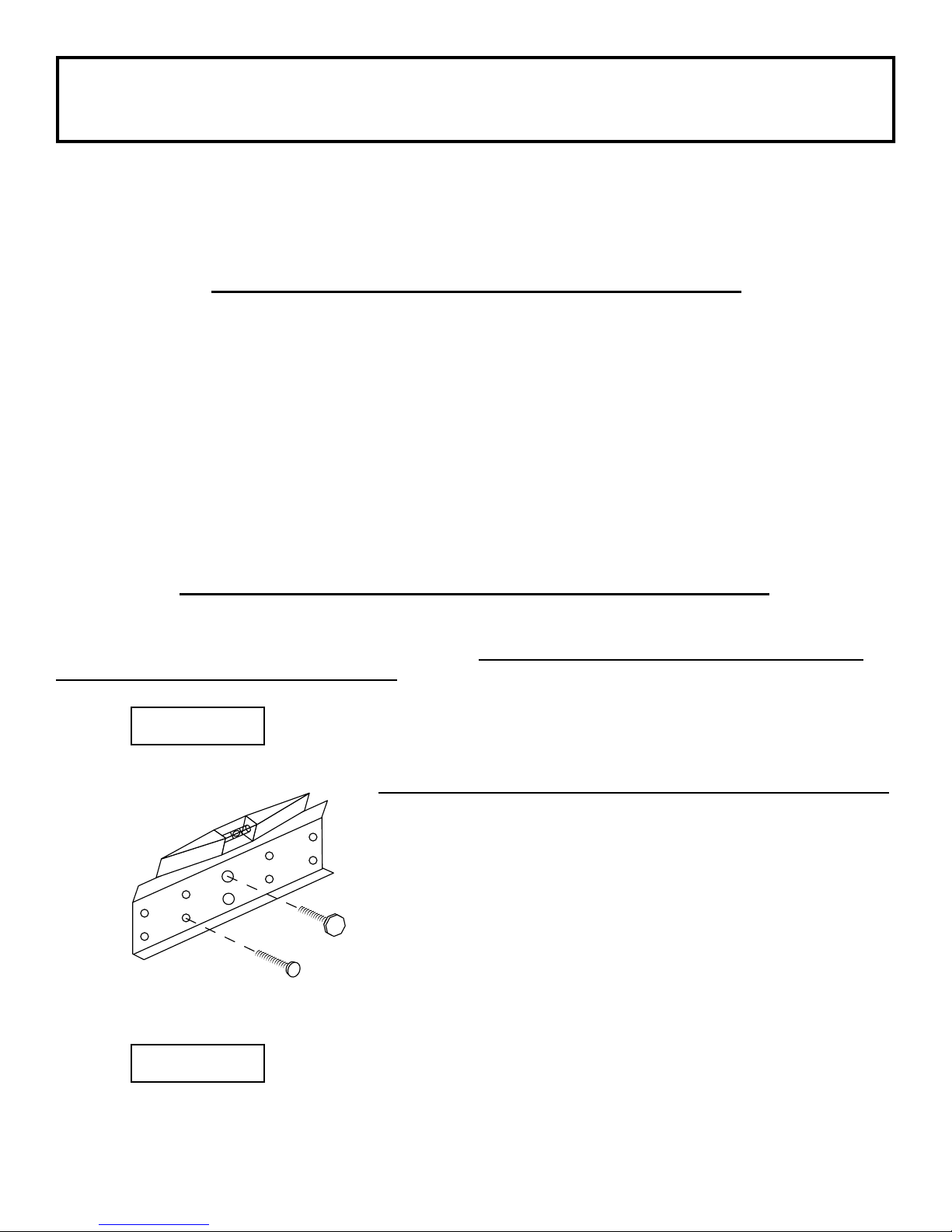
Replacing the Factory Drain Tube with a Longer Drain Tube
Use a 1-1/4 inch (31.75 mm) I.D. drain tube with a smooth interior that will not crimp or collapse. Use the
stainless steel hose clamp that is provided with the factory exible oor drain extension tube to secure the
replacement tube to the unit’s drain tailpiece. Route the drain tube so that it is never higher than the bottom of
the SUITMATE® unit and always slopes down. Secure the drain tube to the wall or oor with properly sized “U”
clamps so it cannot be maneuvered to trap wastewater. Cut off the end of the drain tube on an angle to help
prevent it from being blocked by the oor, wall, or some other object. Upon completion of the installation,
check to make certain that there is a free ow of water from the drain tube extension.
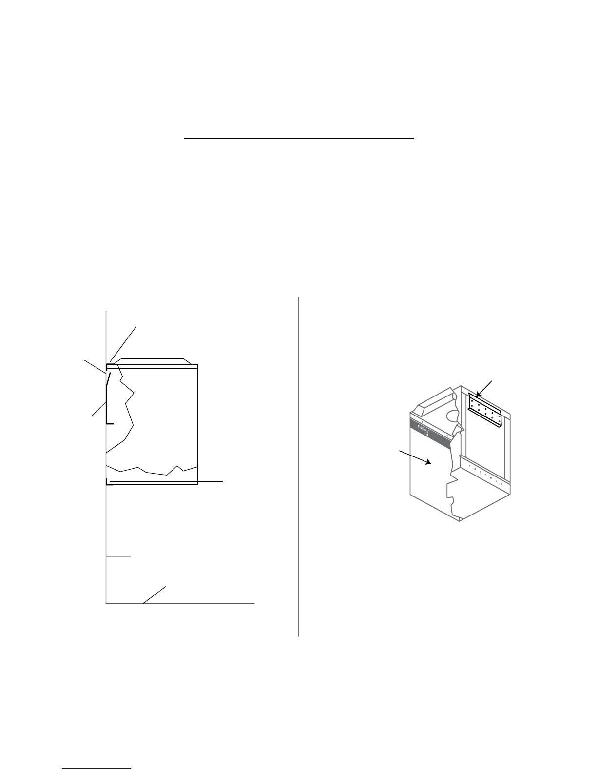
TO AN APPROVED SANITARY WASTE LINE
This installation should only be done in accordance with all applicable local plumbing codes and regulations.
The unit’s 1-1/4 inch (31.75 mm) O.D. drain tailpiece is designed for connection with standard compression
type plumbing ttings. There is room inside of the stainless steel housing for the use of a standard “P” type
plumbing connection. The waste outlet should be located in the wall behind the unit. The UTILITIES
LOCATION DIAGRAM (page 8) shows the appropriate location for the waste duct.
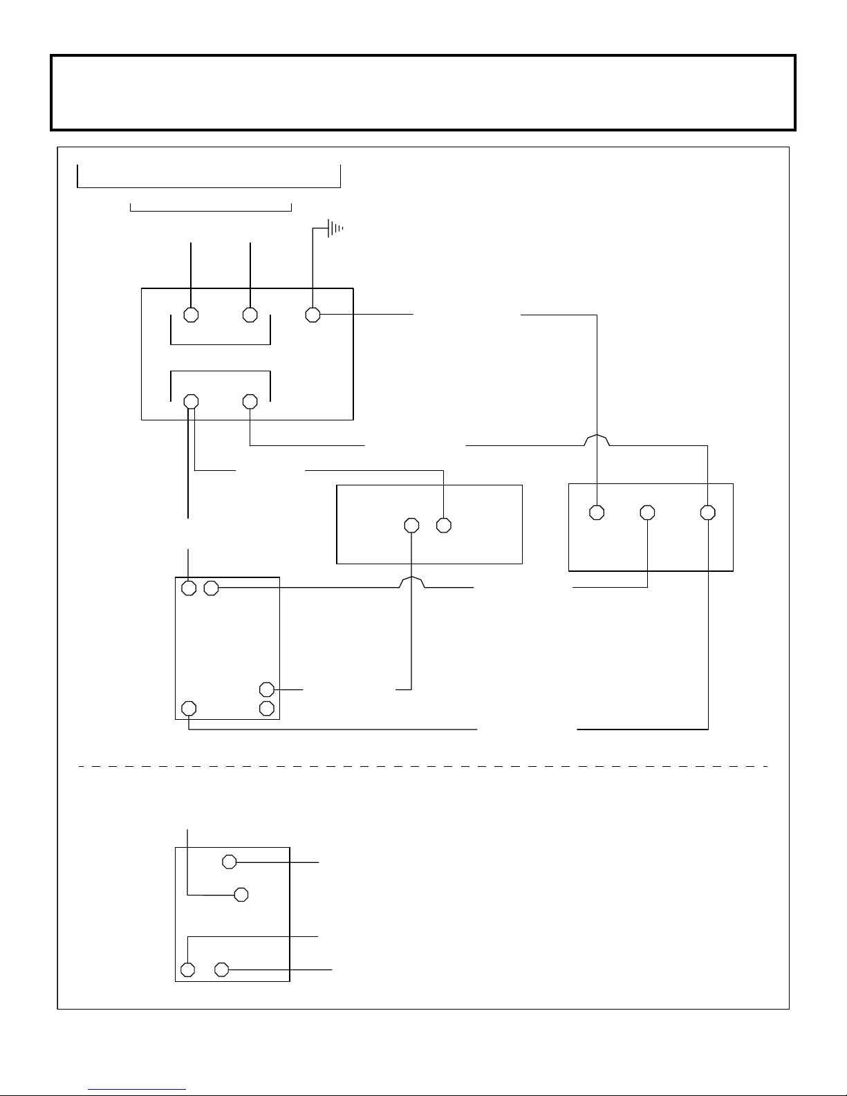
PROPER ELECTRICAL CONNECTIONS FOR THE SUITMATE®UNIT
Note: Strictly follow all applicable local electrical codes and regulations.
The SUITMATE®unit is equipped with a ground fault circuit interrupter (GFCI), that is designed to be
connected to a 115-V 20-Amp 60-Hz dedicated circuit that is protected by a fuse or circuit breaker of the
correct (20 Amp Maximum) size. A PLUG-IN INSTALLATION IS NOT ACCEPTABLE! The utilized circuit must
be run to the SUITMATE®unit’s weatherproof Junction Box that contains the GFCI. A liquid tight raceway/
exible conduit should be used from the circuit connection to the GFCI Junction Box. The UTILITIES
LOCATION DIAGRAM (page 8) shows the location of the suggested area behind the unit for the entrance of
the electrical raceway/exible conduit that does not interfere with the drainage connection.
Remove the cover of the weatherproof Junction Box, which contains the GFCI, and remove the GFCI
mounting screws. The circuit ground conductor must be connected to the green grounding screw located on
the GFCI. If no ground is available on the circuit utilized, you must provide a proper ground for the SUITMATE®
unit. The hot and neutral leads of the power circuit should be connected to the GFCI screw terminals marked
“LINE”. Connect the hot lead to the terminal marked “HOT WIRE” and the neutral lead to the terminal marked
“WHITE WIRE”. After the correct electrical connections have been properly made, remount the GFCI using
the screws previously removed. Reinstall the weatherproof Junction Box cover previously removed. This cover
provides access to the GFCI “TEST” and “RESET” buttons.
WARNING!
Do not route the raceway/conduit where wastewater can ow or drip on it.

©2017 Extractor Corporation
115-V 20-Amp 60-Hz SUITMATE
®
Unit
4
CUSTOMER'S ELECTRICAL SERVICE
115-V / 20-Amp / 60-HZ
BLACK AEC1842
(From Timer To Motor)
GREEN
SCREW
GFCI IS
"GROUND FAULT CIRCUIT INTERRUPTER"
MOTOR CONTROLLER AND SWITCH
BLACK
AEC1840
WHITE AEC1841
(From Timer To Motor)
TIMER
HOT NEU GROUND
GREEN
SCREW
HOT WHITE
HOT NEU
LOAD
BLACK
AEC1815
GFCI
WHITE AEC1813
(From GFCI To Motor)
BLACK AEC1843
(From Timer To Micro Switch)
MICRO SWITCH
OPEN
GREEN or GREEN/YELLOW AEC2061
(From GFCI To Motor)
RESET BUTTON, ON
TEST BUTTON, OFF
COMMON
MOTOR
SUITMATE®UNIT
L1 L2
22
2
1
34
BLACK AEC1842
(To Motor L1)
BLACK AEC1843
BLACK AEC1840
(To GFCI Load/Hot)
WHITE AEC1841
(To Motor L2)
COM
N.O.
TIMER
(To Micro Switch Common)
3
2
ALTERNATE TIMER OPTION
SUITMATE
®
WIRING DIAGRAM
115-V 20-Amp 60-Hz Self-Timed Unit

©2017 Extractor Corporation
115-V 20-Amp 60-Hz SUITMATE
®
Unit
5
TESTING AND OPERATION
After the mounting and all connections are complete, test the SUITMATE®unit as follows:
1) Make certain all packaging material is removed from the unit including material around the Motor.
2) Check to see that the Basket is empty and that the Lid moves freely.
3) Press down on the Lid. The unit will start and run for 8 seconds. While the unit is running it should run
smoothly and there should be no excessive vibration or noise.
4) Releasing the lid prior to the completion of the 8 second cycle causes the Basket to stop within one
(1) second.
5) Test the SUITMATE®unit by putting a wet swimsuit in the unit according to the instructions on the underside
of the Lid. If there is excessive vibration or noise it is usually caused by the improper loading of the
swimsuit. Be certain that the swimsuit is pushed to the bottom of the Basket and that all material is at least
two inches below the top of the Basket.
INSTALLATION TROUBLESHOOTING
If the SUITMATE®unit does not operate, check the following:
1) Check to see if there is power going to the unit. Check the circuit using an A.C. voltmeter set to the
appropriate range; measure across the “LINE” side of the GFCI.
2) Ensure that the GFCI switch is in the “ON” position. The “RESET” button should be depressed and a small
green light should be illuminated.
3) Check to see if there is power from the unit. Check the unit using an A.C. voltmeter to measure across the
“LOAD” side of the GFCI.
4) Check the TROUBLESHOOTING GUIDE (page 11) in this manual for additional troubleshooting assistance.
FINISHING THE INSTALLATION
Be certain to save this SUITMATE®UNIT MANUAL for future reference. If you have any concerns about the
correct installation of the SUITMATE®unit, please contact Extractor Corporation at: (Telephone) 800-553-3353,
POSTING THE WALL SIGN
Locate the top edge of the sign 60+/- 1/16” (152.5cm +/- 2mm) above the oor centered over the SUITMATE®
unit. At this height the sign will not be blocked when the lid is raised. It will also serve as a stop to keep the Lid
from striking the wall behind the unit.
The sign has an adhesive foam backing. Be certain the surface that the sign is to be mounted to is clean and
dry. Without touching the sign to the wall, align the top of the sign 60+/- 1/16” (152.5cm +/- 2mm) above the
oor and at the center of the unit. Press the sign to the wall and rub rmly over the adhesive portion of the sign.
Other manuals for SUITMATE
3
Table of contents
Other Extractor Corporation Scrubber manuals