Extron electronics MVC 121 Plus User manual
User Guide
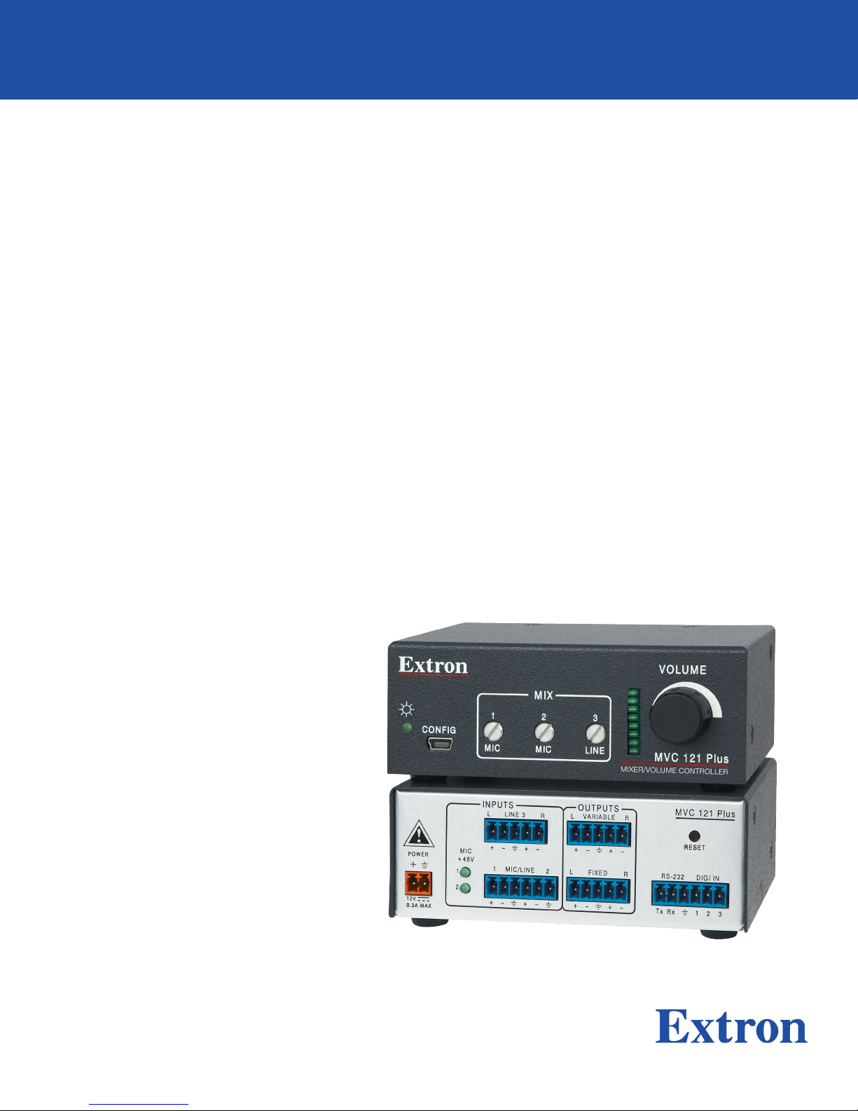
MVC 121 Plus
Audio Products:
Mixers and Processors
Three Input Stereo Mixer with DSP
68-1937-01 Rev. C
01 19
Safety Instructions
Safety Instructions • English
WARNING: This symbol, ,when used on the product, is
intended to alert the user of the presence of uninsulated dangerous
voltage within the product’s enclosure that may present a risk of electric
shock.
ATTENTION: This symbol, , when used on the product, is intended
to alert the user of important operating and maintenance (servicing)
instructions in the literature provided with the equipment.
For information on safety guidelines, regulatory compliances, EMI/EMF
compatibility, accessibility, and related topics, see the Extron Safety and
Regulatory Compliance Guide, part number 68-290-01, on the Extron
website, www.extron.com.
Sicherheitsanweisungen • Deutsch
WARNUNG: Dieses Symbol auf dem Produkt soll den Benutzer
darauf aufmerksam machen, dass im Inneren des Gehäuses dieses
Produktes gefährliche Spannungen herrschen, die nicht isoliert sind und
die einen elektrischen Schlag verursachen können.
VORSICHT: Dieses Symbol auf dem Produkt soll dem Benutzer in
der im Lieferumfang enthaltenen Dokumentation besonders wichtige
Hinweise zur Bedienung und Wartung (Instandhaltung) geben.
Weitere Informationen über die Sicherheitsrichtlinien, Produkthandhabung,
EMI/EMF-Kompatibilität, Zugänglichkeit und verwandte Themen finden Sie in
den Extron-Richtlinien für Sicherheit und Handhabung (Artikelnummer
68-290-01) auf der Extron-Website, www.extron.com.
Instrucciones de seguridad • Español
ADVERTENCIA: Este símbolo, , cuando se utiliza en el producto,
avisa al usuario de la presencia de voltaje peligroso sin aislar dentro del
producto, lo que puede representar un riesgo de descarga eléctrica.
ATENCIÓN: Este símbolo, , cuando se utiliza en el producto, avisa
al usuario de la presencia de importantes instrucciones de uso y
mantenimiento recogidas en la documentación proporcionada con el
equipo.
Para obtener información sobre directrices de seguridad, cumplimiento
de normativas, compatibilidad electromagnética, accesibilidad y temas
relacionados, consulte la Guía de cumplimiento de normativas y seguridad
de Extron, referencia 68-290-01, en el sitio Web de Extron, www.extron.com.
Instructions de sécurité • Français
AVERTISSEMENT : Ce pictogramme, , lorsqu’il est utilisé sur le
produit, signale à l’utilisateur la présence à l’intérieur du boîtier du
produit d’une tension électrique dangereuse susceptible de provoquer
un choc électrique.
ATTENTION : Ce pictogramme, , lorsqu’il est utilisé sur le produit,
signale à l’utilisateur des instructions d’utilisation ou de maintenance
importantes qui se trouvent dans la documentation fournie avec le
matériel.
Pour en savoir plus sur les règles de sécurité, la conformité à la
réglementation, la compatibilité EMI/EMF, l’accessibilité, et autres sujets
connexes, lisez les informations de sécurité et de conformité Extron, réf.
68-290-01, sur le site Extron, www.extron.com.
Istruzioni di sicurezza • Italiano
AVVERTENZA: Il simbolo, , se usato sul prodotto, serve ad
avvertire l’utente della presenza di tensione non isolata pericolosa
all’interno del contenitore del prodotto che può costituire un rischio di
scosse elettriche.
ATTENTZIONE: Il simbolo, , se usato sul prodotto, serve ad
avvertire l’utente della presenza di importanti istruzioni di funzionamento
e manutenzione nella documentazione fornita con l’apparecchio.
Per informazioni su parametri di sicurezza, conformità alle normative,
compatibilità EMI/EMF, accessibilità e argomenti simili, fare riferimento
alla Guida alla conformità normativa e di sicurezza di Extron, cod. articolo
68-290-01, sul sito web di Extron, www.extron.com.
Instrukcje bezpieczeństwa • Polska
OSTRZEŻENIE: Ten symbol, , gdy używany na produkt, ma na celu
poinformować użytkownika o obecności izolowanego i niebezpiecznego
napięcia wewnątrz obudowy produktu, który może stanowić zagrożenie
porażenia prądem elektrycznym.
UWAGI: Ten symbol, , gdy używany na produkt, jest przeznaczony do
ostrzegania użytkownika ważne operacyjne oraz instrukcje konserwacji
(obsługi) w literaturze, wyposażone w sprzęt.
Informacji na temat wytycznych w sprawie bezpieczeństwa, regulacji
wzajemnej zgodności, zgodność EMI/EMF, dostępności i Tematy pokrewne,
zobacz Extron bezpieczeństwa i regulacyjnego zgodności przewodnik, część
numer 68-290-01, na stronie internetowej Extron, www.extron.com.
Инструкция по технике безопасности •Русский
ПРЕДУПРЕЖДЕНИЕ: Данны й символ, , е сл и указан
на пр одукте, пр едупр еждает пользо в ате ля о наличии
неизолир ованного опасного напр яжения внутр и
кор пуса пр одукта, котор ое может пр ивести к пор ажению
э л е кт р и ч е с ки м т о ко м .
ВНИМАНИЕ: Данны й символ, , если указан на пр одукте,
пр едупр еждает п о льзов ателя о н аличии в ажны х инстр укций
по эксплуатации и о б служив анию в р уко в о дств е,
пр илагаемом к данному об ор удованию.
Для получения инф ор мации о пр ав илах те хники б езо п асно сти,
соб людении нор мативны х тр еб ов аний , электр омагнитной
совместимости (Э М П/Э ДС ), возможности доступа и др угих
вопр осах см. р уководство по б езопасности и соб людению
нор матив ны х тр еб ов аний Extr on на сай те Extr on: ,
www.extron.com, но ме р по каталогу - 68 -2 9 0-01.
安全说明 •简体中文
警告:产品上的这个标志意在警告用户该产品机壳内有暴露的危险 电压,
有触电危险。
注意:产品上的这个标志意在提示用户设备随附的用户手册中有
重要的操作和维护(维修)说明。
关于我们产品的安全指南、遵循的规范、EMI/EMF 的兼容性、无障碍
使用的特性等相关内容,敬请访问 Extron 网站 , www.extron.com,参见
Extron 安全规范指南,产品编号 68-290-01。
안전 지침 • 한국어
경고: 이 기호 가 제품에 사용될 경우, 제품의 인클로저 내에 있는
접지되지 않은 위험한 전류로 인해 사용자가 감전될 위험이 있음을
경고합니다.
주의: 이 기호 가 제품에 사용될 경우, 장비와 함께 제공된 책자에 나와
있는 주요 운영 및 유지보수(정비) 지침을 경고합니다.
안전 가이드라인, 규제 준수, EMI/EMF 호환성, 접근성, 그리고 관련 항목에
대한 자세한 내용은 Extron 웹 사이트(www.extron.com)의 Extron 안전 및
규제 준수 안내서, 68-290-01 조항을 참조하십시오.
安全記事 • 繁體中文
警告:若產品上使用此符號,是為了提醒使用者,產品機殼內存在著
可能會導致觸電之風險的未絕緣危險電壓。
注意 若產品上使用此符號,是為了提醒使用者,設備隨附的用戶手冊中有
重 要 的 操 作 和 維 護( 維 修 )説 明 。
有關安全性指導方針、法規遵守、EMI/EMF 相容性、存取範圍和相關主題的詳細資
訊,請瀏覽 Extron 網站:www.extron.com,然後參閱《Extron 安全性與法規
遵守手冊》,準則編號 68-290-01。
安全上のご注意 • 日本語
警告: この記号 が製品上に表示されている場合は、筐体内に絶縁されて
いない高電圧が流れ、感電の危険があることを示しています。
注意:この記号 が製品上に表示されている場合は、本機の取扱説明書に
記載されている重要な操作と保守(整備)の指示についてユーザーの注意
を喚起するものです。
安全上のご注意、法規厳守、EMI/EMF適合性、その他の関連項目に
つ い て は 、エ ク スト ロ ン の ウェブ サ イト www.extron.com よ り 『 Extron Safety
and Regulatory Compliance Guide』 ( P/N 68-290-01) をご覧ください。
Copyright
© 2011-2018 Extron Electronics. All rights reserved. www.extron.com
Trademarks
All trademarks mentioned in this guide are the properties of their respective owners.
The following registered trademarks (®), registered service marks (SM), and trademarks (TM) are the property of RGBSystems, Inc. or
ExtronElectronics (see the current list of trademarks on the Terms of Use page at www.extron.com):
Registered Trademarks (®)
Extron, Cable Cubby, ControlScript, CrossPoint, DTP, eBUS, EDID Manager, EDID Minder, Flat Field, FlexOS, Glitch Free. Global
Configurator, GlobalScripter, GlobalViewer, Hideaway, HyperLane, IPIntercom, IPLink, KeyMinder, LinkLicense, LockIt, MediaLink,
MediaPort, NetPA, PlenumVault, PoleVault, PowerCage, PURE3, Quantum, Show Me, SoundField, SpeedMount, SpeedSwitch,
StudioStation, SystemINTEGRATOR, TeamWork, TouchLink, V-Lock, VideoLounge, VN-Matrix, VoiceLift, WallVault, WindoWall, XTP,
XTPSystems, and ZipClip
Registered Service Mark(SM): S3 Service Support Solutions
Trademarks (™)
AAP, AFL (Accu-RateFrameLock), ADSP(Advanced Digital Sync Processing), Auto-Image, AVEdge, CableCover, CDRS(ClassD
Ripple Suppression), Codec Connect, DDSP(Digital Display Sync Processing), DMI (DynamicMotionInterpolation), DriverConfigurator,
DSPConfigurator, DSVP(Digital Sync Validation Processing), eLink, EQIP, Everlast, FastBite, FOX, FOXBOX, IP Intercom HelpDesk,
MAAP, MicroDigital, Opti-Torque, PendantConnect, ProDSP, QS-FPC(QuickSwitch Front Panel Controller), RoomAgent, Scope-Trigger,
ShareLink, SIS, SimpleInstructionSet, Skew-Free, SpeedNav, Triple-Action Switching, True4K, Vector™ 4K , WebShare, XTRA, and
ZipCaddy

FCC Class A Notice
This equipment has been tested and found to comply with the limits for a Class A digital
device, pursuant to part15 of the FCC rules. The ClassA limits provide reasonable
protection against harmful interference when the equipment is operated in a commercial
environment. This equipment generates, uses, and can radiate radio frequency energy
and, if not installed and used in accordance with the instruction manual, may cause
harmful interference to radio communications. Operation of this equipment in a
residential area is likely to cause interference. This interference must be corrected at the
expense of the user.
NOTE: For more information on safety guidelines, regulatory compliances, EMI/
EMF compatibility, accessibility, and related topics, see the Extron Safety and
Regulatory Compliance Guide on the Extron website.
VCCI-A Notice
この装置は、クラスA情報技術装置です。 この装置を家庭環境で使用すると、電波妨害を引き
起こすことがあります。 その場合には使用者が適切な対策を講ずるよう要求されることがあります。
VCCI-A
Conventions Used in this Guide
Notifications
The following notifications are used in this guide:
ATTENTION:
• Risk of property damage.
• Risque de dommages matériels.
NOTE: A note draws attention to important information.
Software Commands
Commands are written in the fonts shown here:
^AR Merge Scene,,0p1 scene 1,1 ^B 51 ^W^C.0
[01] R 0004 00300 00400 00800 00600 [02] 35 [17] [03]
EX! *X1&*X2)*X2#*X2! CE}
NOTE: For commands and examples of computer or device responses used in
this guide, the character “0” is used for the number zero and “O” is the capital
letter “o.”
Computer responses and directory paths that do not have variables are written in the
font shown here:
Reply from 208.132.180.48: bytes=32 times=2ms TTL=32
C:\Program Files\Extron
Variables are written in slanted form as shown here:
ping xxx.xxx.xxx.xxx —t
SOH R Data STX Command ETB ETX
Selectable items, such as menu names, menu options, buttons, tabs, and field names
are written in the font shown here:
From the File menu, select New.
Click the OK button.
Specifications Availability
Product specifications are available on the Extron website, www.extron.com.
Extron Glossary of Terms
A glossary of terms is available at http://www.extron.com/technology/glossary.aspx.


Contents
Introduction ...............................................1
About This Guide................................................. 1
MVC121Plus Description................................... 1
MVC121Plus Features....................................... 1
MVC121Plus Application Diagram ..................... 2
Installation.................................................3
Rear Panel Features ............................................ 3
Front Panel Features............................................ 7
Operation.................................................10
MVC121Plus Operation ................................... 10
Front Panel Operation........................................ 11
Rear Panel Operation ........................................ 11
Power Cycle...................................................... 12
Firmware Updates ............................................. 12
Reset Actuator and LED .................................... 12
Digital Input Port................................................ 13
DSP Processing and Signal Flow....................... 15
Mic/Line Input Signal Chain ............................... 16
Filter Processor Block........................................ 17
Filter .................................................................. 18
Mixer ................................................................. 22
Output Channels ............................................... 26
Volume .......................................................... 26
Gain .............................................................. 27
SIS Programming and Control .................28
Connection Options........................................... 28
USB Port Details:........................................... 28
MVC121Plus-initiated Messages ................. 29
Using the Command/Response Tables .......... 29
Error Responses............................................ 30
Command/Response Table for Basic SIS
Commands ...................................................... 31
Symbol Definitions ......................................... 31
Command/Response Table for Basic
MVC121Plus SIS Commands..................... 32
Command/Response Tables for DSP SIS
Commands ...................................................... 35
OID................................................................ 35
Error Responses............................................ 36
Symbol Definitions ......................................... 36
Command/Response Table for
MVC121Plus DSP SIS Commands............. 37
Software Control......................................39
Software Control................................................ 39
Windows-based Program Control...................... 39
Installing the DSP Configurator Program........ 40
Install the USB Driver..................................... 41
DSP Configurator Program................................ 42
Using the Program......................................... 43
Help .............................................................. 43
Emulate Mode vs. Live Mode......................... 44
Synchronizing: Pull vs. Push .......................... 44
Selecting Live Mode and Pushing or
Pulling a Configuration.................................. 45
Reference ................................................48
Mounting........................................................... 48
Tabletop Use ................................................. 48
UL Rack Mounting Guidelines........................ 48
Rack Mounting .............................................. 49
Furniture Mounting......................................... 49
Firmware Loader ............................................... 50
MVC121Plus Hardware Reset Modes.............. 51
viiMVS 121 Plus • Contents

MVS 121 Plus • Contents viii

MVC 121 Plus • Introduction 1
Introduction
This section describes this manual and the MVC121Plus, including:
• About This Guide • MVC121Plus Features
• MVC121Plus Description • MVC121Plus Application Diagram
About This Guide
This guide contains information about the Extron MVC121Plus audio mixer and volume
controller with DSP. Unless otherwise specified, references in this guide to the “mixer” or
“MVC” relate to the features or operation of the MVC121Plus.
MVC121Plus Description
The MVC121Plus is an audio mixer and volume controller that will mix up to two
mic/line inputs (mono, balanced or unbalanced) with one line level input (stereo, balanced,
or unbalanced). All audio input signals are converted from analog to digital prior to
processing or routing. Each mic input and the stereo line level input have their own gain
control adjustment screws, and the mixed output also features a volume control knob.
The MVC offers gain, Parametric EQ filter, and tone processing with quick and intuitive
configuration using the DSP Configurator software. The DSP built into the MVC provides
wide dynamic range and utilizes 24-bit audio converters with 48 kHz sampling to maintain
audio signal transparency.
Two sets of outputs include a fixed output that is independent from volume control, and
a variable output that is volume adjustable. All inputs and outputs are via 3.5 mm captive
screw connectors, and the gain/volume settings are indicated by an eight segment LED
ladder.
Rotating the gain adjustment screw clockwise increases gain, rotating the screw
counterclockwise decreases gain. Gain values adjust in 1dB increments.
Volume adjustment interval varies with knob rotation, that is, turning the knob clockwise
increases the volume and turning the knob counterclockwise decreases the volume. The
volume is increased more rapidly at lower volume settings.
The MVC offers RS-232 control of input gain/attenuation, and control of output volume. The
latest firmware can be uploaded using RS-232 or USB and the Extron Firmware Loader
program for Windows®.
MVC121Plus Features
Emulate and live modes for configuration — The DSP Configurator control program can
be used in emulate mode to create an MVC121Plus configuration offline. The modifications
can be saved and applied to the unit when a connection is established. In live mode, the
changes are made directly to the unit.
Two mic/line inputs and one line level input — Two mic/line (mono, balanced or
unbalanced) inputs can mix with one line level (stereo, balanced or unbalanced) input.
MVC 121 Plus • Introduction 2
Fixed and variable outputs — The MVC includes a fixed output and a volume adjustable
variable output.
Multi-function LED level indicator — Automatically displays the mix-point gain or output
volume setting for the front panel controls, and also functions as an output level meter.
Fixed, low latency DSP processing — Input to output latency within the MVC121Plus
is fixed regardless of the number of active channels or processes. Fixed, low latency
processing keeps audio in sync with video, and prevents distractions to the presenter
resulting from delayed live audio.
48-volt phantom power for condenser microphones — 48 VDC phantom power is
available for mic inputs 1 and 2.
Soft limits provide optimal adjustment range — The volume range for the variable
output and the gain range for the three mix points can be limited using the soft limits to
maintain optimal minimum and maximum levels when using external control. This prevents
operators from over or under-adjusting levels when using digital I/O or RS-232 control. The
DSP Configurator software provides quick drag-and-drop adjustment of soft limits.
SpeedNav™ keyboard navigation — SpeedNav enables user-friendly, keyboard-based
navigation of the DSP Configurator software without the need for a mouse or touchpad.
Using keyboard navigation keys and shortcuts, the user can access any input or output,
mix-points, and all audio DSP tools. Using only the keyboard for software access can help
expedite audio system setup and commissioning.
Rear panel RS-232 control port —The MVC121Plus can be configured using Extron
Simple Instruction Set (SIS™) commands from a PC using an RS-232 cable.
Front panel USB control port —The MVC121Plus can be configured by Extron Simple
Instruction Set (SIS) commands from a PC using a USB cable.
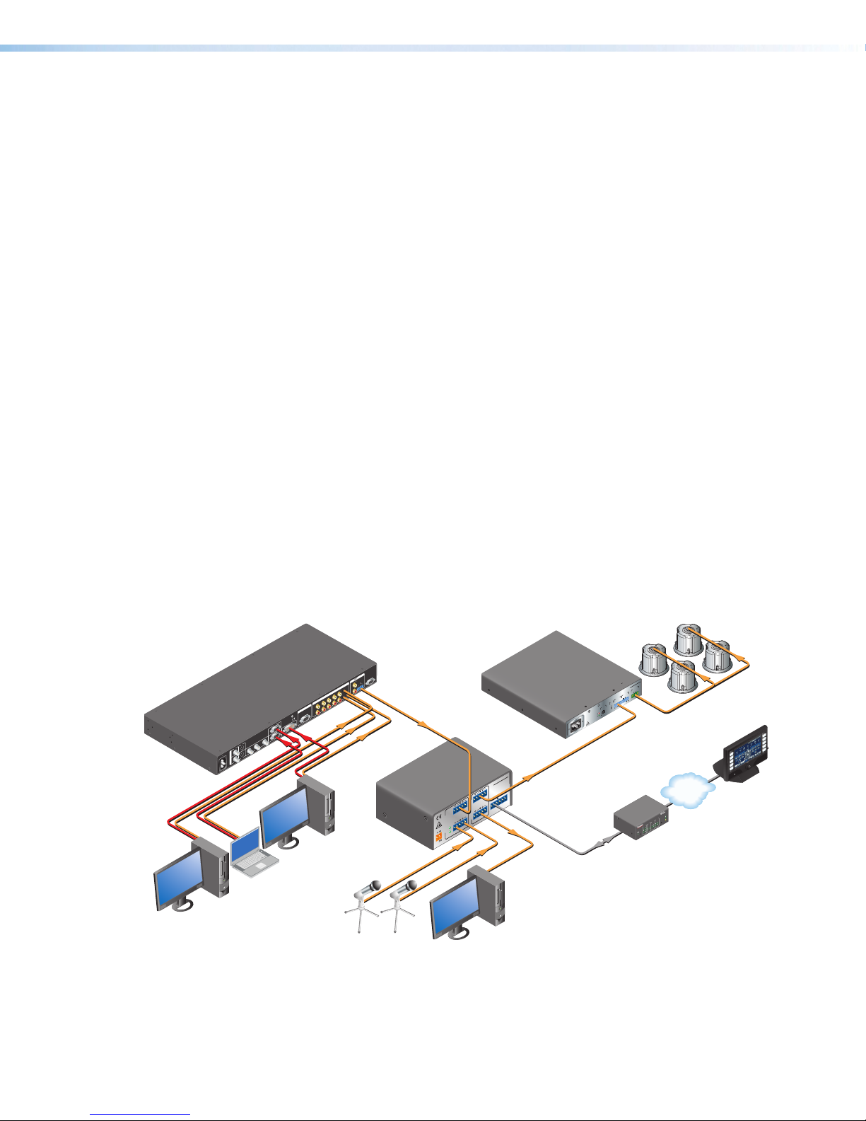
MVC121Plus Application Diagram
100-240V 50-60Hz
I
N
P
U
T
VID
VID
YC
YB-Y R-Y RGB DVI 8
1
245
3
L
2
134 5 6
7
R
AUDIO INPUT
L
A
BRS-232
R
OUTPUT
LR
OUTPUT
RGB
Y,B-Y, R-Y
8
7
RGB
6
LISTED
1T23
I.T.E.
CUS
CLASS 2 WIRING
STANDBY
L
(MONO)
R
LISTED
C US
70V
OUTPUT
VOL/MUTE
50mA10V
REMOTE
INPUTS
LIMITER/
PROTECT
SIGNAL
LEVEL
0
HPF
OFF
80Hz
XPA 2001-70V
17TT
AUDIO/VIDEO
APPARATUS
100-240V 1.3A,50-60Hz
2
1
+48V
MIC
I
N
P
U
T
S
1 2MIC/LINE
LINE 3
O
U
T
P
U
T
S
LRR
L
POWER
0.3A MAX
12V RS-232
21
Tx Rx
VARIABLE
FIXEDL R
DIGI IN
3
MIXER/VOLUME
CONTROLLER
MVC 121 Plus
13
1
4
2
3
1
4
2
3
1
4
2
2
3
100
LINK
ACT
COM IR INPUT RELAY
TX RX
R
IPL250
®
ON
OFF
DISPLAY
MUTE
SCREEN
UP
SCREEN
DOWN
VCR
DVD
DOC
CAM
LAPTOP
PC
Extron
IN1508
Scaling Presentation
Switcher
Laptop
Desk Microphone
PC
PC Podcasting/
Recording Station
PC
TCP/IP TouchLink™
Control
System
Extron
SI 26CT
Two-way Ceiling
Speakers
Extron
XPA 2001-70V
Power
Amplier
Extron
MVC 121 Plus
Three Input Stereo
Mixer with DSP
Figure 1. MVC121Plus Application Diagram
1

MVC 121 Plus • Installation 3
Installation
This section describes the features and connectors for the MVC121Plus:
• Rear Panel Features •Front Panel Features
Rear Panel Features
2
1
+48V
MIC
12MIC/LINE
LINE 3
LRRL
POWER
0.3A MAX
12V
RS-232
VARIABLE
FIXEDLR DIGI IN
MVC 121 Plus
Tx Rx 1 2 3
INPUTS OUTPUTS
RESET
1122336
67
788
4
45
59
9
Figure 2. MVC121Plus Rear Panel
1POWER connector — Connect the two pole, 3.5 mm captive screw connector from
the 12 VDC external power supply (provided) to this socket on the rear panel. Ensure
the connections have the correct polarity as shown in the illustration below:
DC Power
Input
POWER
12V
0.4A MA
X
Power Supply
Output Cord
SECTION A–
A
RidgesSmooth
AA
DC Power Cord
Captive Screw Connector
Ground
+12 VDC input
G
External Power Supply
(12 VDC, 0.5 A max.)
Ground all
Devices
Figure 3. Power Supply Connection
ATTENTION:
• Always use a power supply supplied or specified by Extron. Use of an
unauthorized power supply voids all regulatory compliance certification and
may cause damage to the supply and the end product.
• Utilisez toujours une source d’alimentation fournie ou recommandée par
Extron. L’utilisation d’une source d’alimentation non autorisée annule toute
certification de conformité réglementaire, et peut endommager la source
d’alimentation et l’unité.
2
3

MVC 121 Plus • Installation 4
ATTENTION:
• Unless otherwise stated, the AC/DC adapters are not suitable for use in air
handling spaces or in wall cavities. The power supply is to be located within the
same vicinity as the Extron AV processing equipment in an ordinary location,
Pollution Degree 2, secured to the equipment rack within the dedicated closet,
podium or desk. Power over Ethernet (PoE) is intended for indoors use only. No
part of the network that uses PoE can be routed outdoors.
• Sauf mention contraire, les adaptateurs CA/CC ne conviennent pas à une
utilisation dans les espaces d’aération ou dans les cavités murales. La source
d’alimentation doit être placée à proximité de l’équipement Extron dans
un emplacement ordinaire soumis à un degré de pollution de catégorie II,
solidement fixé au rack d’équipement d’une baie technique, d’un pupitre, ou
d’un bureau. L’alimentation via Ethernet (PoE) est destinée à une utilisation en
intérieur uniquement. Elle doit être connectée seulement à des réseaux ou des
circuits qui ne sont pas routés au réseau ou au bâtiment extérieur.
• The installation must always be in accordance with the applicable provisions of
National Electrical Code ANSI/NFPA 70, article 725 and the Canadian Electrical
Code part 1, section 16. The power supply shall not be permanently fixed to
building structure or similar structure.
• Cette installation doit toujours être conforme aux dispositions applicables
du Code américain de l’électricité (National Electrical Code) ANSI/NFPA 70,
article 725, et du Code canadien de l’électricité, partie1, section16. La source
d’alimentation ne devra pas être fixée de façon permanente à la structure de
bâtiment ou à d’autres structures similaires.
NOTE: The length of the exposed wires in the stripping process is critical. The
ideal length is 3/16 inches (5 mm). Any longer and the exposed wires may touch,
causing a short circuit between them. Any shorter and the wires can be easily
pulled out even if tightly fastened by the captive screws.
Do not tin the wires. Tinned wire does not hold its shape and can become loose
over time.
2MIC 1 and 2 +48 V phantom power LED indicators — The LED lights whenever the
corresponding mic phantom power is on and goes off when the phantom power is off.
3MIC/LINE inputs 1 and 2 — Up to two mono microphones or line level signals,
balanced and/or unbalanced, may be connected to the 6-pole 3.5 mm captive screw
connector. Inputs provide gain settings to accommodate consumer and pro operating
line level sources, with sufficient gain to support mic level audio.
12MIC/LINE
Balanced MIC Unbalanced MI
C
Jumper
NOTE: Mic inputs will be evenly
mixed into both left and right
outputs.
Figure 4. MIC/LINE Inputs
4
MVC 121 Plus • Installation 5
4Line input 3, left (L) and right (R) — A line level audio source, such as a CD player,
output from a switcher, DVD player, or other audio device, may be connected to
the 5-pole 3.5 mm captive screw connector. Line inputs provide gain settings to
accommodate consumer and pro operating line level sources. Balanced or unbalanced
stereo connections can be wired to this connector (see the following example diagram).
DVDCSR 6 RCA Adapter
MAIN 3
LR
MVC 121 MAIN wiring.eps
NOTE: Input devices cabled with two RCA male outputs may be connected to the
5-pole 3.5 mm captive screw connector using the Extron CSR 6 adapter.
Figure 5. Input Devices Cabled with Two RCA Male Outputs
To wire the captive screw connectors to the RCA or 3.5 mm mini phone plugs, see the
following illustrations.
Tip (+)
Sleeve ( )
Sleeve (Gnd )
Audio RCA connector color.eps
Right Channel
(Red Jacket)
Left Channel
(White Jacket)
Tip (Signal)
Sleeve ( )
Ring (R)
Tip (L)
3.5 mm TRS Connector
LR
LR
Unbalanced audioBalanced audio
Do not tin the wires!
Ring
Slee
ves
Tip
Sleeve
Tip
Sleeve
Tip
Tip
Ring
Figure 6. Wiring Captive Screw Connectors
5Variable output left (L) and right (R) — The balanced/unbalanced stereo output
to an amplifier from the 5-pole 3.5 mm captive screw connector is controlled by the
large main volume control knob on the front panel (see Front Panel Features on
page7). Volume range is from 0 to 100%, or -100 to 0dB.
Adjust the speaker volume by using the following sequence:
1. Adjust the volume of the amplifier down to its minimum setting.
2. Adjust the main volume knob of the MVC to its default level of 100% volume, or
0dB.
3. Adjust the volume of the amplifier to the desired level.
4. Make subsequent volume level adjustments by using the volume knob of the MVC.
NOTE: Output devices cabled with two RCA male outputs may be connected to the
5-pole 3.5 mm captive screw connector using the Extron CSR 6 adapter.
5
6
MVC 121 Plus • Installation 6
Sound System
CSR 6 RCA Adapter
VARIABLE
LR
Unbalanced Stereo Output
Tip
NO GROUND HERE.
Sleeve(s)
Tip
NO GROUND HERE.
Balanced Stereo Output
Tip
Ring
Sleeve(s)
Tip
Ring
LR
LR
Left
Right
Left
Right
CAUTION
For unbalanced audio, connect the sleeve(s)
to the center contact ground. DO NOT connect
the sleeve(s) to the negative (-) contacts.
ATTENTION:
• Connect the sleeve to ground. Connecting the sleeve to a negative (–) terminal
will damage the audio output circuits.
• Connectez le manchon à la borne de terre (Gnd). Connecter le manchon à une
borne négative(-) endommagera les circuits de la sortie audio.
Figure 7. Output Devices Cabled with Two RCA Male Outputs
6Fixed output left (L) and right (R) — The balanced/unbalanced stereo output from
the 5-pole 3.5 mm captive screw connector is output at a fixed volume adjustable gain
level for input to a recording device. Level can be adjusted at the recording device, or
using output gain control with a range of -24 to +12dB.
NOTE: The main volume control knob on the front panel operates independently of
the fixed output. Both the fixed and variable output connectors will output audio
simultaneously.
The fixed output connector is wired the same as the variable output connector. See 5,
variable output connector, for an example application diagram with cabling instructions
and a caution.
7RS-232 — Connect an RS-232 device (control system or PC) to the 6-pole 3.5 mm
captive screw connector for two-way RS-232 communication. Software for
RS-232 control is included with the MVC. See SIS Programming and Control (see
page28) for information on how to install and use the control software and SIS
commands.
Ground (Gnd,
)
Tx
RS-232
Receive (Rx)
Transmit (Tx)
Rx 123
DIGI IN
Figure 8. RS-232
8Digital input (DIGI IN) — A 6-pole 3.5 mm captive screw connector provides three
configurable ports designed to connect to various devices such as motion detectors,
alarms, buttons, photo (light) sensors, temperature sensors, or other devices. This
connector shares a common ground with the RS-232 connector (g). The wiring
diagram is shown below.
7
8
MVC 121 Plus • Installation 7
Do not tin the wires!
1
2
3
_
RS-232
21
Tx Rx
DIGI IN
3
Figure 9. Digital Input Wiring Diagram
Both the RS-232 and the digital input connectors may be used simultaneously by using
a 6-pin captive screw connector with two wires sharing the same ground connector
(see the diagram below).
RS-232 DIGI IN
Tx Rx 1 2 3
9Reset — The recessed reset button is used to access various modes of resets. The
green power LED on the front panel indicates what mode of reset was accessed (see
the MVC121Plus Hardware Reset Modes (see page51) section for additional
details).
Front Panel Features
VOLUME
CONFIG
MIX
MICMIC LINE
321
MIXER/VOLUME CONTROLLER
MVC 121 Plus
21 3 4 5 6 7
11223344556677
Figure 10. MVC121Plus Front Panel
1Power/Reset LED — Green power indicator lights when the MVC121Plus is
operational. The LED also blinks per mode reset (see Reset Actuator and LED on
page12).
2Configuration (Config) port — Connect a PC to the USB mini B-type connector for
configuring the MVC using the DSP Configurator software. The MVC121Plus USB
driver must be installed prior to using the port.
3Mic 1 gain control — Rotating the encoder screw clockwise increases the gain
setting, rotating the encoder screw counterclockwise decreases the gain. This
adjustment controls the single gain point in the mix matrix that mixes mono mic 1 levels
to the stereo output bus.
The gain adjustment is indicated by the LED indicator bar (6). When the encoder
screw rotation has stopped for three seconds or longer, the LED indicator returns to the
output meter indication.
9
10
MVC 121 Plus • Installation 8
4Mic 2 gain control (see figure10 on the previous page)— Rotating the encoder screw
clockwise increases the gain setting, rotating the encoder screw counterclockwise
decreases the gain setting. This adjustment controls the single gain point in the mix
matrix that mixes mono mic 2 levels to the stereo output bus.
The gain adjustment is indicated by the LED indicator bar (6). When the encoder
screw rotation has stopped for three seconds or longer, the LED indicator returns to the
output meter indication.
5Line level 3 gain control — Rotating the encoder screw clockwise increases the gain
setting, rotating the encoder screw counterclockwise decreases the gain setting. This
adjustment controls the single gain point in the mix matrix that mixes stereo line level
input 3 to the stereo output bus.
The gain adjustment is indicated by the LED indicator bar (f). When the encoder screw
rotation has stopped for three seconds or longer, the LED indicator returns to the output
meter indication.
6LED ladder indicator bar — As the mix-point gain or output volume increases or
decreases via the front panel controls, the LED indicator bar lights from the bottom to
the top to indicate the current mix-point or volume level, as shown in the table below.
As the volume is increased or decreased within a volume range, the top LED to be lit
flashes once. If the knob is turned past maximum volume, all 8 LEDs flash for as long as
the knob continues to be turned.
When the output volume is muted, the individual LEDs scroll from the top to the bottom
to indicate a muted state. The LEDs return to being a meter for the output signal when
the audio is unmuted. Unmute occurs when the mute process is reversed, or when an
encoder screw or the volume knob position is changed. All LEDs blink when the user
attempts to adjust the encoder position beyond the maximum gain level.
When no activity is detected for either the mix-point encoder screws or the volume
adjust knob, the LED indicator bar will reflect a combined L/R output meter level, where
the max level of either left or right meter is always displayed, as shown in the table
below.
NOTE: Mix-point or volume level is only displayed on the LED ladder indicator
whenever the front panel encoder screws or the volume adjustment knob are being
adjusted and not through DSP Configurator software or SIS commands.
LED Level Meter Display
(dB)
8 -6 to 0
7 -12 to -7
6 -18 to -13
5 -24 to -19
4 -30 to -25
3 -36 to -31
2 -42 to -37
1 -60 to -43
MVC 121 Plus • Installation 9
7Volume level adjust knob — Rotating the adjustment knob VOLUME
MIXER/VOLUME CONTROLLER
MVC 121 Plus
clockwise increases the output volume, rotating the knob
counterclockwise decreases the volume. The LEDs light from
bottom up as the volume level increases.
Use the rotary encoder to adjust the output volume from
0 (-100dB) to 100% (0dB). The default setting is 100% (0dB).
The knob step adjustments are as follows:
Volume
Range (dB)
Knob Step
Adjustment (dB)
-100 to -70 +/- 5dB
-70 to -30 +/- 3dB
-30 to -20 +/- 2dB
-20 to -0 +/- 1dB
The degree to which the volume is incremented or decremented for each step the
volume adjust knob is turned, depends on the current volume setting.
As the volume increases or decreases, the LED bar lights to indicate the current volume
range, as shown in the table below. As the volume is increased or decreased within a
volume range, the top LED to be lit flashes once. If the knob is turned past maximum
volume, all 8 LEDs flash, for as long as the knob continues to be turned.
In the table below, turning the volume adjust knob (7) affects the volume range and
turning the input gain control screws (3, 4, 5affects the mix-point range).
LED
Level
Volume Range
(dB)
Mix-point
Range (dB)
8 -4 to -0 +7 to +12
7 -9 to -5 +1 to +6
6 -14 to -10 -3 to +0
5 -19 to -15 -7 to -4
4 -29 to -20 -11 to -8
3 -49 to -30 -15 to -12
2 -69 to -50 -19 to -16
1 -99 to -70 -23 to -20

MVC 121 Plus • Operation 10
Operation
This section describes the operation of the MVC121Plus, including:
• MVC121Plus Operation •Mic/Line Input Signal Chain
• DSP Processing/Signal Flow •Mixer
• Filter Processor Block •Output Channels
MVC121Plus Operation
The MVC121Plus can be configured using a PC running Windows XP or better and the
DSPConfigurator software (available on the included disc or at www.extron.com), or the
Extron SISSimple Instruction Set using HyperTerminal or DataViewer.
The MVC121Plus is configured for immediate operation, with all inputs mixed to the
outputs. However, input gain must be set, especially for the microphone inputs, before the
device will function at optimal levels.
The front panel small rotary encoders control level at the mix-points, not at the input gain
stage. Mix-points have a gain range of −24dB to +12dB. In some instances, the mix-point
gain range may be too great, allowing for settings that are too loud or too soft, and in some
instances the loudest settings may cause feedback or clipping. Soft limits can be applied to
the mix-point gain ranges, limiting the gain range for smoother operation.
Mix-point levels and Variable output levels may be set using the front panel rotary controls.
Input gain should be set using the DSP Configurator software, which provides metering in
dBFS that will assist you in configuring the device for optimal operation. The MVC121Plus
is a digital device, therefore optimal operating levels are close to 0dBFS without ever going
over 0dBFS (0dB “full scale” on the input or output meters). Levels above 0dBFS cause
clipping, which is always audible on a digital device.
Soft limits may also be applied to the Variable output, which will prevent the volume from
becoming too loud or too soft. The Fixed output, while not affected by the front panel
Volume control, does include a gain stage that is configured with the DSP Configurator
software. The Fixed output gain setting can be used to optimize the level going to, for
example, a recording device or ALS system.
Lastly, the input signal chain provides a Filter/EQ block. Use these processors to optimize
the tonal quality of your source devices. A high-pass filter applied to a microphone will
reduce thumps and pops, while the parametric EQ can be used to give a talker more
presence, or to remove frequencies that are likely to cause feedback.
MVC 121 Plus • Operation 11
Front Panel Operation
VOLUME
CONFIG
MIX
MICMIC LINE
321
MIXER/VOLUME CONTROLLER
MVC 121 Plus
21 3 4 5 6 7
11223344556677
Figure 11. MVC121Plus Front Panel
1Power/Reset LED — Green power indicator lights solid when the MVC is operational.
The LED will blink when the reset button is pressed.
2Configuration connector — The USB 2.0 port uses a mini type-B connector to
connect to a host computer for control. The MVC121Plus USB driver must be installed
prior to using the port (see the Install the USB Driver on page41 for additional
information).
The MVC appears as a USB peripheral with bidirectional communication. The USB
connection can be used for software operation (see Windows-based Program
Control on page39), and SIS control (see Software Control on page39 for
additional information).
Rear Panel Operation
2
1
+48V
MIC
12MIC/LINE
LINE 3
LRRL
POWER
0.3A MAX
12V
RS-232
VARIABLE
FIXEDLR DIGI IN
MVC 121 Plus
Tx Rx 1 2 3
INPUTS OUTPUTS
RESET
1122336
67
788
4
45
59
9
Figure 12. MVC121Plus Rear Panel
1 2 3 4 5 6 7 8 —See Rear Panel Features starting on page3 section for
further details.
9Reset — The reset actuator initiates system resets (see Reset Actuator and LED on
page12 for additional information).
11
12

MVC 121 Plus • Operation 12
Power Cycle
Current mixing and audio processor settings, the current state of the device, are saved in
nonvolatile memory. When the unit is powered off, all settings are retained. When the unit
is powered back on, it recalls settings from the nonvolatile memory. If a configuration was
in process during the power down, these saved mix, audio level, and audio DSP processor
settings become active.
On power up the front power indicator LED lights solid when the unit is available for
operation or programming.
Firmware Updates
The firmware of the MVC121Plus can be updated through USB or RS-232 connection.
The user can obtain new firmware from the Extron website. After obtaining the new
firmware, upload it to the unit by launching Firmware Loader from the DSPConfigurator
program (see Software Control on page39), or using the Extron standalone Firmware
Loader software application available on the included disc or at www.extron.com.
Reset Actuator and LED
A recessed button on the rear panel initiates two reset modes. The green front panel LED
(figure11, 2on the previous page) blinks to indicate the reset modes as described in the
following section. See the previous front and rear panel diagrams.
Hardware Reset Modes:
With power on, when the reset button is held down the front and rear panel LEDs will pulse
(blink) every three seconds and put the unit in a different reset mode. The MVC121Plus will
default back to the base firmware that shipped with the unit from the factory allowing the
user to recover a unit that has incorrect code or updated firmware running.
NOTE: Control software may not function correctly if using an earlier firmware version.
MODE 1 —Firmware reset: Disconnect power to the MVC121Plus. Press and hold
the reset button while applying power to return the firmware to the version shipped with the
unit from the factory. This allows recovering a unit with incorrect or corrupt firmware.
All user files and settings are maintained.
MODE 5 —Factory default reset: With power on, press and hold the reset button until
the reset LED blinks 3 times (~9 seconds). Each flash will last for 0.25 seconds. Release
then momentarily (<1 second) press the reset button to return the MVC to factory default
conditions. If the second momentary press does not occur within 1 second, the reset is
exited.
The default (reset) state of the device is:
• Inputs 1 – 3 are mixed to fixed and variable outputs (set to 0dB gain).
• All outputs are active (unmuted, 100% volume or 0dB gain).
• DSP (Filter) is inactive.
• All audio inputs are active (0dB gain and unmuted).
Other manuals for MVC 121 Plus
3
Table of contents
Other Extron electronics Music Mixer manuals


