Extron electronics MIX 301 User manual
1
MIX 301 • User Guide
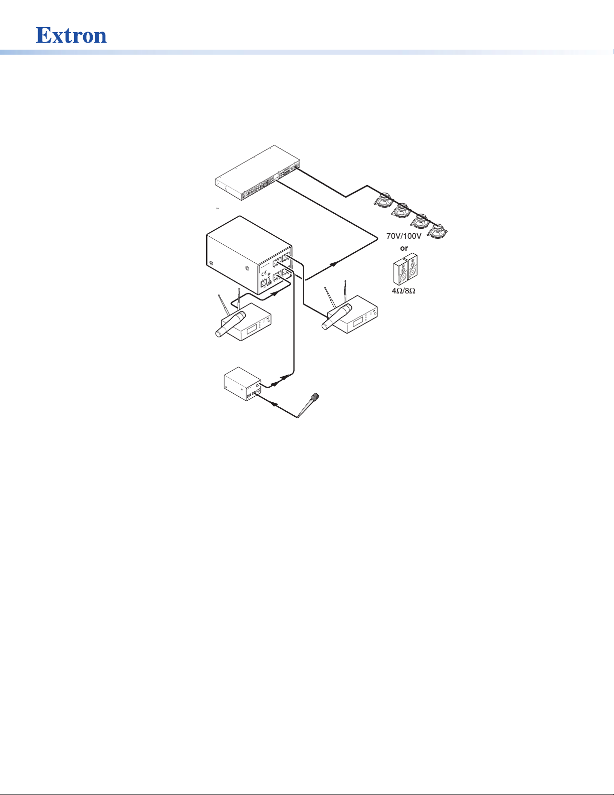
The MIX 301 is a three-input, one-output line level audio mixer. It accepts balanced or unbalanced input signals, and provides a
balanced or unbalanced output. The MIX 301 accommodates input sources with various impedances. Three recessed input gain
controls on the front panel enable adjustment of mix levels from -80 dB to +20 dB.
MIC to Line
Preamplifier
RS-232/MLC/IR
TxRxIR12V
ABC
PREAMP
100-240V
1.0AMAX.
50-60Hz
INPUT4
AUDIOINPUTS
LINELEVEL
MONO
AUDIO
AUDIO
LINEOUT
AUX/MIX
ADJUST
-42dB
TO
+24dB
L
R
L
R
L
R
123
INPUTS
OUTPUTS
VIDEO
HV
B
G
R
Y
123
INPUTS
MONITOROUT
45
6
C
DIRECT
XFMR
COM
4/8ohm
100V
70V
AMPLIFIEDOUTPUT
20WATTSMONO
Mono Amplified Output
Extron
MLS 406MA
MediaLink Switcher
Speakers
Wireless
Microphone System
AUX/MIX
Input
Wireless
Microphone System
Extr
on
MIX 301
3 Channel
Mix
er
MIX 301
3 CHANNEL
MIXER
IN 2 MIX OUT
IN 1 IN 3
12V
0.5a MAX
Microphone
12V
0.5a
POWER
MAX
MIC
INPUT REMOTE
VOL/MUTE
MLP101
MICTO LINE
PREAMPLIFIER
10V
MIC
OUTPUT
CH 003
CH 003
Figure 1. MIX 301 Application Diagram
Features
• Inputs — Captive screw connectors
• Outputs — Captive screw connectors
• Balanced and unbalanced signal compatibility
• Gain control for each channel — Wide adjustment range from -80 dB to +20 dB
• Compact size — Easy installation in a rack or in limited space
• Rack-mountable — 1U, one-eighth rack width metal enclosure
• External Extron Everlast™ power supply included
Mounting the MIX 301
The MIX 301 can be set on a table, mounted on a rack shelf, mounted on the back of the rack, mounted under a desk or table, or
installed on a projector mount (go to the Extron website for mounting options).
1
2
MIX 301 • User Guide (Continued)
UL Guidelines for Rack Mounting
The following Underwriters Laboratories (UL) guidelines pertain to the installation of the MIX 301 enclosure into a rack:
CAUTION: Risk of minor personal injury:
• Elevated operating ambient temperature — If the equipment is installed in a closed or multi-unit rack assembly, the
operating ambient temperature of the rack environment may be greater than room ambient. Therefore, consider installing the
equipment in an environment compatible with the maximum ambient temperature (Tma) specified by Extron.
• Reduced air flow — Install the equipment in the rack so that the amount of air flow required for safe operation of the
equipment is not compromised.
• Mechanical loading — Mount the equipment in the rack so that uneven mechanical loading does not create a hazardous
condition.
• Circuit overloading — When connecting the equipment to the supply circuit, consider the connection of the equipment
to the supply circuit and the effect that circuit overloading might have on overcurrent protection and supply wiring. Consider
equipment nameplate ratings when addressing this concern.
• Reliable earthing (grounding) — Maintain reliable grounding of rack-mounted equipment. Pay particular attention to supply
connections other than direct connections to the branch circuit (such as the use of power strips).
Consignes UL pour le montage en rack
Les consignes UL (« Underwriters Laboratories ») suivantes concernent l’installation en rack d’un boîtier MIX 301 :
ATTENTION : Risque de blessuremineure :
• Température ambiante élevée — En cas d’installation de l’équipement dans un rack fermé ou composé de
plusieurs unités, la température du rack peut être supérieure à la température ambiante. Par conséquent, il est
préférable d’installer l’équipement dans un environnement qui respecte la température ambiante maximale (Tma)
spécifiée par Extron.
• Réduction du flux d’air — Si l’équipement est installé dans un rack, veillez à ce que le flux d’air nécessaire pour
un fonctionnement sécurisé de l’équipement soit respecté.
• Charge mécanique — Installez l’équipement en rack de manière à éviter toute situation dangereuse causée par le
déséquilibre de la charge mécanique.
• Surcharge électrique — Lorsque vous connectez l’équipement au circuit d’alimentation, observez la connexion
de l’équipement et étudiez les effets possibles d’une surcharge du circuit sur les protections contre les surintensités
et les conducteurs d’alimentation. Consultez à cet égard les indications de la plaque d’identification de
l’équipement.
• Mise à la terre — Assurez-vous que l’équipement est correctement mis à la terre. Accordez une attention
particulière aux connexions électriques autres que les connexions directes au circuit de dérivation (ex. : les
multiprises).
Rear Panel Features and Cabling
MIX 301
3 CHANNEL
MIXER
IN 2MIX OUT
IN 1IN 3
12V
0.2 A MAX
2
2
24
4
46
6
6
5
5
5
3
3
3
1
1
1
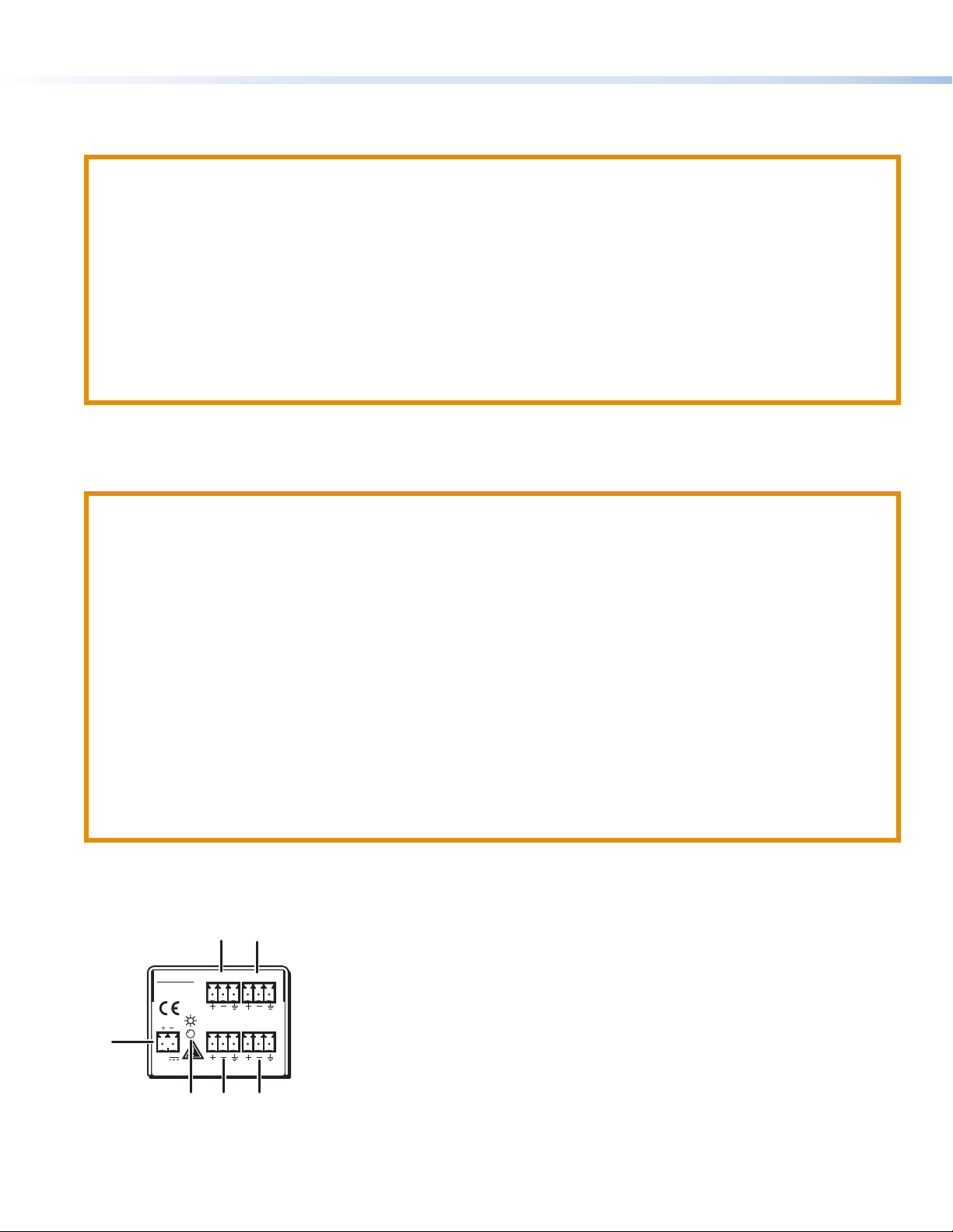
Figure 2. MIX 391 Rear Panel
1Captive screw power input connector
2Power LED
345 Balanced/unbalanced input connectors (IN 1, IN 2, IN 3)
6Balanced output connector (MIX OUT)
2
3
ATTENTION:
• Always use a power supply provided by or specified by Extron. Use of an unauthorized power supply voids all regulatory
compliance certification and may cause damage to the supply and the end product.
• When you are connecting the power supply, voltage polarity is extremely important. Applying power with incorrect
voltage polarity could damage the power supply and the interface. Identify the power cord negative lead by the ridges
on the side of the cord.
• The two power cord wires must be kept separate while the power supply is plugged in. Remove the power before wiring.
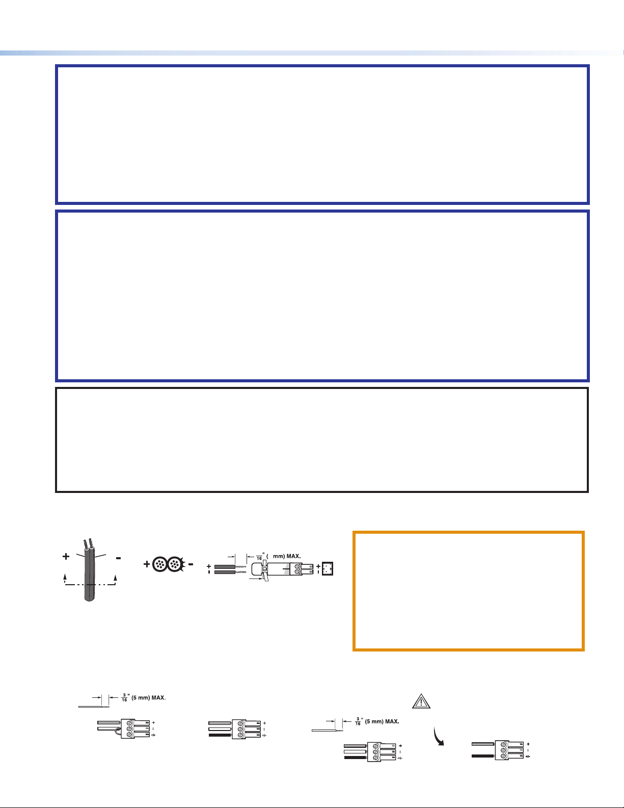
• The length of the exposed wires in the stripping process is important. The ideal length is 3/16 inches (5 mm).
• Do not tin the wire leads before installing into the connector. Tinned wires are not as secure in the connector and could
be pulled out. They may also break after being bent several times
AVERTISSEMENT :
• Utilisez toujours une source d’alimentation fournie ou recommandée par Extron. L’utilisation d’une source d’alimentation
non autorisée annule toute conformité réglementaire et peut endommager la source d’alimentation ainsi que le produit
final.
• Lorsque vous connectez la source d’alimentation, la polarité de la tension est extrêmement importante. Une alimentation
avec une polarité de tension incorrecte peut endommager la source d’alimentation ainsi que l’interface. Il est essentiel
d’identifier une connexion négative du cordon d’alimentation au niveau des stries sur les parties latérales du cordon.
• Les deux cordons d’alimentation doivent être maintenus à l’écart tant que la source d’alimentation est branchée.
Coupez l’alimentation avant de faire les raccordements.
• La longueur des câbles exposés est importante lorsque l’on entreprend de les dénuder. La longueur idéale est de 5mm
(3/16inches).
• Ne pas étamer les conducteurs avant de les insérer dans le connecteur. Les câbles étamés ne sont pas aussi bien fixés
dans le connecteur et pourraient être tirés. Ils peuvent aussi se casser après avoir été pliés plusieurs fois.
NOTES:
• To verify the polarity before connection, check the no load power supply output with a voltmeter.
• Your MIX 301 may have shipped with a blue captive screw connector. This blue connector can be plugged into either a
blue or an orange power receptacle. The blue connector does not have the extended tail or the included tie-wrap.
• After making any adjustments to the MIX 301, either via the front panel controls, SIS commands, or the Extron Audio
Products Control Program, wait at least 10 seconds after making those changes before disconnecting power to the
MIX 301. Failure to observe the 10-second timeout may result in those adjustments not being saved.
1Captive screw power input connector (see figure2 on the previous page) — Connect the included 12 VDC
external power supply into the 2-pole 3.5 mm captive screw connector. Be careful to observe the correct polarity.
Power Wiring.eps
Captive Screw
Connector
Tie Wrap
Power Supply
Output Cord
Ridges
Smooth
AA
SECTION A–A
5
3
2Power LED — Lights green to indicate that the MIX 301 has
power.
CAUTION: If not provided with a power supply,
this product is intended for use with a UL
Listed power source marked “Class 2” or
“LPS” rated 12 VDC, 0.5 A minimum.
ATTENTION : Si le produit n’est pas fourni avec
une source d’alimentation, il doit être utilisé
avec une source d’alimentation certifiée UL de
classe 2 ou LPS avec une tension nominale
de 12 Vcc, 0.5 A minimum.
345 Balanced/unbalanced input connectors (IN 1, IN 2, IN 3) — The balanced/unbalanced mono audio input
is wired to a 3-pole, 3.5 mm captive screw connector. Wire the connector as shown below on the left.
Tip
Sleeve
Ring
Tip
Sleeve
Unbalanced Input
Left or Right
Balanced Input
Unbalanced Output
Tip
Sleeve
NO GROUND HERE
Tip
Sleeve
Ring
Balanced Output
CAUTION
For unbalanced audio, connect the sleeve(s)
to the ground. DO NOT connect the sleeve to
the negative (-) contact.

68-1048-01 Rev. D
01 22
© 2005-2022 Extron Electronics — All rights reserved. www.extron.com
All trademarks mentioned are the property of their respective owners.
For information on safety guidelines, regulatory compliances, EMI/EMF compatibility, accessibility, and related topics, see the
Extron Safety and Regulatory Compliance Guide on the Extron website.
6Balanced output connector (MIX OUT) (see figure2 on page2) — The balanced mono output is wired to a
3-pole, 3.5 mm captive screw connector. Wire the connector on the right for balanced or unbalanced output devices
as shown on the previous page.
Front Panel Features
123
MTP SERIES
2
2
23
3
34
4
41
1
1
Figure 3. Front
Panel Features
1Power LED — Lights green to indicate that the MIX 301 has power.
234 Input channel audio gain controls — Adjusts the audio input gain for each input.
The gain is adjusted by rotating the screw and the adjustment range is from mute (fully
counterclockwise) to +20 dB (fully clockwise). See the note below.
NOTE: Unity gain (0 dB) for each input channel is around the 12 o’clock
123
(vertical) position with the potentiometer adjustment screws vertically
aligned with the indicator dots, as shown here:
The potentiometers of the MIX 301 are set precisely to unity gain at the factory. Once an
adjustment screw is turned, test equipment will be required to accurately reset the potentiometer
to unity gain.
FCC Class A Notice
This equipment has been tested and found to comply with the limits for a Class A digital device, pursuant to part15 of the FCC rules. The ClassA
limits provide reasonable protection against harmful interference when the equipment is operated in a commercial environment. This equipment
generates, uses, and can radiate radio frequency energy and, if not installed and used in accordance with the instruction manual, may cause
harmful interference to radio communications. Operation of this equipment in a residential area is likely to cause interference. This interference
must be corrected at the expense of the user.
Other manuals for MIX 301
1
Table of contents
Other Extron electronics Music Mixer manuals

Extron electronics
Extron electronics MVC 121 Plus Operator's manual

Extron electronics
Extron electronics MIX 301 User manual

Extron electronics
Extron electronics MVC 121 Plus User manual

Extron electronics
Extron electronics MVC 121 Plus User manual

Extron electronics
Extron electronics MVC 121 User manual


