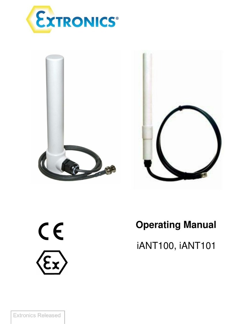
extronics iANT2 Series User manual

Operating Manual
3
Contents
1Introduction.......................................................................................................... 4
2Safety Information and Notes .............................................................................. 5
2.1 Storage of this Manual................................................................................... 5
2.2 List of Notes .................................................................................................. 5
2.3 Intended Purpose Usage............................................................................... 8
2.4 Transportation and Storage........................................................................... 8
2.5 Authorized Persons ....................................................................................... 8
2.6 Cleaning and Maintenance............................................................................ 8
2.7 Safety Precautions ........................................................................................ 9
2.8 Cleaning and Maintenance Intervals ............................................................. 9
2.9 Aggressive substances and environments .................................................... 9
2.10 Exposure to external stresses .................................................................... 9
3Mounting Details................................................................................................ 10
3.1 iANT212 ...................................................................................................... 10
3.2 iANT213 ...................................................................................................... 10
3.3 iANT214 ...................................................................................................... 11
3.4iANT215 ...................................................................................................... 12
3.5 iANT216 ...................................................................................................... 12
3.6 iANT217 ...................................................................................................... 13
3.8 iANT218 / iANT221 ...................................................................................... 14
3.7 iANT227 ...................................................................................................... 15

Operating Manual
4
1 Introduction
The iANT2xx range of rugged antennas provides a comprehensive selection of
antennas that can operate in the UHF, GSM, 2.4GHz or 5.8GHz WiFi frequency bands,
all of which are suitable for outdoor use at they have an IP rating of IP66 or higher, and
are protected against UV damage and corrosion in offshore environments.
Please Note: The iANT2xx range of antennas is classed as “Simple Apparatus” under
international intrinsic safety standards. IEC 60079-25 requires that simple apparatus
equipment used in an intrinsically safe electrical system is compliant with IEC 60079-
0, IEC 60079-11, IEC 60079-14 & IEC 60079-25. Extronics has assessed the iANT2xx
antenna range together with our intrinsically safe certified wireless products to provide
solutions compliant to all relevant standards. Therefore iANT2xx antennas can be
deployed in a hazardous area, as part of an Extronics system, without the need to
undergo further assessment. Compliance is also maintained if an iANT2xx antenna is
used with the Extronics iSOLATE501 RF galvanic isolator. If the antenna is not to be
used with Extronics’ products, then the system designer must assess the hazard and
demonstrate compliance to the relevant standards.

Operating Manual
5
2 Safety Information and Notes
2.1 Storage of this Manual
Keep this user manual safe and in the vicinity of the device. All persons who have to work on
or with the device should be advised on where the manual is stored.
2.2 List of Notes
The notes supplied in this chapter provide information on the following.
•Danger / Warning.
oPossible hazard to life or health.
•Caution
oPossible damage to property.
•Important
oPossible damage to enclosure, device or associated equipment.
•Information
oNotes on the optimum use of the device
Warning The iANT2xx series are classified as simple apparatus when used with an
Extronics iSOLATE501 galvanic isolator. Do not use an iANT2xx antenna
without first contacting Extronics for guidance and recommendations for
the use of the iANT2xx with specific hardware.
Important Installation of this equipment shall be carried out by suitably trained
personnel in accordance with the applicable code of practice (IEC 60079-
14).
Important The antennas and associated wiring should be periodically inspected for
damage, in accordance with the applicable code of practice (IEC 60079-
17)
Warning Antennas which are not marked suitable for Group I in Table 1 must NOT
be used in Group I or Zone 0.
Warning Aluminium mounting brackets cannot be used in Group I or Zone 0
hazardous areas.
Warning The iANT2xx antennas are an electrostatic charging hazard; clean only
with a damp cloth. The iANT2xx antennas should have a label stating that
they are an electrostatic hazard.

Operating Manual
6
Warning Do not exceed the Effective Isotropic Radiated Power (EIRP) for the gas
group in which the iANT2xx will be operating. The RF output of the
transceiver will vary depending on the hardware and antenna used. The
maximum hardware limit of the access point must be used to calculate
the EIRP –software control by the user of the RF power is not allowed
- Group IIC –2W (+33dBm)
- Group IIB –3.5W (+35.4dBm)
- Group IIA/I/III –6W (+37.7dBm)
Refer to Table 1 for specific antenna details.
Important iANT2xx are only certified for use in ambient temperatures in the ranges
specified in Table 1 and should not be used outside this range.
Important Do not exceed the Effective Isotropic Radiated Power (EIRP) limit for the
country / region of operation
Important Repair of the iANT2xx shall only be carried out by the manufacturer. The
antennas contain no user-serviceable parts.

Antenna
Frequency
Gain
Pattern
Operating
Temperature
Range
Max
Power
IIC
(W/dbm)
Max
Power IIB
(W/dBm)
Max
Power IIA
and III
(W/dBm)
Max Power Grp I
(W/dBm)
Suitable for
Grp I or Zone 0
iANT212
2.4GHz & 5.8GHz
2.5
Omni
-40°C to 85°C
1.12/30.5
1.81/32.6
3.37/35.2
3.37/35.2
Y
iANT213-QB
806-960MHz &
1710-2170MHz
3
Omni
-40°C to 85°C
1.25/31
1.75/32.4
3.00/34.8
3.00/34.8
Y
iANT213-2400
2.4GHz
6
Omni
-40°C to 80°C
0.50/27
0.88/29.4
1.50/31.8
1.50/31.8
Y
iANT213-5000
5.8GHz
5
Omni
-40°C to 70°C
0.63/28
1.10/30.4
1.90/32.8
1.90/32.8
Y
iANT214-2400
2.4GHz
8.5
Sector
-40°C to 80°C
0.28/24.5
0.49/26.9
0.85/29.3
0.85/29.3
Y
iANT214-2400D
2.4GHz
8
Sector
-40°C to 80°C
0.32/25
0.55/27.4
0.95/29.8
0.95/29.8
Y
iANT214-5000
5.8GHz
14
Sector
-40°C to 80°C
0.08/19
0.14/21.4
0.24/23.8
0.24/23.8
Y
iANT215
2.4GHz & 5.8GHz
8
Omni
-40°C to 80°C
0.32/25
0.55/27.4
0.95/29.8
0.95/29.8
Y
iANT216x
2.4GHz & 5.8GHz
6
Omni
-40°C to 85°C
0.50/27
0.88/29.4
1.50/31.8
1.50/31.8
Y
iANT217
860-960MHz
8
Sector
-20°C to 70°C
0.32/25
0.55/27.4
0.95/29.8
0.95/29.8
Y
iANT218
2.4GHz & 5.8GHz
5
Sector
-20°C to 70°C
0.63/28
1.10/30.4
1.90/32.8
N/A
N
iANT221
2.4GHz & 5.8GHz
7.5
Sector
-40°C to 70°C
0.35/25.5
0.62/27.9
1.06/30.3
N/A
N
iANT227
698-960MHz,
1710-2500MHz &
330-4200MHz
5
Omni
-30oC to +70oC
0.6/28
1.1/30.4
1.9/32.7
N/A
N
Table 1: Maximum RF Power Input for iANT2xx for ATEX Groups

2.3 Intended Purpose Usage
Important Before setting the units to work, read the technical documentation
carefully.
Important The latest version of the technical documentation or the corresponding
technical supplements is valid in each case.
The iANT2xx series is built using modern components and is extremely reliable in
operation; however it must only be used for its intended purpose. Please note that
the intended purpose also includes compliance with the instructions issued by the
manufacturer for installation, setting up and service.
Any other use is regarded as conflicting with the intended purpose. The manufacturer
is not liable for any subsequent damage resulting from such inadmissible use. The
user bears the sole risk in such cases.
2.4 Transportation and Storage
All iANT2xx series devices must be so transported and stored that they are not
subjected to any excessive mechanical stresses.
2.5 Authorized Persons
Only persons trained for the purpose are authorized to handle the iANT2xx series;
they must be familiar with the unit and must be aware of the regulation and provisions
required for explosion protection as well as the relevant accident prevention
regulations.
2.6 Cleaning and Maintenance
The iANT2xx series and all its components require no maintenance. All work on the
iANT2xx series by personnel who are not expressly qualified for such activities will
cause the Ex approval and the guarantee to become void.
Warning The iANT2xx series enclosures are an electrostatic charging hazard; clean
only with a damp cloth. The iANT2xx antennas should have a label fixed
to the enclosure stating that they are an electrostatic hazard.

Operating Manual
9
2.7 Safety Precautions
Important For the installation, maintenance and cleaning of the units, it is absolutely
necessary to observe the applicable regulations and provisions
concerned with explosion protection (IEC 60079-0, IEC 60079-14) as well
as the Accident Prevention Regulations.
Warning The maximum radiated power must not exceed that allowed in the area of
installation (IEC 60079-0). IIC -2W, IIB –3.5W, IIA –6W
2.8 Cleaning and Maintenance Intervals
The cleaning intervals depend on the environment where the system is installed.
2.9 Aggressive substances and environments
The iANT2xx series is not designed to come into contact with aggressive substances
or environments, please be aware that additional protection may be required.
2.10 Exposure to external stresses
The iANT2xx series is not designed to be subjected to excessive stresses e.g.
vibration, heat, impact. Additional protection is required to protect against these
external stresses.
The iANT2xx series will require additional protection if it is installed in a location
where it may be subjected to damage.

Operating Manual
14
3.8 iANT218 / iANT221
1. Place item No.2 on the antenna, as
illustrated in the drawing. Align with the
screw holes.
2. Connect item No. 2 to the antenna with
spring washers (11), flat washers (10) and
nuts (12).
3. Tighten the nuts at a torque of 30 Lbs*In.
4. Connect item No. 3 to item No. 2 ONLY as
illustrated in Fig.2, with items 6, 7,8,13.
(Teeth of item 2 facing teeth of item 3)
Leave screw slightly loose.
5. Connect item No. 3 to item No. 5 as
illustrated, with items 6, 7,8,13. (Teeth of
item 5 facing teeth of item 3) Leave screw
slightly loose.
6. For pole mounting attach items No. 4 and 5
to the pole as illustrated (Fig 4), and connect
those using items No. 6, 7, and 9. Close
screws (9) one and another in turn up to
tightening torque of each screw is 30...35
Lbs·In. Distance between ends of items 4, 5
on one and another side must be equal. NO
SKEWNESS ALLOWED.
7. For wall mounting attach item 5 to the wall
(Fig 5). Fasten it with screws 1/4” or M6
using holes “A”. (Screws not supplied).
8. Adjust the desired angle, and fully tighten
the loose screws (paragraphs 4, 5) at a
torque of 30 Lbs·In.
This manual suits for next models
9
Table of contents
Other extronics Antenna manuals