manuals.online logo
Brands
  1. Home
  2. •
  3. Brands
  4. •
  5. M2 Antenna Systems
  6. •
  7. Antenna
  8. •
  9. M2 Antenna Systems 6M6LN User manual

M2 Antenna Systems 6M6LN User manual

M2 Antenna Systems, Inc. 4402 N. Selland Ave. Fresno, CA 93722
Tel: (559) 432-8873 Fax: (559) 432-3059 Web: www.m2inc.com
©2018 M2 Antenna Systems Incorporated
4/452018
REV B
Model ........................................ 6M6LN
Frequency Range ...................... 50.0 To 50.7 MHz
Gain ........................................... 11.9 dBi*
*Gain Ref to Ground 40’ ............ 17.75 dBi **
Front to back .............................. 24 dB Min.**
Beamwidth ............................... E=50° H=54°
Feed type ................................... Hairpin Match
Feed Impedance. ....................... 50 Ohms Unbalanced
Maximum VSWR........................ 1.5:1 Nominal
Input Connector..........................“UHF” Female
Power Handling..........................1.5 kW
Boom Length / Dia .....................24’ 0” / 1-1/2”
Maximum Element Length ......... 9’ 8-1/8”
Turning Radius:..........................13’ 7”
Stacking Distance ......................20’ High & 20’ Wide
Mast Size ...................................2” (1-1/2” optional)
Wind Area / Survival ..................2.7 Sq. Ft. / 85 MPH
Weight / Ship Wt. .......................18 Lbs. / 20 Lbs.
M2 Antenna Systems, Inc.
Model No: 6M6LN
SPECIFICATIONS:
*Subtract 2.14 from dBi for dBd **Referenced at a 40’ install height.
FEATURES:
The 6M6LN is M2 Antenna Systems’ newest 6M Yagi. The design requirements for this antenna were low noise
and wide bandwidth. With the current trend up in frequency for FT8 and other digital modes, many antennas have a high-
er VSWR at the current activity centers. The 6M6LN was designed with this in mind. The 6M6LN was optimized for low
noise in both the E and H planes, providing a low, total noise pattern. The 6M6LN is made with the same M2 Quality as
all of our products and uses no hose clamps or unsealed feed points. It is also a great building block for a two or four Ya-
gi array, with a stacking distance similar to our 6M5XHP. The boom length is a manageable 24 feet long.
6M6LN ANTENNA OVERVIEW
REFLECTOR ELEMENT
BOOM ASSEMBLY
TRUSS SUPPORT
ASSEMBLY
MAST
SUPPLIED BY CUSTOMER
DRIVEN ELEMENT
D1 ELEMENT
HAIRPIN ASSEMBLY
D2 ELEMENT
D3 ELEMENT
D4 ELEMENT
6M6LN DIMENSION SHEET
TOOLS REQUIRED: Phillips screwdriver, 1/4”, 11/32”, 7/16", and 1/2" wrench or socket, and tape measure.
STEP 1:
Layout the BOOM SECTIONS as shown on DIMENSION
SHEET and assemble with hardware provided. Apply a light
coating of Penetrox to all metal to metal contacts and on screw
threads to minimize the chance of galling. Tighten the nuts
securely. Slide the DRIVEN ELEMENT CLAMP onto the end of
BOOM SECTION #1 (non tapered end) for later use with the
DRIVEN ELEMENT ASSEMBLY. Set the DRIVEN ELEMENT
CLAMP at 32.5” from the rear of the boom to the inside face of the
DRIVEN ELEMENT CLAMP. Tighten DRIVEN ELEMENT CLAMP
into proper position.
STEP 2:
Using the DIMENSION SHEET as reference, insert the
SUPPORT RODS into each ELEMENT TUBE and line up the
holes on the ELEMENT TUBES and ELEMENT SUPPORT RODS.
Install the ELEMENT HALVES on the ELEMENT MOUNTS. Install
all ELEMENT MOUNTS to the BOOM ASSEMBLY.
6M6LN ASSEMBLY MANUAL
BOOM SECTION #1
(M2ABC6M6LN-1)
SCREW, 8-32 X 2”
LOCKNUT, 8-32
(QTY 2)
ELEMENT HALF
(QTY 2)
SCREW, 8-32 X 1”
LOCKNUT, 8-32
(QTY 2)
SCREW, 8-32 X 2”
LOCKNUT, 8-32
(QTY 1)
ELEMENT MOUNT
(M2AEC0056)
(QTY 1)
ELEMENT SUPPORT ROD
(M2ASR0001)
(QTY 2)
DRIVEN ELEMENT
CLAMP
(M2AEC0094)
SCREW, 8-32 X 2”
LOCKNUT, 8-32
(QTY 1)
32.5”
6M6LN ASSEMBLY MANUAL
STEP 4:
Insert the FIBERGLASS INSULATOR into the DRIVEN ELEMENT CLAMP. Center the
FIBERGLASS INSULATOR. Make sure the holes in the FIBERGLASS INSULATOR are vertically oriented.
Secure the FIBERGLASS INSULATOR with the bolt. Using the end with the through hole, slide one
DRIVEN ELEMENT HALF onto one end of the FIBERGLASS INSULATOR. Loosely secure the HAIRPIN
MOUNT (on top), DRIVEN ELEMENT HALF, and FIBERGLASS INSULATOR using the screw. Repeat
steps for the opposite side of the FIBERGLASS INSULATOR.
STEP 5:
Cut the BALUN WIRES to 2.0”. Strip 0.25” of insulation. Crimp and solder the RING TERMINALS.
Using the BALUN PLATE, mount the BALUN in front of the DRIVEN ELEMENT CLAMP already mounted.
Locate the screw used to secure the HAIRPIN MOUNT. Remove the screw used to secure the HAIRPIN
MOUNT. Attach the BALUN WIRE CONNECTOR (on top), HAIRPIN MOUNT (middle), DRIVEN
ELEMENT HALF and FIBERGLASS INSULATOR. Tighten screw with LOCKNUT.
STEP 6:
Using DIMENSION SHEET, locate final position of HAIRPIN. Set into position with SET SCREW.
STEP 7:
Insert a nut into the center of the COMPRESSION
CLAMP. Insert the screw into the nut a couple of turns to hold
nut in place. Slide the COMPRESSION CLAMP onto the end of
the ELEMENT CENTER. Insert the DRIVEN ELEMENT TIP into
the ELEMENT CENTER. Using DIMENSION SHEET, slide the
DRIVEN ELEMENT TIP to the correct extended length and
tighten the COMPRESSION CLAMP securely .
NUT, 8-32
(QTY 2)
DRIVEN ELEMENT TIP
(M2AEP0003)
(QTY 2)
SCREW, 8-32 X 1/2”
(QTY 2)
COMPRESSION CLAMP
(M2AMC0146)
(QTY 2)
REAR OF
ANTENNA
BOOM SECTION #1
(M2ABC6M6LN-1)
2” HAIRPIN
(M2ADP0002)
HAIRPIN MOUNT (M2ADP0620)
SCREW, 8-32 X 1”
LOCKNUT, 8-32
(QTY 2)
SET SCREW, 8-32 X 1/4”
(QTY 2)
FIBERGLASS INSULATOR
(M2AFG0017)
(QTY 1)
DRIVEN ELEMENT CLAMP
(M2AEC0094)
SCREW, 8-32 X 2”
LOCKNUT, 8-32
(QTY 1)
DRIVEN ELEMENT HALF
(M2AEP0072)
(QTY 2)
BALUN PLATE (M2APT0013)
1.5” U-BOLT AND CRADLE (QTY 2)
NUT, 5/16-18 (QTY 4)
LOCK WASHER, 5/16” (QTY 4)
BALUN, 1:1
(FGBL0700)
SET SCREW, 1/4-20 X 1/4”
(QTY 1)
STEP 8:
Mount the BOOM TO MAST PLATE perpendicular to
elements at the physical balance point of the antenna with your
coax temporarily attached. See the DIMENSION SHEET for the
recommended starting position. Secure the U-BOLTS and
CRADLES with hardware. Mount the antenna to your mast using
supplied U-BOLTS and CRADLES.
STEP 9:
Install the EYEBOLTS to the BOOM. See DIMENSION
SHEET for proper position. Secure with a LOCKNUT.
STEP 10:
The following “easy method” is usually sufficient, but you
can locate the truss between 18” - 30” above the boom to
accommodate your particular installation. Additional DACRON
ROPE may be required for taller truss heights. Install the
TURNBUCKLE PLATE temporarily to the MAST. Just leave the
hardware loose and rest the plate assembly on the antenna.
Loosen the turnbuckles, so that they are mostly open. Attach
the TURNBUCKLES to the TURNBUCKLE PLATE.
STEP 11:
Uncoil DACRON ROPE. Secure one end to the REAR
EYEBOLT, taking two turns through the EYEBOLT, then adding
three HALF HITCHES. Seal cord ends with heat (lighter, propane
torch, etc.) and tape to the main length. Connect the DACRON
ROPE to the REAR TURNBUCKLE. Secure the DACRON ROPE
to the REAR TURNBUCKLE using the same method used to
attach to EYEBOLT. Cut the remaining rope to use for the
FRONT EYEBOLT.
STEP 12:
Repeat previous step for the front truss.
STEP 13:
Lift the TURNBUCKLE PLATE up until the BOOM bows up slightly. Secure the TURNBUCKLE
PLATE into final position. Use the TURNBUCKLES for final tension adjustment. Safety wire the
TURNBUCKLES to prevent them from loosening.
STEP 14:
Install the MAIN FEED LINE to the BALUN. Tighten the “N” CONNECTOR carefully, and route
the FEED LINE forward on the boom, securing it with the CABLE TIES provided. Leave an adequate
LOOP for rotation around the tower. Seal the balun areas where the wires and cable exit the balun for
additional weatherproofing.
NOTE: When stacking this antenna with other HF models, maintain a minimum 5’ of separation, more if
practical. Mount horizontally polarized VHF and UHF antennas at least 40” above or below this antenna
to minimize interaction.
6M6LN ASSEMBLY MANUAL
TURNBUCKLE
PLATE
(M2APT0102)
(QTY 1)
2” U-BOLT AND CRADLE
(QTY 1)
TURNBUCKLE
(QTY 2)
RECOMMENDED
HEIGHT ABOVE
ANTENNA
18” - 30”
2” MAST
SUPPLIED BY
CUSTOMER
MAST
SUPPLIED BY CUSTOMER
1-1/2” U-BOLT AND CRADLE
(QTY 2)
LOCK WASHER, 5/16”
NUT, 5/16-18
(QTY 4)
2” U-BOLT AND CRADLE
(QTY 2)
LOCK WASHER, 5/16”
NUT, 5/16-18
(QTY 4)
BOOM TO MAST PLATE
(M2APT0022)
6M6LN STACKING INFORMATION
INSTALLATION AND STACKING INFORMATION
A. A mast or cross boom that is mounted to the boom in the element plane must be non- con-
ductive (fiberglass, etc.).
B. To protect your investment in this high performance antenna, always use high quality coax
and connectors. Old, corroded, or poor quality materials are common sources of serious perfor-
mance losses.
C. If possible, test the antenna, connectors and feedline BEFORE installing to your mast or tow-
er. Set antenna on a tall (non-metallic) ladder or temporary mast. Check for continuity and match
across the bandwidth. It should be similar to rated specifications.
D. STACKING REMINDERS:
1. All driven element blocks MUST be oriented to the same side of boom. On models with
ferrite baluns, the red leads must connect to the same side of each driven element.
2. All boom-to-mast plates MUST be mounted at the same side and location on the boom.
3. Feed / phasing lines MUST be of equal electrical length or multiples of 1 wavelength in
order to maintain equal phasing in the array. Improper phasing can severely deteriorate
performance.
4. If you are unsure about stacking multiple antennas, please call M2 and let us help you DO
IT RIGHT.
THIS COMPLETES THE ANTENNA ASSEMBLY.
Carefully manufactured by:
M2 ANTENNA SYSTEMS, INC.
4402 N. Selland Ave.
Fresno, CA 93722
(559) 432-8873 Fax: 432-3059
www.m2inc.com Email: [email protected]
6M6LN PARTS & HARDWARE
DESCRIPTION QTY.
BOOM SECTION #1, 1.5” X .065” X 60”, SOE (M2ABS6M6LN-1).................................... 1
BOOM SECTION #2, 1.5” X .065” X 60”, SOE (M2ABS6M6LN-2).................................... 1
BOOM SECTION #3, 1.5” X .065” X 60”, SOE (M2ABS6M6LN-3).................................... 1
BOOM SECTION #4, 1.5” X .065” X 60”, SOE (M2ABS6M6LN-4).................................... 1
BOOM SECTION #5, 1.5” X .065” X 60” (M2ABS6M6LN-5) ............................................. 1
ELEMENT TUBE, 3/8” X .049” X SEE DIMENSION SHEET............................................. 10
ELEMENT SUPPORT ROD, 1/4” X 10” (M2AEP0060) ..................................................... 10
DRIVEN ELEMENT TIP, .375” X .049” X 6” (M2AEP0003)............................................... 2
DRIVEN ELEMENT HALF, .500” X .049” X 51.5”, TWO HOLES (M2AEP0072) ............... 2
FIBERGLASS INSULATOR, 3/8” X 10” (M2AFG0017) ..................................................... 1
HAIRPIN (M2ADP0002)................................................................................................... 1
HAIR PIN MOUNT (M2ADP0620)..................................................................................... 2
ELEMENT MOUNT (M2AEC0056) ................................................................................... 5
DRIVEN ELEMENT CLAMP (M2AEC0094)...................................................................... 1
COMPRESSION CLAMP, .500” (M2AMC0146)................................................................ 2
BALUN, 1:1 WITH SO239 CONNECTOR (FGBL0700) .................................................... 1
DACRON ROPE, 3/16” x 20’ ............................................................................................ 1
BOOM TO MAST PLATE, 4” X 6” X .188” (M2APT0022).................................................. 1
TURNBUCKLE PLATE, 2” X 4” X .125” (M2APT0102) ..................................................... 1
BALUN PLATE, 1.5” X 3” X .125” (M2APT0013) .............................................................. 1
ASSEMBLY INSTRUCTIONS........................................................................................... 1
HARDWARE
U-BOLT & CRADLE, 2" .................................................................................................... 3
U-BOLT & CRADLE,1-1/2” ............................................................................................... 4
TURNBUCKLE, 5/16”, HOOK AND EYE .......................................................................... 2
NUTS, 5/16-18, SS ........................................................................................................... 14
LOCK WASHERS, 5/16”, SS ............................................................................................ 14
EYEBOLTS, 1/4” x 4”, SS ................................................................................................. 2
SET SCREW, 1/4-20 X 1/4”, SS ....................................................................................... 1
LOCKNUT, 1/4-20, SS...................................................................................................... 2
SCREW, 8-32 X 2”, PHILLIPS PAN HEAD, SS ................................................................ 6
SCREW, 8-32 X 1-3/4”, PHILLIPS PAN HEAD, SS .......................................................... 8
SCREW, 8-32 X 1”, PHILLIPS PAN HEAD, SS ................................................................ 12
SCREW, 8-32 X 1/2”, PHILLIPS PAN HEAD, SS ............................................................. 2
SET SCREW, 8-32 X 1/4”, SS .......................................................................................... 2
NUT, 8-32, SS .................................................................................................................. 2
LOCKNUT, 8-32, SS......................................................................................................... 26
CABLE TIES, 7"................................................................................................................ 5
ALLEN WRENCH, 5/64” ................................................................................................... 1
PENETROX (SMALL CUP) .............................................................................................. 1
M2 ANTENNA SYSTEMS, INC.
4402 N. Selland Ave.
Fresno, CA 93722
(559) 432-8873 Fax: 432-3059
www.m2inc.com Email: [email protected]

Other M2 Antenna Systems Antenna manuals

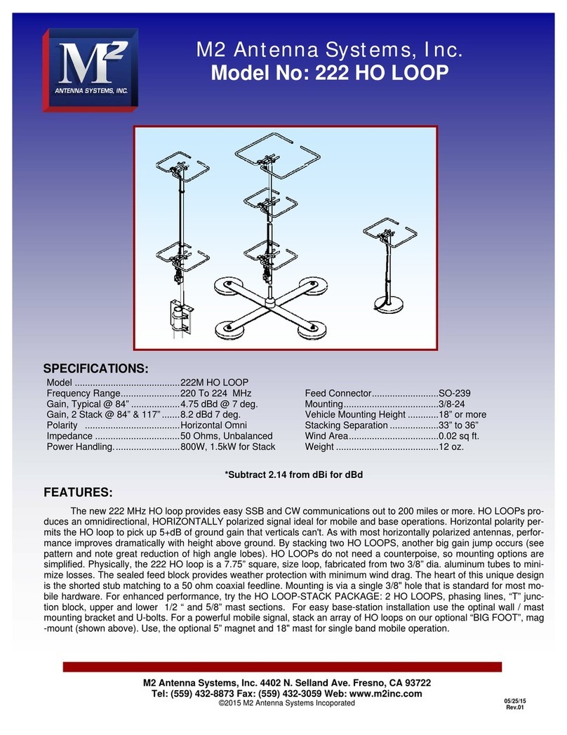
M2 Antenna Systems 222 HO LOOP User manual

M2 Antenna Systems

M2 Antenna Systems 222 HO LOOP User manual

M2 Antenna Systems 248CP22A User manual

M2 Antenna Systems

M2 Antenna Systems 248CP22A User manual

M2 Antenna Systems FGHM64 User manual

M2 Antenna Systems

M2 Antenna Systems FGHM64 User manual

M2 Antenna Systems 6M HO LOOP User manual

M2 Antenna Systems

M2 Antenna Systems 6M HO LOOP User manual

M2 Antenna Systems 40M3C User manual

M2 Antenna Systems

M2 Antenna Systems 40M3C User manual

M2 Antenna Systems 6M7JHVHD User manual

M2 Antenna Systems

M2 Antenna Systems 6M7JHVHD User manual

M2 Antenna Systems 500-1000-10 User manual

M2 Antenna Systems

M2 Antenna Systems 500-1000-10 User manual

M2 Antenna Systems 295XP6 User manual

M2 Antenna Systems

M2 Antenna Systems 295XP6 User manual

M2 Antenna Systems 403CP20 User manual

M2 Antenna Systems

M2 Antenna Systems 403CP20 User manual

M2 Antenna Systems 80M2L User manual

M2 Antenna Systems

M2 Antenna Systems 80M2L User manual

M2 Antenna Systems 222XP30 User manual

M2 Antenna Systems

M2 Antenna Systems 222XP30 User manual

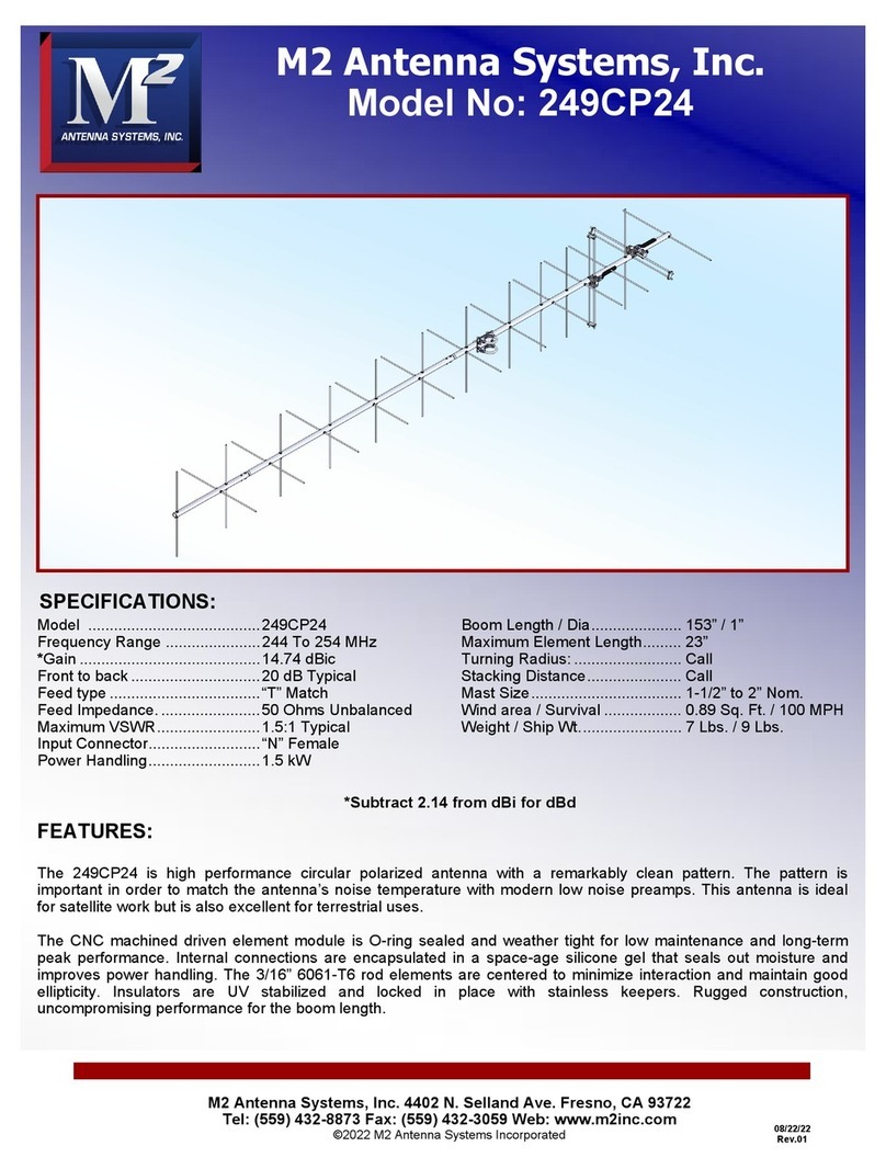
M2 Antenna Systems 249CP24 User manual

M2 Antenna Systems

M2 Antenna Systems 249CP24 User manual

M2 Antenna Systems 418CP30 User manual

M2 Antenna Systems

M2 Antenna Systems 418CP30 User manual

M2 Antenna Systems 2M-440XPSS User manual

M2 Antenna Systems

M2 Antenna Systems 2M-440XPSS User manual

M2 Antenna Systems 2M5WL User manual

M2 Antenna Systems

M2 Antenna Systems 2M5WL User manual

M2 Antenna Systems 2M7X User manual

M2 Antenna Systems

M2 Antenna Systems 2M7X User manual

M2 Antenna Systems 2068-26-2 User manual

M2 Antenna Systems

M2 Antenna Systems 2068-26-2 User manual

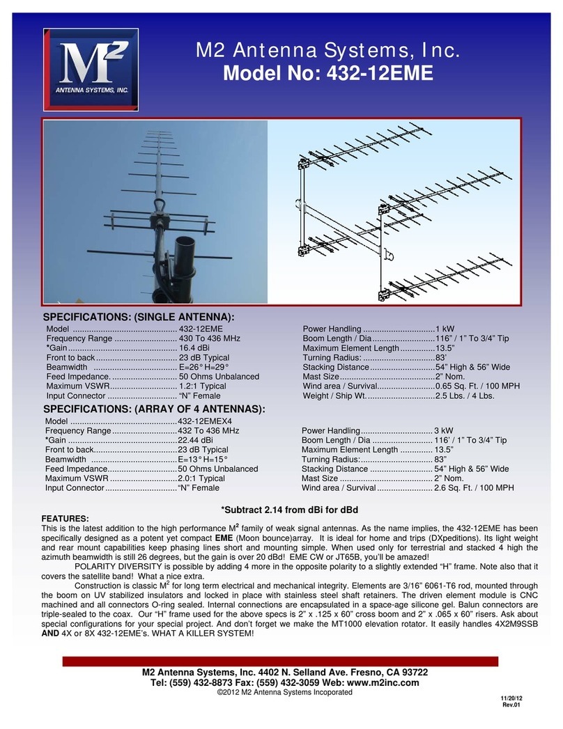
M2 Antenna Systems 432-12EME User manual

M2 Antenna Systems

M2 Antenna Systems 432-12EME User manual

M2 Antenna Systems 167XP22 User manual

M2 Antenna Systems

M2 Antenna Systems 167XP22 User manual

M2 Antenna Systems 215-470LP16 User manual

M2 Antenna Systems

M2 Antenna Systems 215-470LP16 User manual

M2 Antenna Systems 32 HO LOOP User manual

M2 Antenna Systems

M2 Antenna Systems 32 HO LOOP User manual

M2 Antenna Systems 137CP14HD User manual

M2 Antenna Systems

M2 Antenna Systems 137CP14HD User manual

M2 Antenna Systems 6M5XHP User manual

M2 Antenna Systems

M2 Antenna Systems 6M5XHP User manual

M2 Antenna Systems 17M5DX User manual

M2 Antenna Systems

M2 Antenna Systems 17M5DX User manual

Popular Antenna manuals by other brands

MicroNet SP920MA-8 Quick installation guide

MicroNet

MicroNet SP920MA-8 Quick installation guide

Shakespeare Electronic Style 390 installation instructions

Shakespeare Electronic

Shakespeare Electronic Style 390 installation instructions

ADC Digivance CXD Operation manual

ADC

ADC Digivance CXD Operation manual

Dielectric TFU instruction manual

Dielectric

Dielectric TFU instruction manual

Sea Tel ST88-21 C/Ku-Band TVRO Installation and operation manual

Sea Tel

Sea Tel ST88-21 C/Ku-Band TVRO Installation and operation manual

Parsec Srl GOLDEN RETRIEVER installation instructions

Parsec Srl

Parsec Srl GOLDEN RETRIEVER installation instructions

TechniSat SKYRIDER DOME instruction manual

TechniSat

TechniSat SKYRIDER DOME instruction manual

SteppIR 4 Element Yagi installation instructions

SteppIR

SteppIR 4 Element Yagi installation instructions

MFJ MFJ-1456 instruction manual

MFJ

MFJ MFJ-1456 instruction manual

Winegard HD7080P Specifications

Winegard

Winegard HD7080P Specifications

Applied Satellite Engineering ComCenter-II 'Outdoor' product manual

Applied Satellite Engineering

Applied Satellite Engineering ComCenter-II 'Outdoor' product manual

JVC KV-AT3003 instructions

JVC

JVC KV-AT3003 instructions

Poynting XPOL-1-5G user guide

Poynting

Poynting XPOL-1-5G user guide

Monster EDGE 60 PLUS user manual

Monster

Monster EDGE 60 PLUS user manual

Steren ANT-1550 instruction manual

Steren

Steren ANT-1550 instruction manual

Shure UA844+Z18 quick start guide

Shure

Shure UA844+Z18 quick start guide

Winegard TR-6018 instructions

Winegard

Winegard TR-6018 instructions

Emos J0687 manual

Emos

Emos J0687 manual

manuals.online logo
manuals.online logoBrands
  • About & Mission
  • Contact us
  • Privacy Policy
  • Terms and Conditions

Copyright 2025 Manuals.Online. All Rights Reserved.