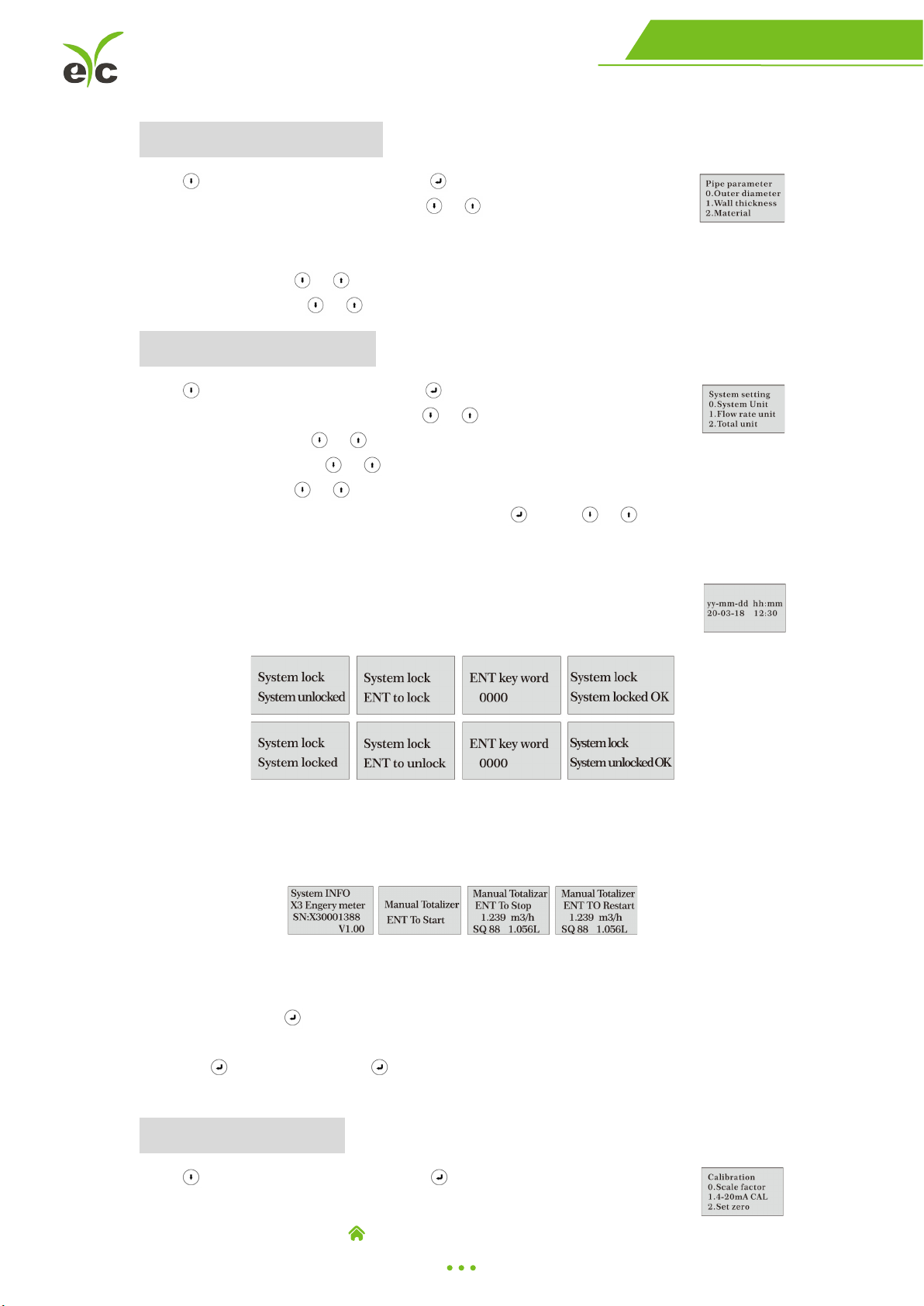
EYC FUMD User manual

Operation Manual
eYc FUMD Clamp-on Ultrasonic Flow Transmitter
eYc XXXXX
eYc FUMD

www.eyc-tech.com
1
Clamp-on Ultrasonic Flow
Flow
Contents
1. Notice-------------------------------------------------------------------------------P.02
2. Product component-------------------------------------------------------------P.0 2
3. Installation and Connection---------------------------------------------------P. 0 3
4. Panel Function--------------------------------------------------------------------P. 03
5. Powering on-----------------------------------------------------------------------P.0 4
6. Keypad Functions----------------------------------------------------------------P.0 4
7. Window descriptions----------------------------------------------------------- P.0 4
Display Menu---------------------------------------------------------------- P. 04
Setup Menu------------------------------------------------------------------ P.04
Setup Menu-Pipe parameter-------------------------------------------- P.05
Setup Menu-System setting--------------------------------------------- P. 0 5
Setup Menu-Calibration-------------------------------------------------- P. 0 5
Setup Menu-Output------------------------------------------------------- P.0 6

www.eyc-tech.com
2
Clamp-on Ultrasonic Flow
Flow
Notice
Thank you for choosing eYc FUMD Clamp-on Ultrasonic Flow Transmitter.
This operation manual contains the important using and operation information of the
flow transmitter. Please read carefully the reference manual before operation to make
your flow transmitter exert the best performance.
If you make a mistake there will be affected the transmitter's working and reduce the
transmitter's life or cause some malfunctions.
Product component
Inspection should be made before installing the flow transmitter. Check to see if the spare
parts are in accordance with the packing list. Make sure that there is no potential damage
to the enclosure due to a loose screw or loose wire, which occurred during transportation.
Any questions, please contact your representative as soon as possible.

www.eyc-tech.com
3
Clamp-on Ultrasonic Flow
Flow
Installation and Connection
Once the flow transmitter is installed, it can be connected.
You can be found the cable have 5 pin terminals, as per wiring diagram to connect
4 ... 20 mA output, RS-485.
Panel Function

www.eyc-tech.com
4
Clamp-on Ultrasonic Flow
Flow
Powering on
As soon as the flow transmitter is switched on, the self-diagnosis program
will start to run.
Signal Quality (SQ value)
Q value is short for Signal Quality. It indicates the level of the signal detected. Q value is
indicated by numbers from 0 ... 99 represent the minimum signal detected while 99
represent the maximum.
Normally, the transducer position should be adjusted repeatedly and coupling compound
should be checked frequently until the signal quality detected is as strong as possible.
Keypad Functions
Follow these guidelines when using the flow transmitter keypad:
Setting or display mode, when it is setting mode, that can return to the previous menu,
and scroll up and down to select the menu, when press move to next digit, press
and the numbers scroll from 0 ... 9, you can select the number. Press to confirm.
Window descriptions
Display Menu
■When the power on, the transmitter will display Velocity / Net
Totalize. Display data and time, velocity and net totalize.
■Press will display Flow Rate / Net Totalize.
Press will return to previous menu. Display signal quality. Time,
flow rate and velocity.
■Press will display Flow Rate / Velocity / Net Totalize.
Press will return to previous menu. Display signal quality. Time,
velocity, flow rate and net totalize.
■Press will display Run-time / Daily Totalize / Month Totalize / Year
Totalize. Press will return to previous menu. Display Run-time, Data,
Month and Year net totalize.
Setup Menu
Press will display Setup menu.
The following options are available ( by or buttons)
0. Pipe parameter
1. System setting
2. Calibration
3. Output setting

www.eyc-tech.com
5
Clamp-on Ultrasonic Flow
Flow
Setup Menu-Pipe parameter
Press , Select 0. Pipe parameter, then display:
The following options are available ( by or buttons)
0. Outer diameter
1. Wall thickness
2. Material:Move or can option PVC, Carbon steel, Steel, Copper pipe.
3. Fluid type:Move or can option Water, Sea Water, Oil ... etc.
Setup Menu-System setting
Press , Select 1. System setting, then display:
The following options are available (by or buttons)
0. System unit:Move or can option Metric, English.
1. Flow rate unit:Move or can option m3/h, LPM, GPM.
2. Total unit:Move or can option m3, L, GAL.
3. Totalize RESET:All parameters are reset, press , move or arrow to select
“YES” or “NO”. After “YES” is selected.
4. Time set
Generally, it is unnecessary to modify date time as the system is provided
with a highly reliable perpetual calendar chip.
5. System lock
Once the system is locked, any modifications to the system are prohibited, but the
parameter is readable.”Unlock” using your designated password. The password is
composed of 1 … 4 numbers.
6. System INFO
System INFO:Display serial number (SN) of the meter. This SN is the only one
assigned to each flow meter ready to leave the factory. The factory uses it for files
setup and for management by the user.
Set zero:Press ; reset “ZERO Point” which was set by the user.
Manual totalizer:The manual totalize is a separate totalize.
Press to start, and press to stop it. It is used for flow measurement and
calculation.
Setup Menu-Calibration
Press , Select 2. Calibration, and then display:

www.eyc-tech.com
6
Clamp-on Ultrasonic Flow
Flow
0. Scale factor
Refers to the ratio between “actual value”and “reading value”. For
example, when the measurement is 2.00, and it is indicated at 1.98 on the
instrument, the scale factor constant is 1.01.
1. 4 … 20 mA CAL:Check if the current loop has been calibrated
before leaving the factory. Press move to display 4 mA
or 24 mA, and at the same time, check with an ammeter to
verify that Current Loop output displayed values. It is necessary to re-calibrate the
current loop, if over the permitted tolerance.
2. Set zero Press ; reset “Zero Point” which was set by the
user.
3. Low flow cut:Flow rate falls below the low flow cutoff value.
The flow indication is driven to zero. This function can prevent the flow meter from
reading flow after a pump as shut down but there is still liquid movement in the pipe,
which will result in totalization error.
Generally, 0.03 m/s is recommended to enter as the low flow cutoff point. The low flow
cutoff value has no relation to the measurement results once the velocity increases over
the low flow cutoff value.
Setup Menu-Output
Press , Select 3. Output setting, and then display:
0. RS-485 setup
The window used to set serial port. It connection with the equipment of
its serial port set of parameters must match. The first choice of data that
baud rate:2400, 4800, 9600, 19200 choice. The second option that in check, None.
Data length fixed to eight; Stop bit for a fixed length; Factory serial port parameters
for the default “9600, 8, None, 1”.
1. 4 ... 20 mA range
Set the Current loop output value according to the flow
value at 4 mA, and 20 mA. The flow unit is m3/h.
2. Alarm value (Option)
Enter the low alarm value; any of the measured flow, which is lower
than the low value, will activate the alarm in the OCT hardware or relay
output signal. Enter the high alarm value; any of the measured flow, which is higher
than the high value, will activate the alarm in the OCT hardware or relay output
signal.

www.eyc-tech.com
7
Clamp-on Ultrasonic Flow
Flow
Tel.: 886-2-8221-2958 ,
Web : www.eyc-tech.com
e-mail : info@eyc-tech.com
Sustainable | Green | Professional
Temp. & Humid. / Dew Point / Air Velocity & Volume / Flow / Pressure
Measuring Specialist
Table of contents
Other EYC Measuring Instrument manuals